Week 9 - Parametric study on Gate valve.
Aim: Perform a simulation to analyse flow through a gate valve.
Also perform a parametric study to analyse the flow rate at the outlet of the gate valve through various level of lift of the gate disc.
Theory about the Gate valves:
A gate valve, also known as a sluice valve, is a valve that opens by lifting a barrier (gate) out of the path of the fluid. Gate valves require very little space along the pipe axis and hardly restrict the flow of fluid when the gate is fully opened. The gate faces can be parallel but are most commonly wedge-shaped (in order to be able to apply pressure on the sealing surface).
Typical uses:
Gate valves are used to shut off the flow of liquids rather than for flow regulation. When fully open, the typical gate valve has no obstruction in the flow path, resulting in very low flow resistance. The size of the open flow path generally varies in a nonlinear manner as the gate is moved. This means that the flow rate does not change evenly with stem travel. Depending on the construction, a partially open gate can vibrate from the fluid flow.
Gate valves are mostly used with larger pipe diameters (from 2" to the largest pipelines) since they are less complex to construct than other types of valves in large sizes.
At high pressures, friction can become a problem. As the gate is pushed against its guiding rail by the pressure of the medium, it becomes harder to operate the valve. Large gate valves are sometimes fitted with a bypass controlled by a smaller valve to be able to reduce the pressure before operating the gate valve itself.
Gate valves without an extra sealing ring on the gate or the seat are used in applications where minor leaking of the valve is not an issue, such as heating circuits or sewer pipes.
Mathematical calculations for a gate valve:
Flow Coefficient:
The flow coefficient of a device is a relative measure of its efficiency at allowing fluid flow. It describes the relationship between the pressure drop across an orifice valve or other assembly and the corresponding flow rate. Mathematically the flow coefficient Cv (or flow-capacity rating of the valve) can be expressed as:
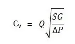
Cv is numerically equal to the number of U.S. gallons of water at 60°F that will flow through the valve in one minute when the pressure differential across the valve is one pound per square inch.
Flow Factor:
The metric equivalent flow factor (Kv) is calculated using metric units:
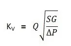
Kv can be calculated from Cv using the equation as given below:
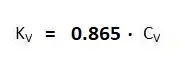
The Kv factor of a valve indicates "The water flow in m3/h, at a pressure drop across the valve of 1 kgf /cm2 when the valve is completely open.
Methodology:
Activate parameters
Adapt fluid volume to changing solid geometry.
Geometry setup:
Give Gate disc a rise of 10mm.
Sketch>Move>Hide bootom part> select component>along z-direction enter 10 mm and click ok.
Fluid volume:
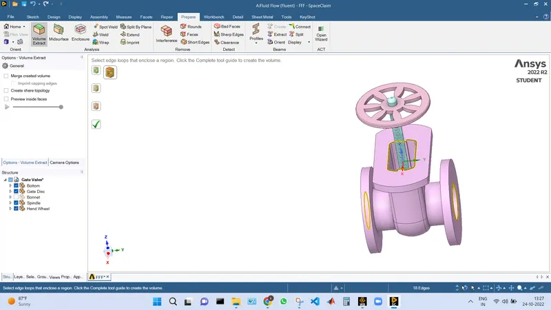
Extract the fluid volume by goin to Prepare>volume extract> select the edges>ok
Extend the fluid flow region at the Inlet and the outlet:
Pull>select face>drag >ente 800mm >ok.
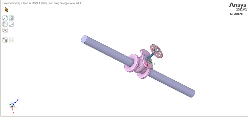
Now hide the remaining components and suppress them for physics.
Meshing:
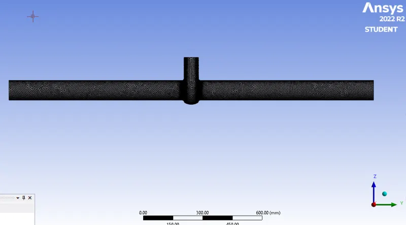
Create name selections inlet and outlet and generate the base mesh.
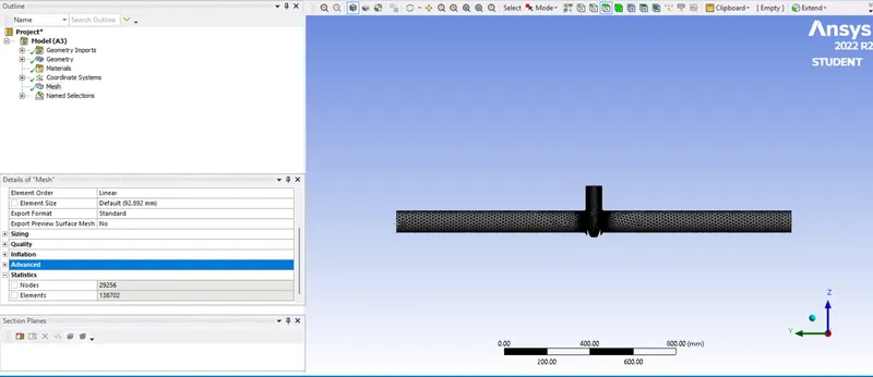
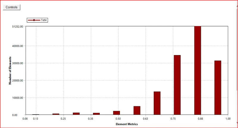
Mesh Metrics:
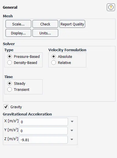
Fluent solver settings:
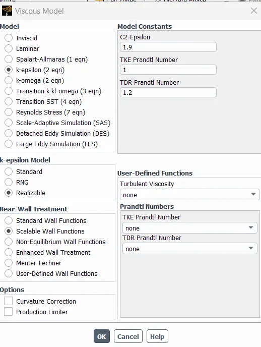
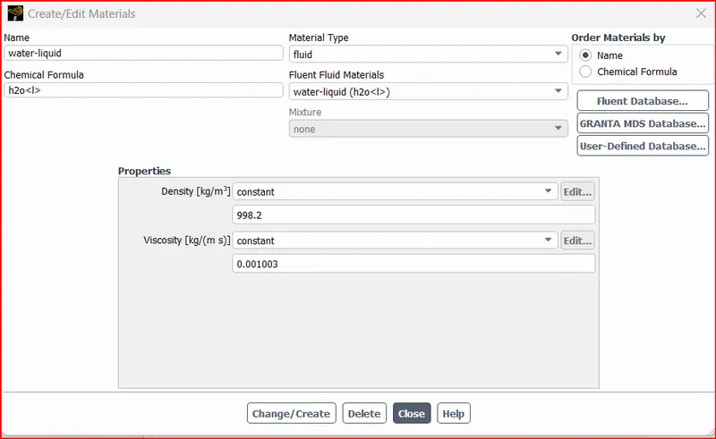
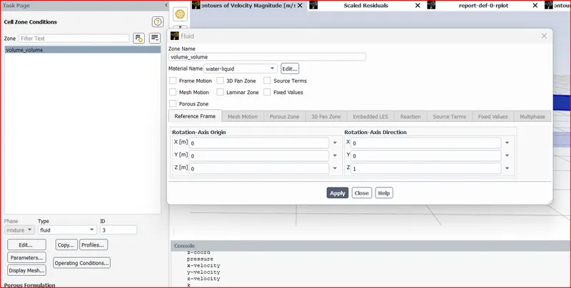
Cell zones:
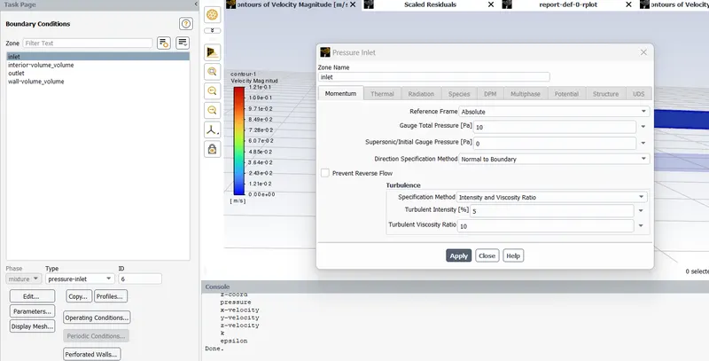
Boundaries
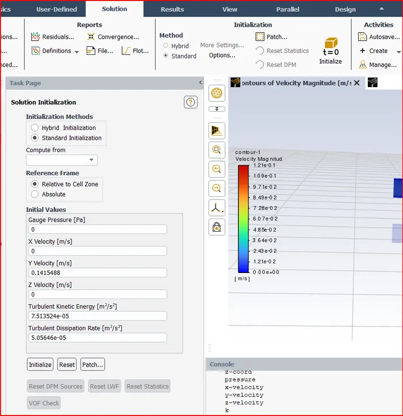
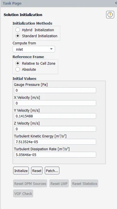
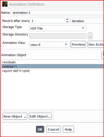
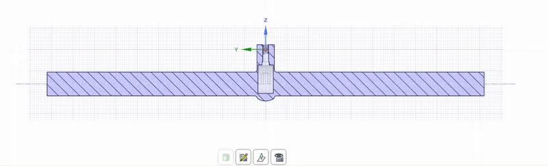
Case-1:Gate lifted by 10 mm.
Geometry
Mesh
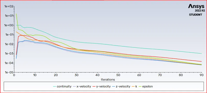
Simulation Results:
Scaled residuals:
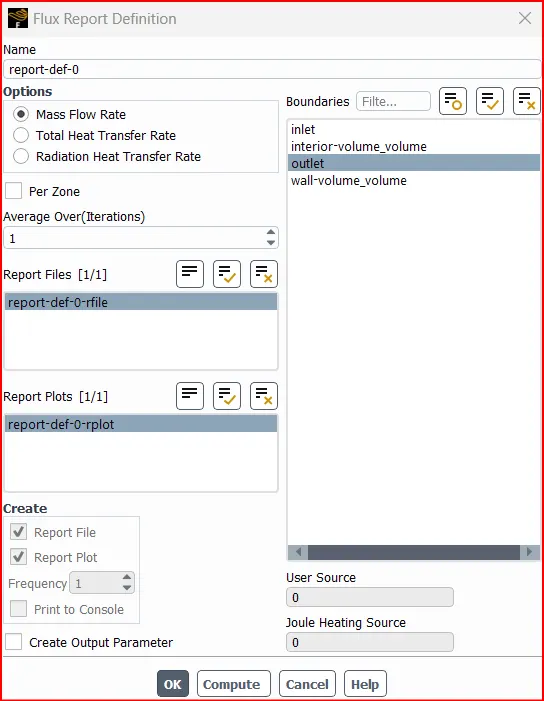
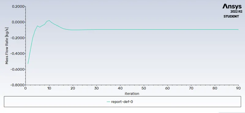
Mass flow rate through the outlet:
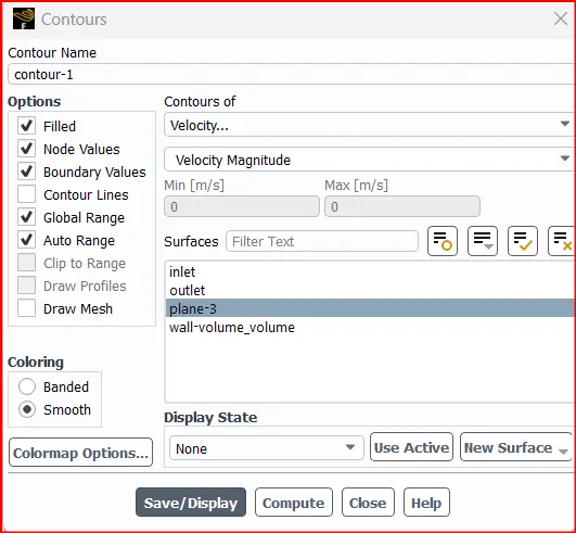
Velocity contour:
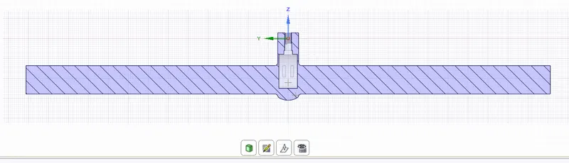
Case 2: Gate lifted by 20 mm.
Geometry setup:
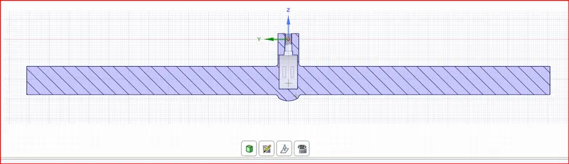
Case 3: Gate lifted by 30 mm.
Geometry setup:
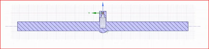
Case 4: Gate lifted by 40 mm.
Geometry setup:
Case 5: Gate lifted by 50 mm.
Geometry setup:
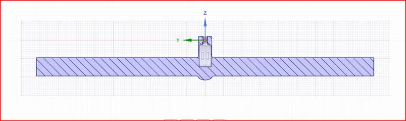
Case 6: Gate lifted by 60 mm.
Geometry setup:
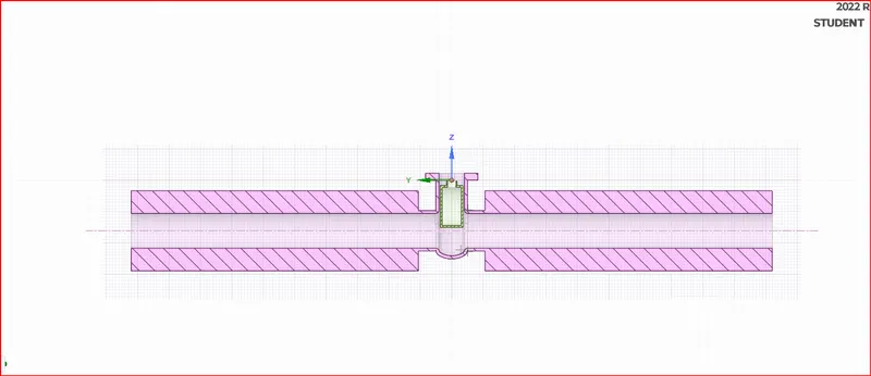
Meshing
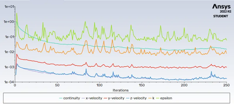
Scaled Residuals
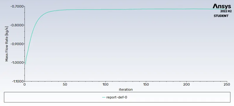
Mass flow rate:
Velocity contour
Case 7: Gate lifted by 70 mm.
Geometry setup:
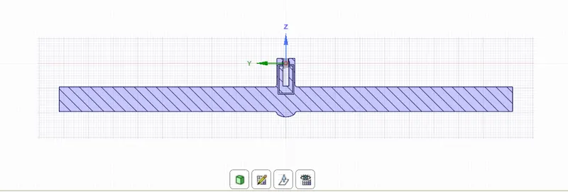
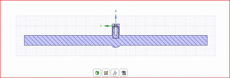
Case 8: Gate lifted by 80 mm.
Geometry setup:
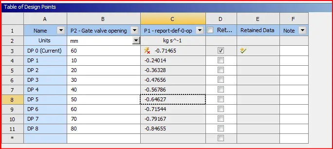
Obtain the mass flow rates at the outlet for each design point.
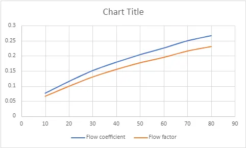
Calculate the flow coefficient and flow factor for each opening and plot the graph.
| S.No | Lift of Gate valve | Mass flow rate | Flow coefficient | Flow factor |
| 1 | 10 | 0.24 | 0.076 | 0.066 |
| 2 | 20 | 0.36 | 0.115 | 0.099 |
| 3 | 30 | 0.48 | 0.151 | 0.130 |
| 4 | 40 | 0.57 | 0.179 | 0.155 |
| 5 | 50 | 0.65 | 0.204 | 0.177 |
| 6 | 60 | 0.72 | 0.226 | 0.195 |
| 7 | 70 | 0.79 | 0.250 | 0.216 |
| 8 | 80 | 0.85 | 0.267 | 0.231 |
Graphs:
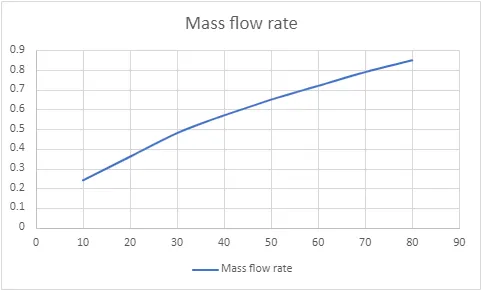
Lift of gate valve vs Mass flow rate
Conclusions
The Gate disc is moved in the steps of 10 mm and the corresponding mass flow rates are calculated.
The mass flow rate through the gate valve is computed and is observed to increase as the gate is opened.
The Flow coefficient values and flow factor are calculated for each case and is tabulated.