Week 9 - Parametric study on Gate valve.
Parametric study on Gate valve.
Aim: To perform a parametric study on the gate valve simulation.
Objectives:
The aim of this project is to carry out a parametric study on the gate valve by setting the opening from 10% to 80% with the objective to:
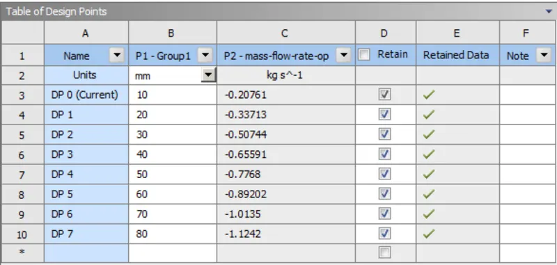
Obtain the mass flow rates at the outlet for each design point
Calculate the flow coefficient and flow factor for each opening and plot the graph
Discuss the results of the mass flow rate and flow coefficient
Introduction
A gate valve also known as a sluice valve, is a valve that opens by lifting a barrier (gate) out of the path of the fluid. Gate valves require very little space along the pipe axis and hardly restrict the flow of fluid when the gate is fully opened. The gate faces can be parallel but are most commonly wedge-shaped (in order to be able to apply pressure on the sealing surface). The work in this project is to perform a parametric study on the above device through a simulation in ANSYS Fluent. This is done by creating a parameter in Space Claim with an opening of 10 mm and further, the data for other opening values corresponding to other design points is obtained by updating the parameter.
Theory
As defined above, gate valves are devices that are used to shut off the flow of liquids rather than for flow regulation. When fully open, the typical gate valve has no obstruction in the flow path, resulting in very low flow resistance. The size of the open flow path generally varies in a nonlinear manner as the gate is moved. This means that the rate does not change evenly with stem travel. Gate valves are mostly used with larger pipe diameter since they are less complex to construct than other types of valves in large sizes. At high pressures, friction can become a problem. As the gate is pushed against its guiding rail by the pressure of the medium, it becomes harder to operate the valve. Large gate valves are sometimes fitted with a bypass controlled by a smaller valve to be able to reduce the pressure before operating valve itself. Gate valves without an extra sealing ring on the gate or the seat are used in applications where minor leaking of the valve is not an issue, such as heating circuits or sewers.
As far as the gate valve structure is concerned, it is actuated by a threaded stem that connects the actuator (handwheel) to the gate. It is characterized as having either a rising or a non-rising stem, depending on which end of the stem is threaded. Rising stems are fixed to the gate and rise and lower together as the valve is operated, providing a visual indication of valve position. The actuator is attached to a nut that is rotated around the threaded stem to move it. Non rising stem valves are fixed to and rotate with the actuator and are threaded into the gate. Gate valves are typically constructed from cast iron, cast carbon steel, ductile iron, gunmetal, stainless steel, alloy steel and forged steel. The different components of gate valve are: Bonnet, Pressure seal bonnet, knife gate, the handwheel, the gate disc, the bottom, etc.
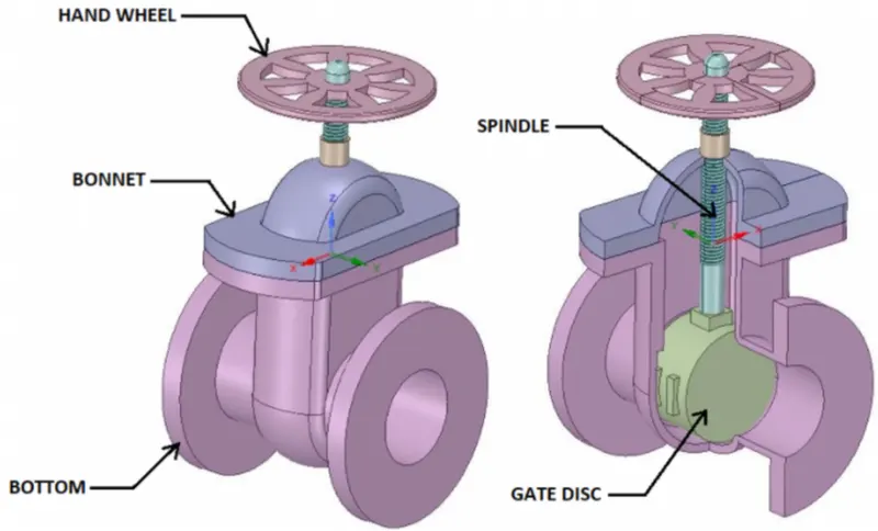
Parametric Study:
One of the best ways to get value out of your simulation is to do a parametric analysis. With very little marginal work a completed model can be parameterized to simulate scenarios limited only by your computational time and resources. As you move forward in your design, you can assess the impact that changing certain parameters can have on the design. The parameters can include dimensional parameters. Parametric studies allow you to nominate parameters for evaluation, define the parameter range, specify the design constraints, and analyze the results of each parameter variation.
A parametric study requires the following:
- Design Objective is set to Parametric Dimensions
- Parameters nominated for use in the simulation
- Parameter ranges identified
- Design criteria specified
- Various configurations generated
When you have the configurations generated you can then evaluate your simulation. You can further refine the parameters or design constraints until satisfied with the results. Once you determine that a configuration satisfies your design needs, you are able to promote that configuration back to the model as a CAD edit. You are prompted whether to make changes.
Flow Coefficient:
The flow coefficient of a device is a relative measure of its efficiency at allowing fluid flow. It describes the relationship between the pressure drop across an orifice valve or other assembly and the corresponding flow rate. Mathematically the flow coefficient Cv (or flow-capacity rating of the valve) can be expressed as:
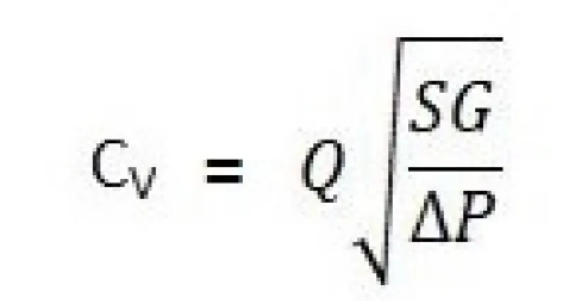
In more practical terms, the flow coefficient Cv is the volume (in US gallons) of water at 60 °F that will flow per minute through a valve with a pressure drop of 1 psi across the valve. The use of the flow coefficient offers a standard method of comparing valve capacities and sizing valves for specific applications that are widely accepted by the industry. The general definition of the flow coefficient can be expanded into equations modeling the flow of liquids, gases, and steam using the discharge coefficient.
The Kv factor of a valve indicates "The water flow in m3/h, at a pressure drop across the valve of 1 kgf /cm2 when the valve is completely open.
SIMULATION
GEOMETRY:
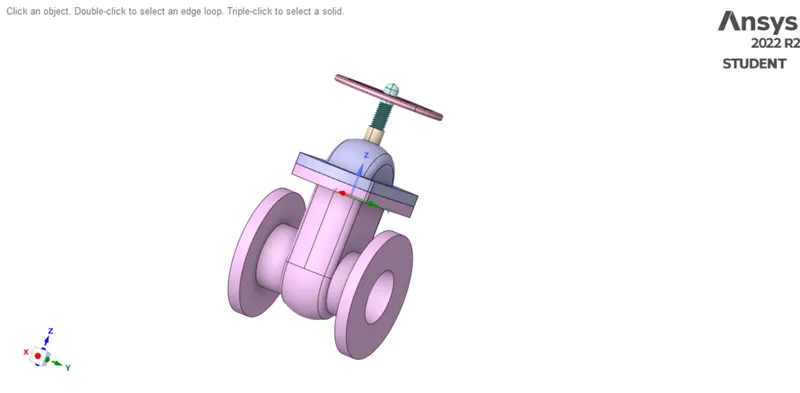
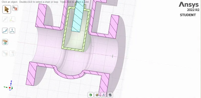
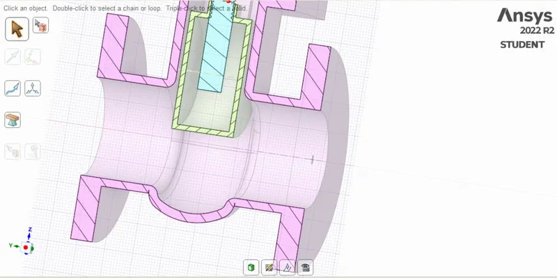
Geometry is imported into Space Claim.
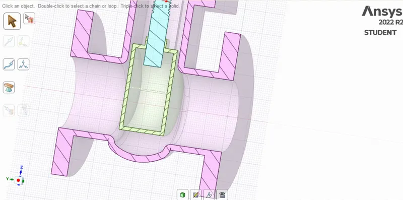
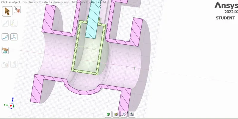
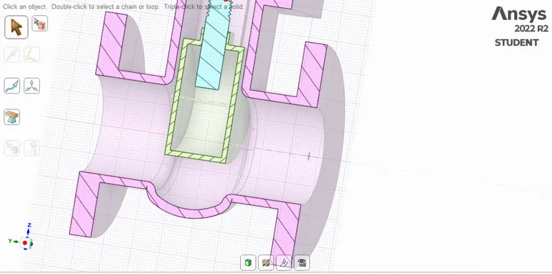
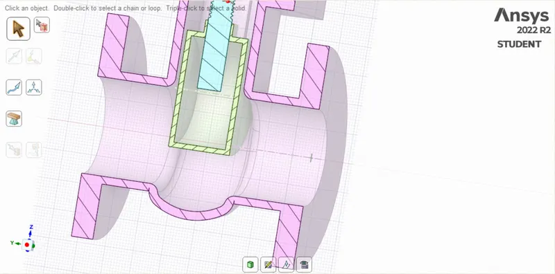
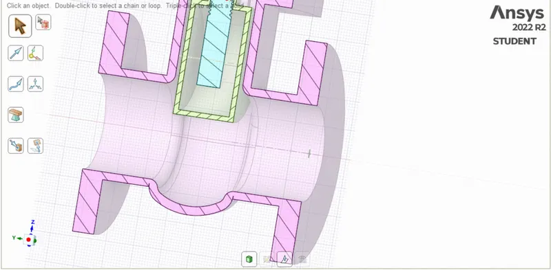
Then the gate disc component is selected and given a lift of 10mm by using the move tool available in the Ansys Space Claim and the lift is parameterized.
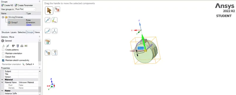
sectional view
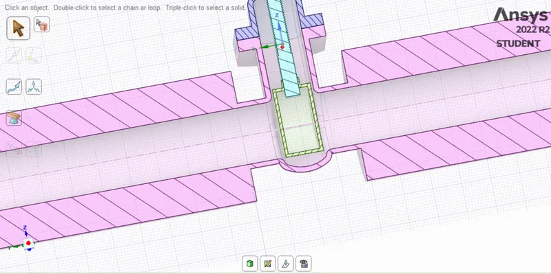
Then the inlet and outlet faces are pulled up to a distance of 800mm.
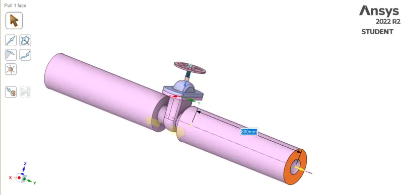
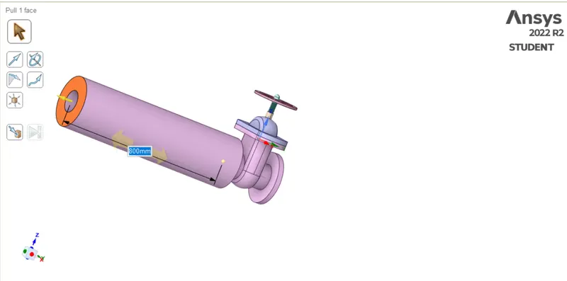
Then the fluid volume is extracted from the model by using the volume extraction tool available in Ansys Space claim.
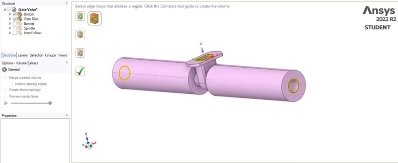
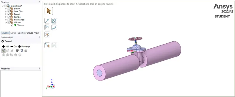
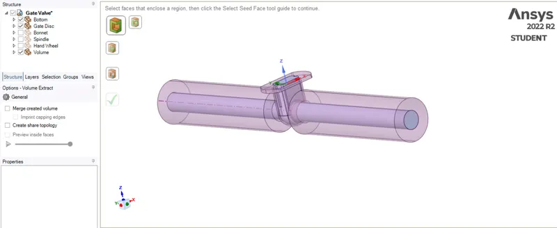
Then the solid components are suppressed for physics.
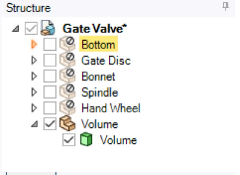
MESHING:
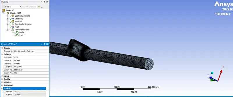
The inlet and outlet created for the left and right faces of the model as shown below.
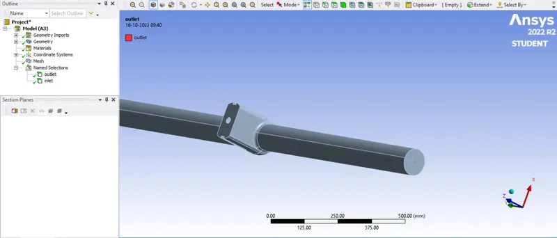
The mesh size of 60mm is applied to the model.
SOLUTION SETUP
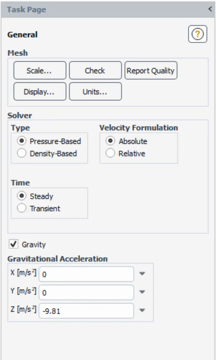
Here we are using steady state and pressure-based solver gravity of -9.81 m/s2 in z direction
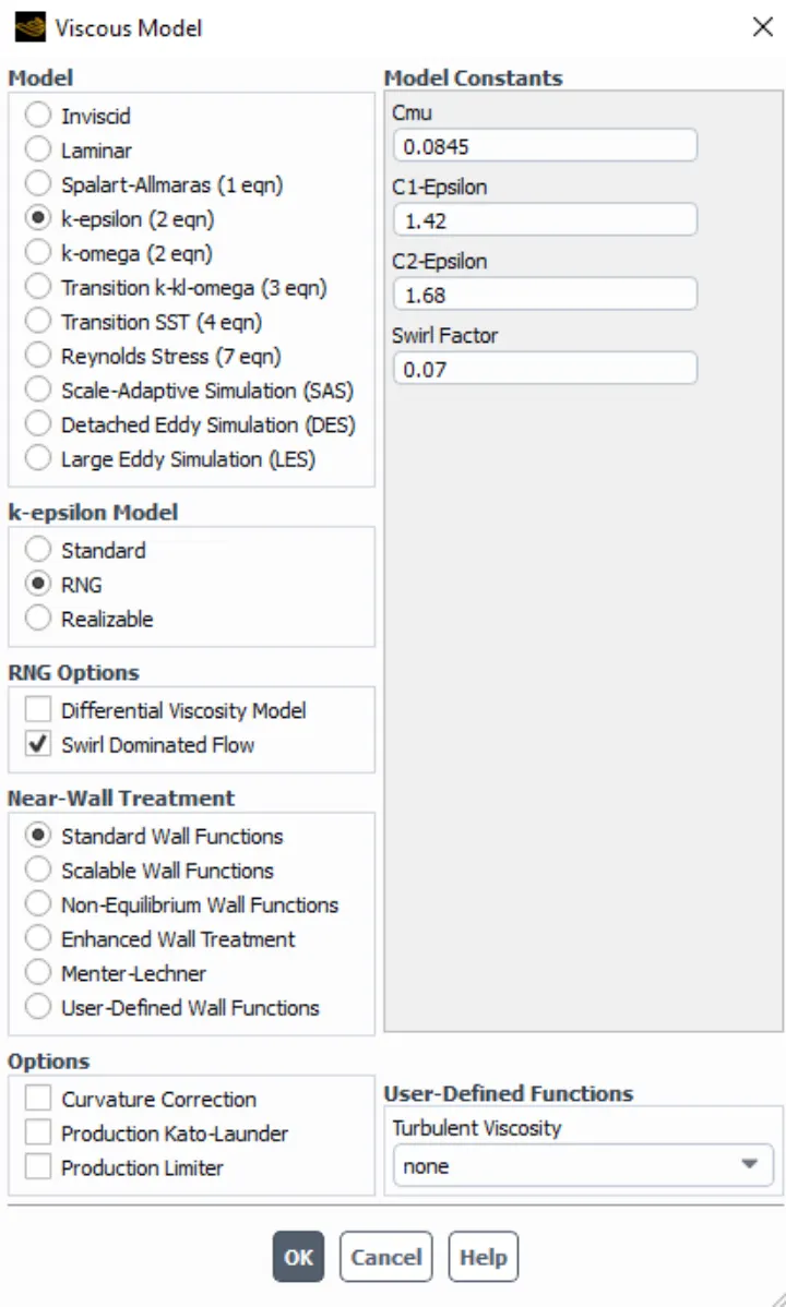
Viscous – RNG k-epsilon with swirl function given
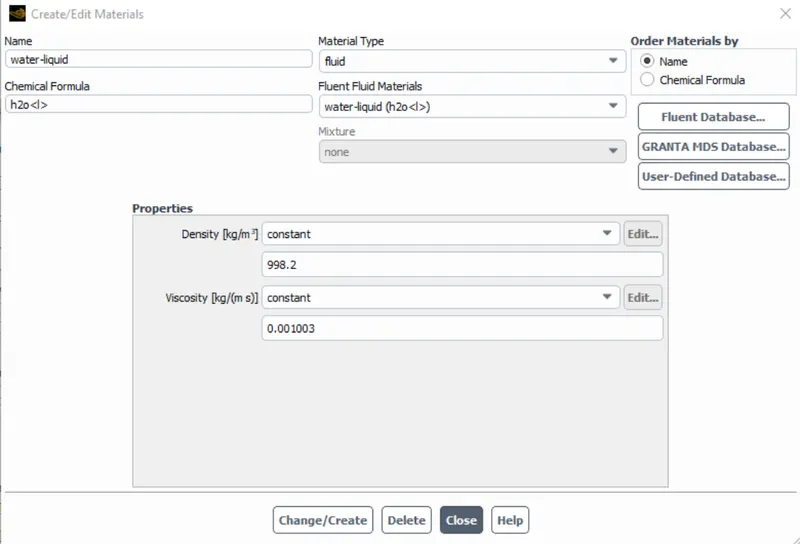
Material is given as water
CELL ZONES AND BOUNDARY CONDITIONS
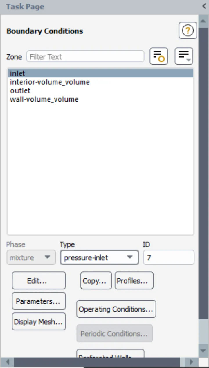
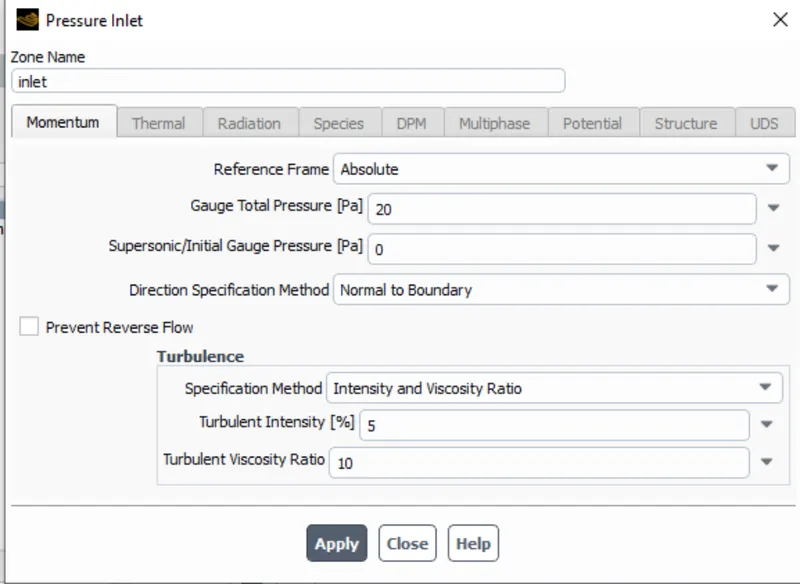
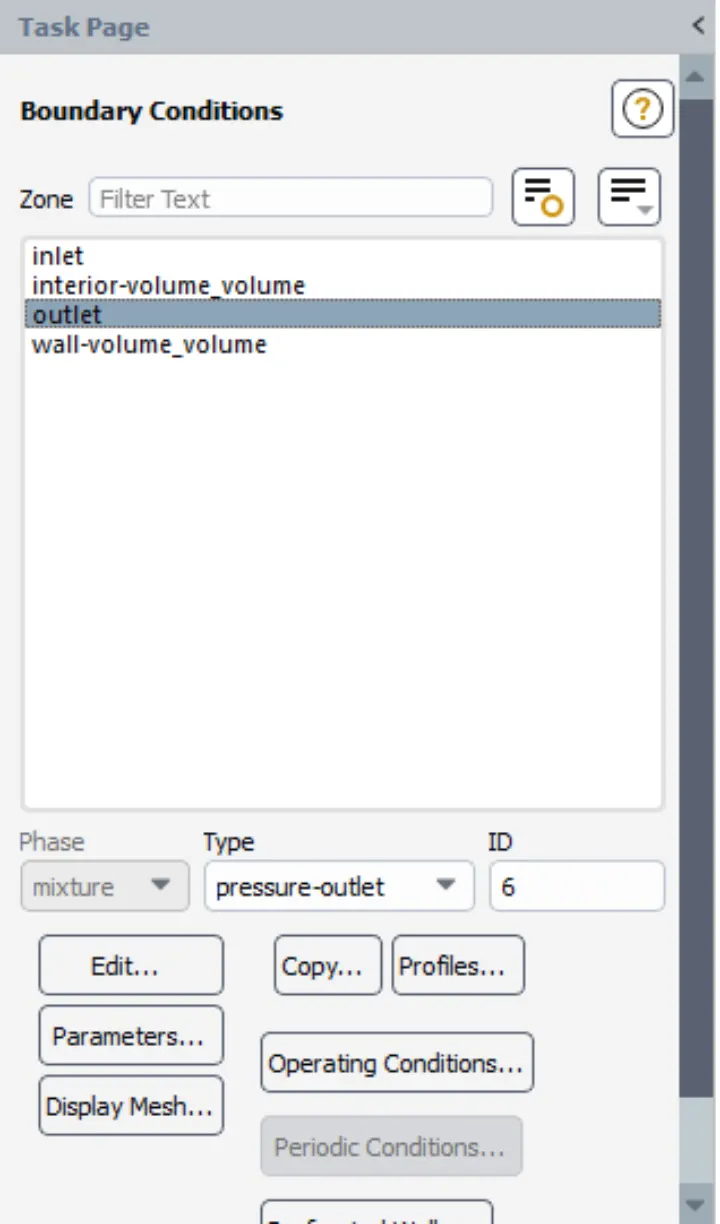
Here we are computing Mass flow rate for gate valve
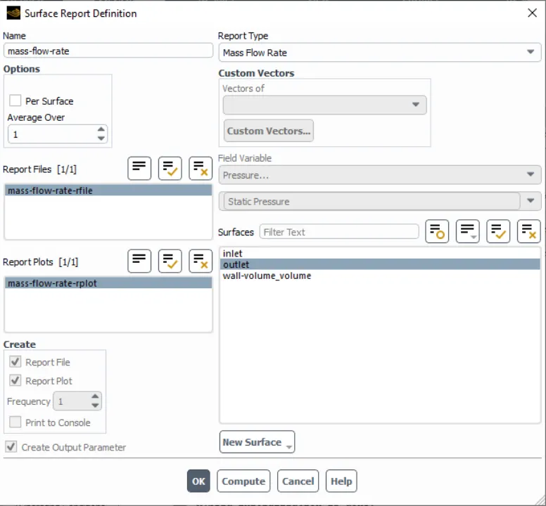
Here hybrid initialization is given and the simulation runs for 300 iterations
RESULTS
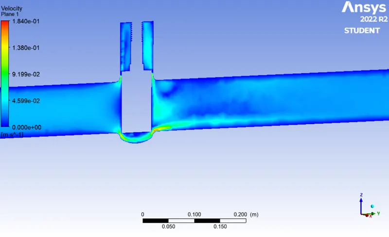
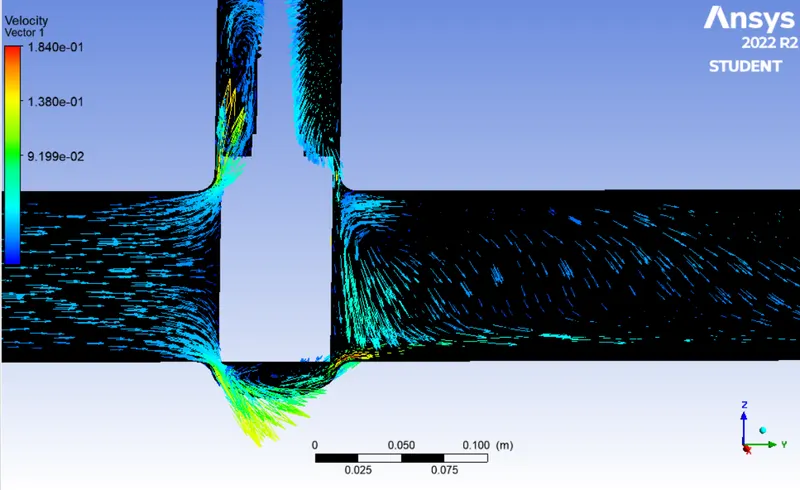
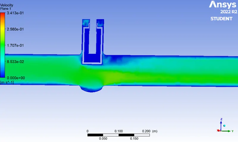
CASE 1: 10MM
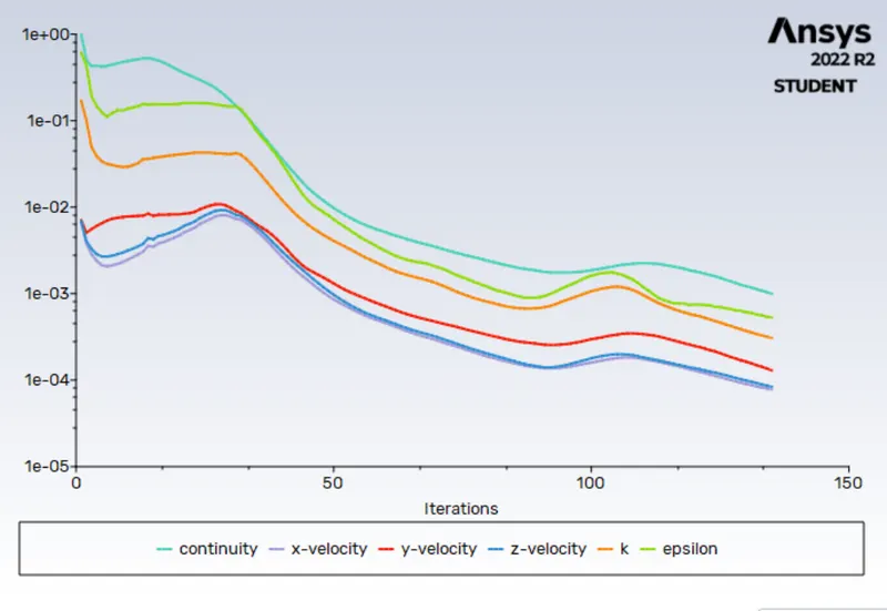
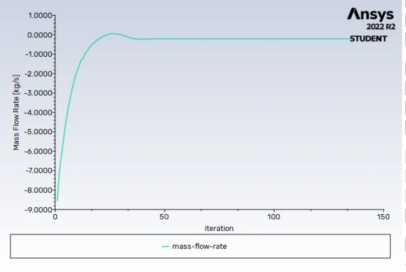
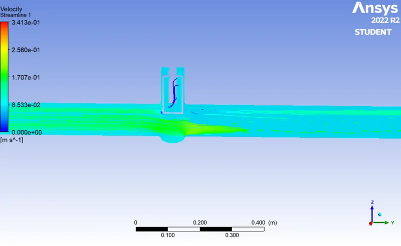
VELOCITY CONTOUR
CASE 2: 20MM
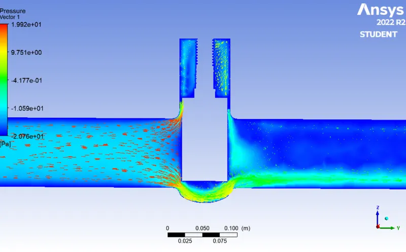
PRESSURE CONTOUR
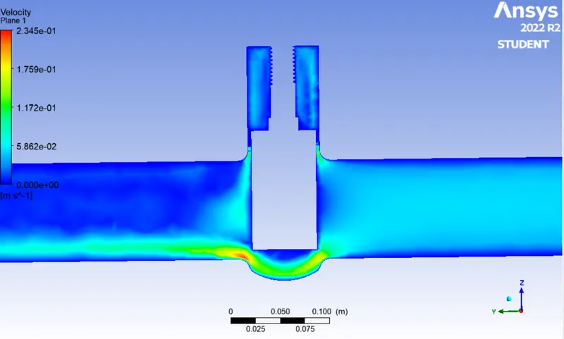
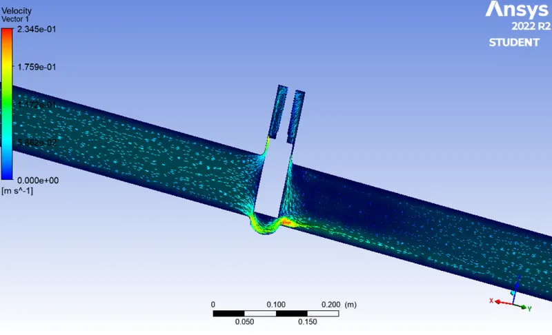
VELOCITY CONTOUR
CASE 3: 30MM
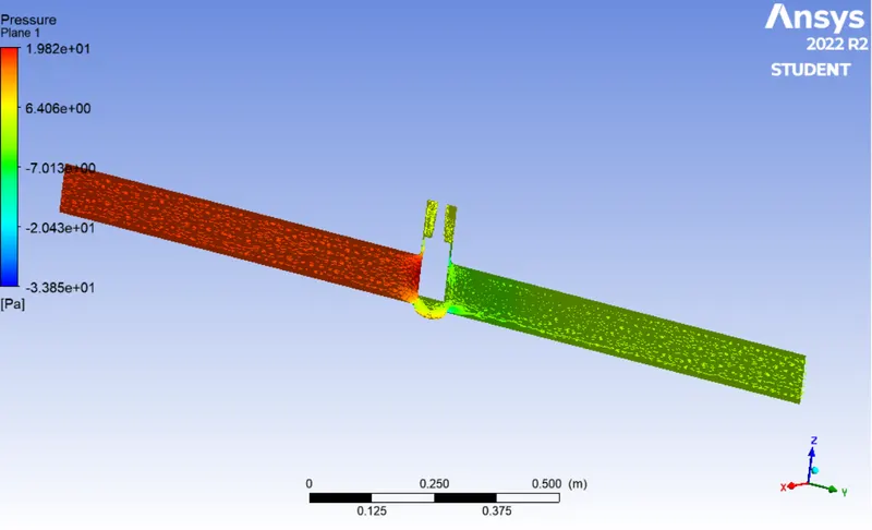
PRESSURE CONTOUR
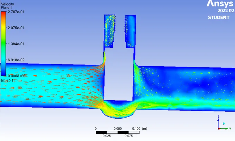
VELOCITY CONTOUR
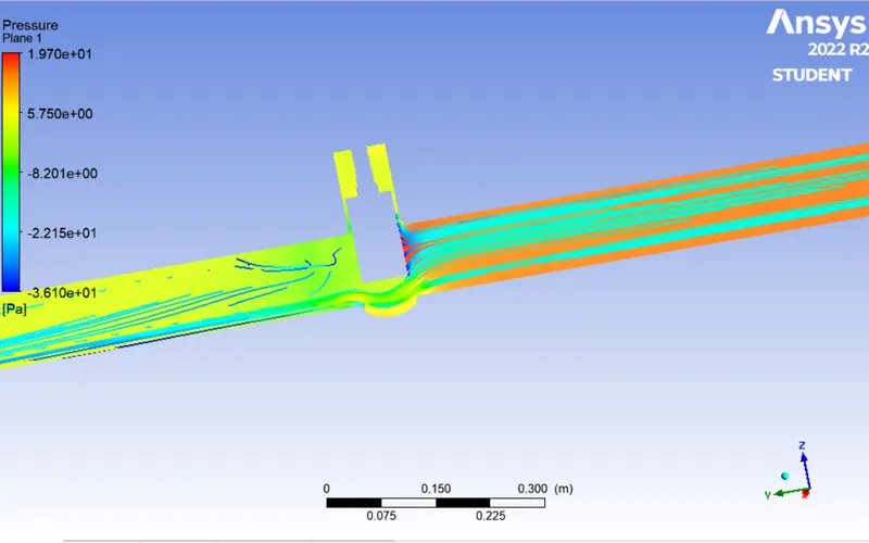
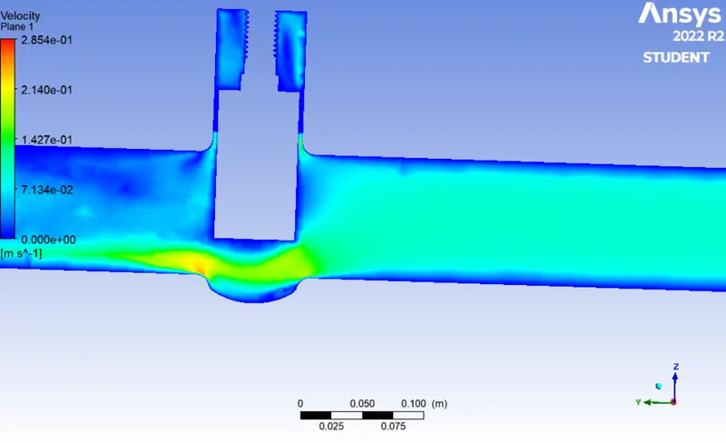
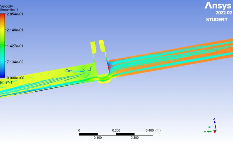
CASE 4: 40MM
PRESSURE CONTOUR
VELOCITY CONTOUR
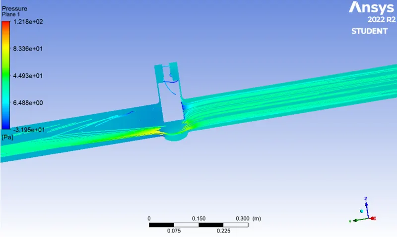
CASE 5: 50MM
PRESSURE CONTOUR
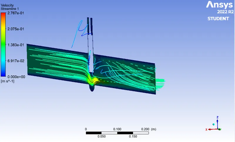
VELOCITY CONTOUR
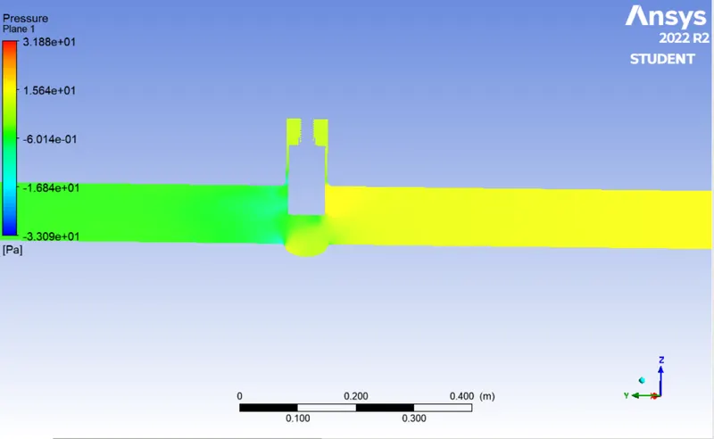
CASE 6: 60MM
PRESSURE CONTOUR
VELOCITY CONTOUR
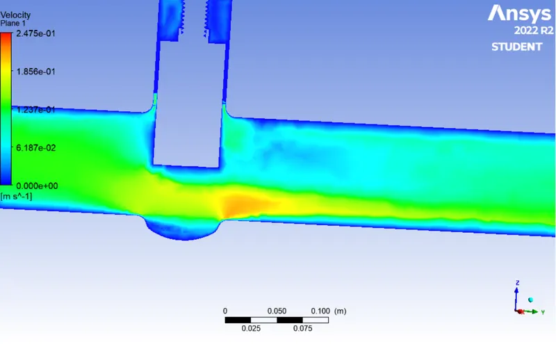
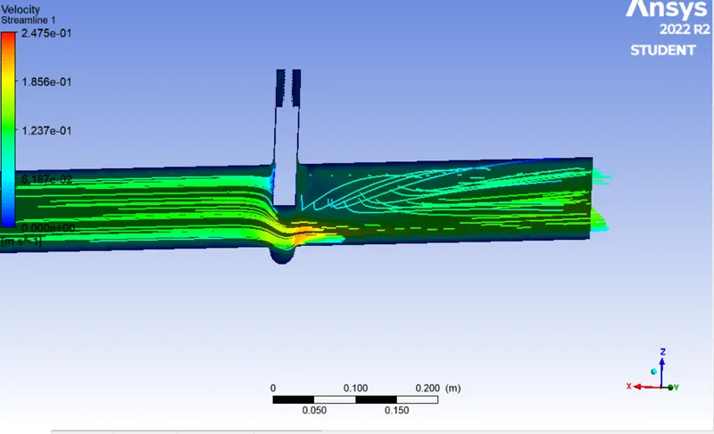
CASE 7: 70MM
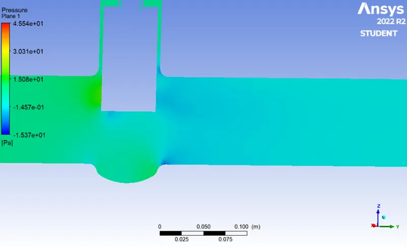
PRESSURE CONTOUR
VELOCITY CONTOUR
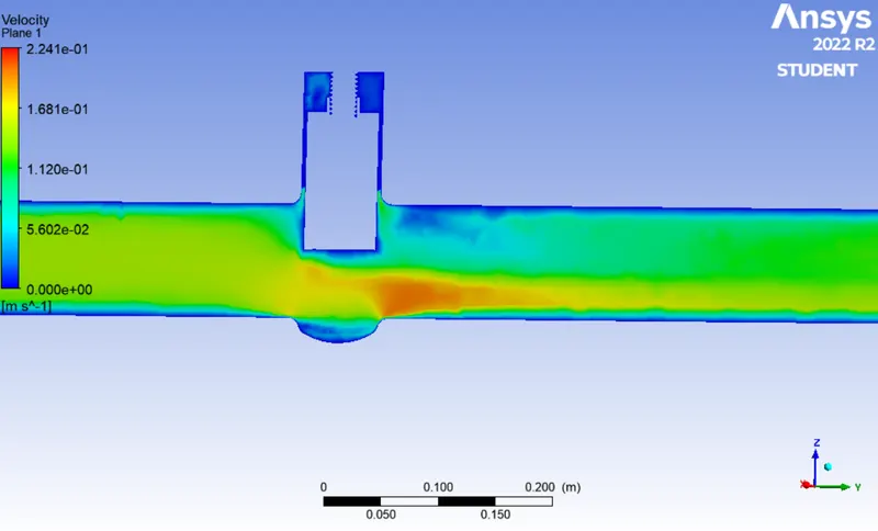
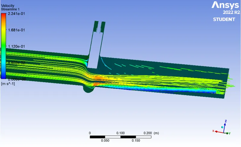
CASE 8: 80MM
PRESSURE CONTOUR
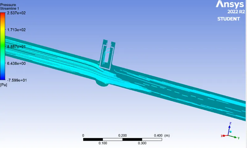
VELOCITY CONTOUR
CONCLUSION
- The negative value of mass flow rate simply indicates that mass is flowing out of our domain which gets more negative with gate rise as expected.
- From the pressure contours, it can be seen that pressure everywhere is much above the vapor pressure of water. This is desirable as below vapor pressure cavitation takes place which shortens valve life and can even damage pipeline downstream.
- From the graph, it can be seen that mass flow increases rather slowly than flow factor & flow coefficient which show their exponential nature.
- Hence a much larger flow coefficient & flow factor each time there is an increment in mass flow rate.
- As the disc lift height increases, the value of the flow coefficient and flow factor increases.
- The value of pressure below the discs decreases as the resistance to flow decreases.
- A higher value of the Flow coefficient indicates lower resistance to the flow and a lower Flow coefficient indicates higher resistance to flow.
- Flow coefficient and pressure drop are essential parameters for designing the valve and could be a great justification for the material selection of the valve.
- The mass flow rate of water increases with an increase in disc lift height, as more water can flow through the gap and there is less resistance.