Week 9 - Parametric study on Gate valve.
CHALLENGE FOR GATE VALVE SIMULATION:
For this challenge, you will have to perform a parametric study on the gate valve simulation by setting the opening from 10 % to 80%.
- Obtain the mass flow rates at the outlet for each design point.
- Calculate the flow coefficient and flow factor for each opening and plot the graph.
- Discuss the results of the mass flow rate and flow coefficient.
Submit a well-defined report with all the necessary details.
SOLUTION
AIM:
To perform a Parametric study of a gate valve.
OBJECTIVE:
- To Perform the parametric study on the gate valve by simulating the gate valve opening ranging from 10 to 80 mm.
- To obtain the mass flow for each design point.
- Calculate the flow factor and flow coefficient for each design point.
INTRODUCTION:
Gate valve:
- A Gate valve is a linear-motion manual valve with a vertical rectangular or circular disc that slides across an opening to stop the flow and acts as a “gate”. Generally used for isolation purposes fully open or closed, Gate valves are not suitable for throttling service because the high-velocity flow will cause a partially open disk to vibrate and chatter and will hasten the erosion of the disc and seating surfaces.
- The open/close flow is achieved by moving the gate of the gate valve into or out of the fluid-flow stream. The flow of the fluid through the valve can be in either direction. Gate Valve is commonly used in refineries and petrochemical plants where pressure is low, and less used in upstream facilities due to high operating pressure, long on/off times (requiring many turns of the handwheel to open it or to close it), and severe environmental conditions.
- A complete port gate valve provides a full line size (equal to pipe dimensions) thus resulting in a minimum-flow pressure drop, On the other hand, A Reduced port gate valve smaller than the line size (Flow area less than the pipe) causes a slightly high-pressure drop than a full port.
Parametric Study :
-
Parametric analysis is one of the best ways to get the most out of your simulation. A completed model can be parameterized to simulate scenarios with very little additional work, with the only constraints being your computing power and time.
-
We can evaluate the effects of changing particular parameters as you proceed with your design. Dimensional parameters may be among the parameters. You can define the parameter range, specify the design constraints, and evaluate the effects of each parameter variation using parameter studies.
Modelling Approach :
GEOMETRY:
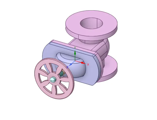
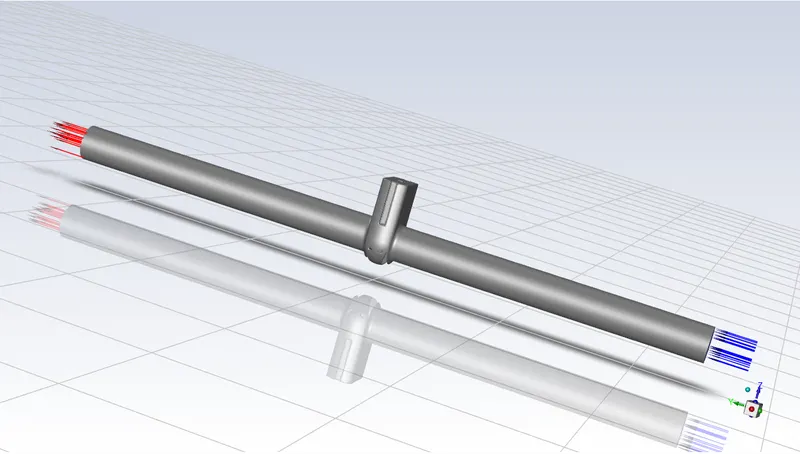
The following geometry was imported into SpaceClaim,
- Volume extraction,
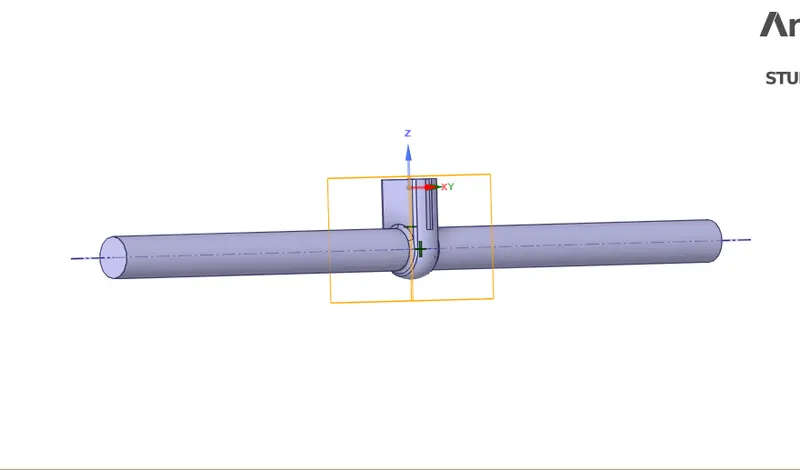
- The gate valve lift changes along with the fluid volume. The valve's vertical movement is parameterized.
-
Select the “Gate Disc” component and move in an upward direction by a “10 mm” lift. To analyze the flow and its effects, we must allow the flow, and for that, we have given the 10 mm lift to the Gate Disc.
MESHING:
- Providing the mesh size is about 5 mm.
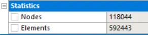
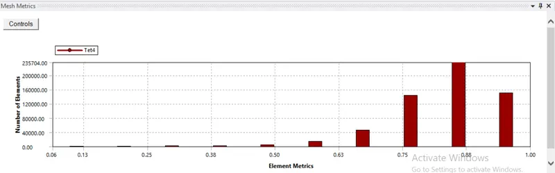
- The Element Quality is further checked and it can be noted that all the elements are of good Quality.
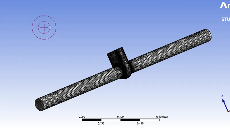
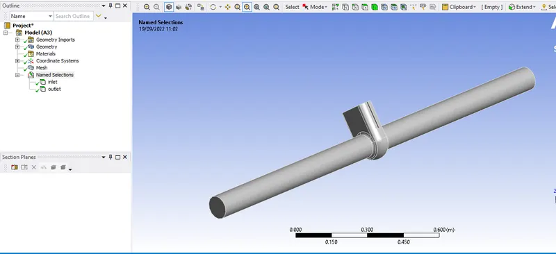
- Naming INLET and OUTLET,
SETUP:
-
Setting UP Physics:
-
The meshes are set up and the solver is defined below.
-
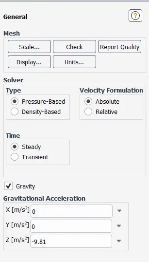
Solver type: Pressure-based solver.
-
Gravity: -9.81 negative in Z- direction
-
Solver: Steady state
-
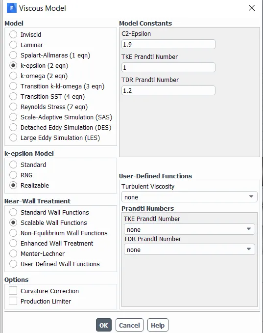
Model:k-epsilon model (realizable and scalable wall function)
-
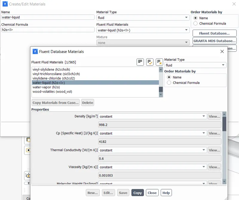
Material: water
-
Cell Zone: Fluid ( water)
-
Inlet boundary condition: Pressure inlet ( 10Pa)
-
Outlet boundary condition: Pressure outlet
-
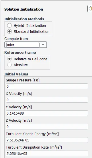
The model will be initialized with standard initialization and the data will be computed from the inlet
-
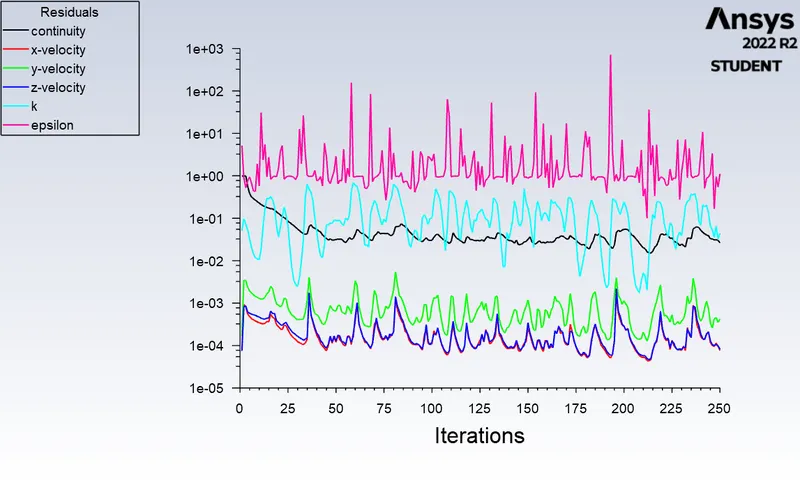
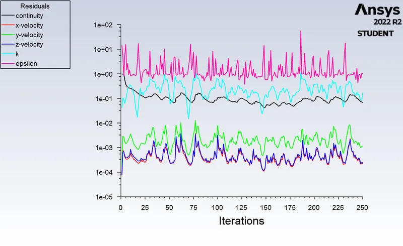
After solving for 250 no of iterations.
Results:
-
Here is the opening percentage of “Gate Disc”. According to the opening of the valve, given as lift of “Gate Disc” in mm, all 8 cases are named as given below:
- Case 1 = 10
- Case 2 = 20
- Case 4 = 40
- Case 6 = 60
- Case 8 = 80.
CASE-1:
- Gate valve lifted by 10 mm,
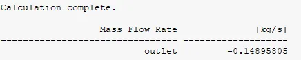
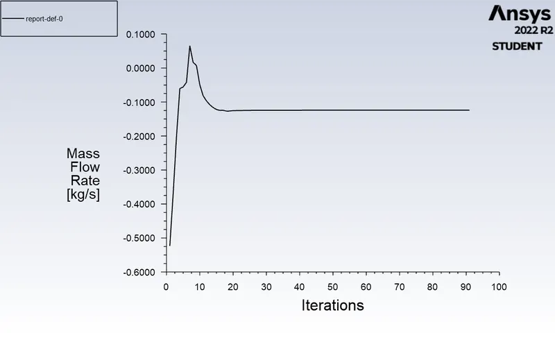
- Values of Mass flow rate at outlet:
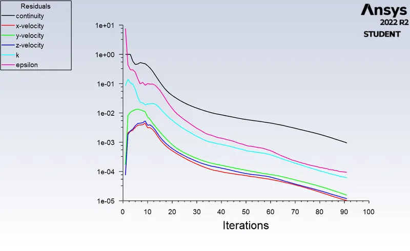
Residual
Mass Flow rate Plot:
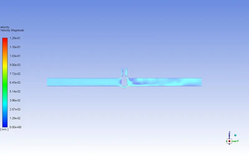
VELOCITY CONTOUR
CASE-2:
- Gate valve lifted by 20 mm,
- Values of Mass flow rate at outlet:

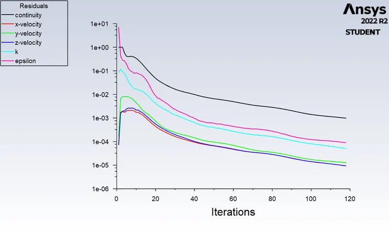
Residual
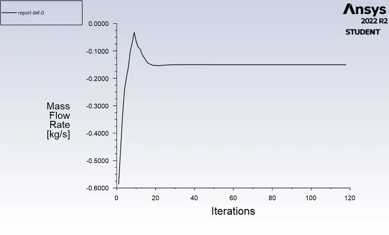
Mass Flow rate Plot:
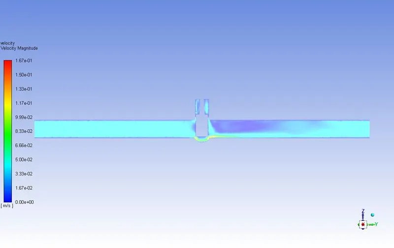
VELOCITY CONTOUR
CASE-3:
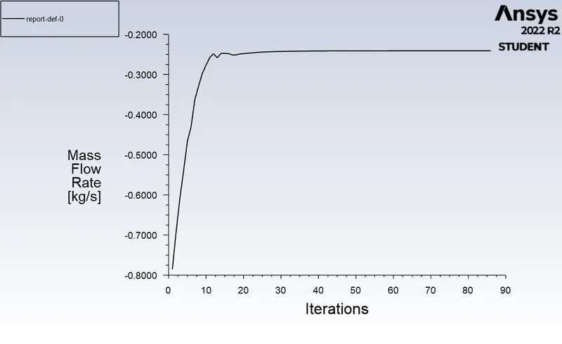
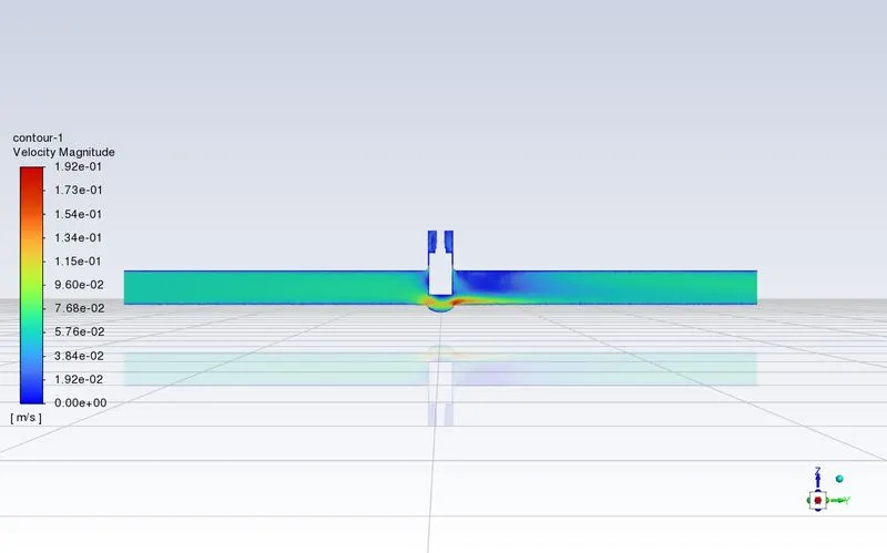
- Gate valve lifted by 40 mm,
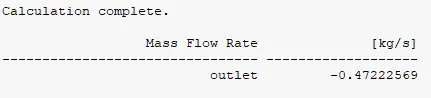
- Values of Mass flow rate at outlet:
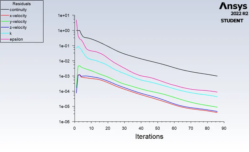
Residual
Mass Flow rate Plot:
VELOCITY CONTOUR
Flow Coefficient & Flow Factor:
Cv=Q√SG∇PCv=Q√SG∇P
Q =0.47541
SG = 1000/998.2 = 1
∇P = 10 psi
Cv=0.47541⋅√110Cv=0.47541⋅√110
Cv=0.47541⋅0.31622Cv=0.47541⋅0.31622
Cv =0.15033
Kv=0.865⋅CvKv=0.865⋅Cv
Kv=0.865⋅0.15033Kv=0.865⋅0.15033
Kv =0.13000
CASE-4:
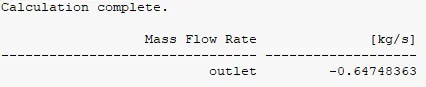
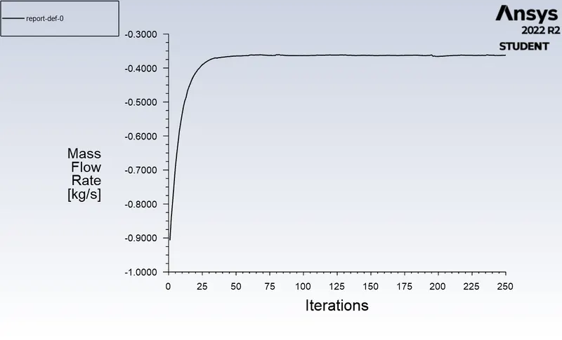
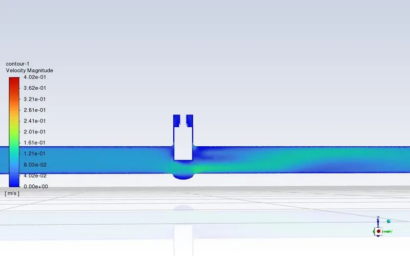
- Gate valve lifted by 60 mm,
- Values of Mass flow rate at outlet:
Residual
Mass Flow rate Plot:
VELOCITY CONTOUR
Flow Coefficient & Flow Factor:
Cv=Q√SG∇PCv=Q√SG∇P
Q =0.67343
SG = 1000/998.2 = 1
∇P = 10 psi
Cv=0.67343⋅√110Cv=0.67343⋅√110
Cv=0.67343⋅0.31622Cv=0.67343⋅0.31622
Cv =0.21295
Kv=0.865⋅CvKv=0.865⋅Cv
Kv=0.865⋅0.21295Kv=0.865⋅0.21295
Kv =0.18420
CASE-5:
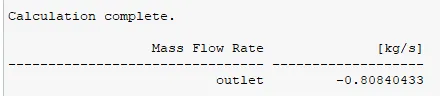
- Gate valve lifted by 80 mm,
- Values of Mass flow rate at outlet:
Residual
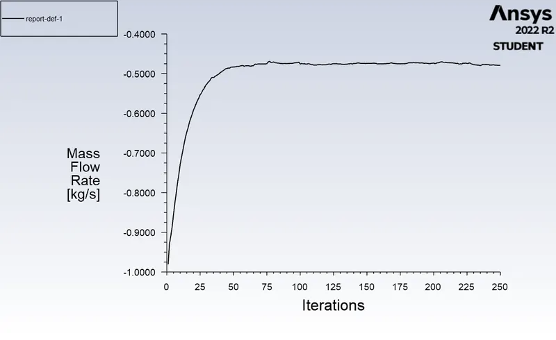
Mass Flow rate Plot:
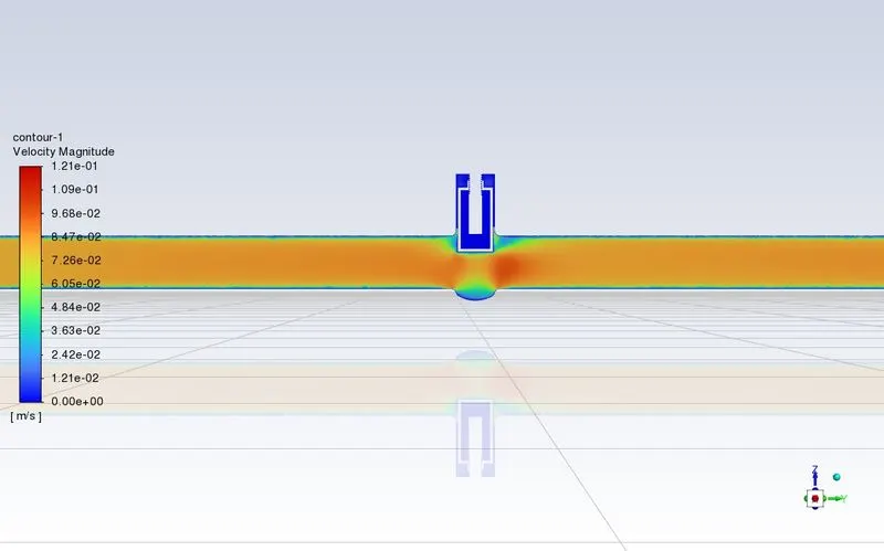
VELOCITY CONTOUR
Flow Coefficient & Flow Factor:
Cv=Q√SG∇PCv=Q√SG∇P
Q =0.62257
SG = 1000/998.2 = 1
∇P = 10 psi
Cv=0.62257⋅√110Cv=0.62257⋅√110
Cv=0.62257⋅0.31622Cv=0.62257⋅0.31622
Cv =0.19686
Kv=0.865⋅CvKv=0.865⋅Cv
Kv=0.865⋅0.19686Kv=0.865⋅0.19686
Kv =0.17029
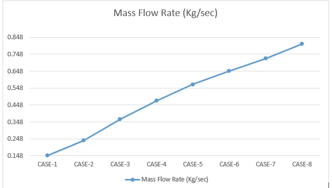
- As the opening of the Gate Valve increases, the Mass Flow Rate increases.
- Also, Increases in Flow Factor are observed at each Design Point from 10 to 80 mm Lift.
Flow Factor (Kv) :
flow rate is the flow coefficient in the metric units. It is defined as the flow rate in cubic meters per hour for water at the constant temperature of 16 degrees Celcius with a pressure drop of 1 bar across the valve.
Flow Coefficient (Cv) :
Cv is the flow coefficient in the imperial units. It is defined as the flow rate in US Gallons per minute of water at a constant temperature of 60 degrees Fahrenheit and a pressure drop of 1 psi across the valve. It is used to determine the flow under various conditions and to select the proper valve for the various applications.
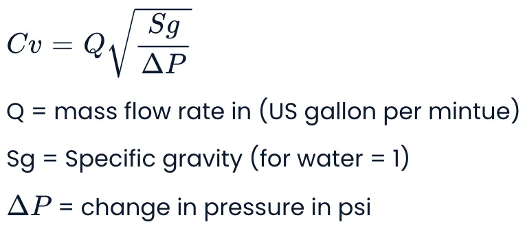
Flow factor Kv =0.865* Cv
Flow coefficient Cv= Kv/0.865
Mass flow rate graph for various cases:
CONCLUSION:
- The negative mass flow is due to the mass exiting the outlet.
- A parametric study is a time-reducing option when studying the effects of changes in certain parameters on a system.
- The variation of flow coefficient and flow factor with the opening of the valve is studied by using parametric.
- Flow coefficient plays important role in the selection of a valve and sizing of a valve, so calculating it is necessary.
- Flow coefficient also helps in computing the efficiency of the system and the effect of pressure on the system.