Week 9 - Parametric study on Gate valve.
Aim
Flow of fluid through the gate valve’s and study of parameters when valves is open in each state by applying parametric function
In this simulation the fluid water is passed through gate valves and measuring the mass flow rate , pressure , velocity at each section . mainly inlet and outlet , coefficient of flow and flow factor for valves efficiency , opening is provided from 10 mm lift to 65 mm .
Importance
It is used to measure all the parameters like mass flow rates , pressure in each section and velocity at every point in pipes . which is widely used in industries
All types of valves is used in chemical and pharmaceutical industries so it have great importance in measuring and all reading by applying the small and different size of opening , for flow , for considering mass flow rates and , required velocity , required pressure at appropriate section hence it has the great importance in measuring all point , by making simulation and getting results of it.
It is widely used in all types of valves manufacturing industries for measuring the efficiency of valves , how efficient and suitable , calculating the coefficient of flow and flow factor .
Such simulation is used in petrochemical industries.
Parametric study is suitable to give the all the result when provided suitable lift , gives all the results like mass flow rate , pressure difference , velocity variation , etc.
Solving procedure
Gate valve body is generated in space claim , after generating , both end section is extended to 800 mm from both side , then giving 10 mm lift to disc section of body and generating the volume by applying edge section selecting volume . suppressing all body of gate valve for physics and only volume is consider .
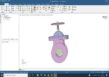
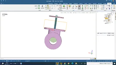
For 20mm lift after solution for 30 mm lift after result
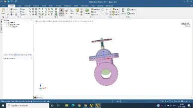
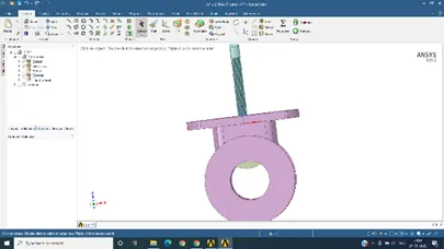
For 45 mm lift after solution for 65 mm lift after solution
In meshing section, generating meshing by selecting 5mm size and selecting the name of inlet and outlet .considering proper elements and nodes .
In fluent section , enabling gravity -9.81 in z section , enabling the viscous flow by enabling k-epsilon , realization and scalable wall function . flow is turbulence can be measure by initialling and checking in standard section, we get the velocity . then in material section we add water from fluent data base , and in cell zone we enable water instead of air by default , and again go to material section we delete air from it .after that we go to boundary condition , inlet we use pressure inlet and giving 10pa , and consider pressure outlet on it .
After initializing by considering standard initialization and starts from inlets , we generate mass flow rate report from definition , and area weighted . after that we initialize again and go to post processor
In post processor we go to plane and applying the plane at proper cut section , consider couture and plots of velocity , pressure and temperature of plane section , then again we go to the solving section , provided 600 iteration and apply run .
After considering all reports we go to space claim and activate the parametric section on disc by clicking on p , and giving proper volume consideration .
Again we check the mesh , and go to fluent section and initialize it, applying parametric p section for mass flow rale and in pressure inlet outlet section .
We go to parametric section and activate the lift for 10mm,20mm,30mm ,45mm and 65 mm, then enabling the retain data then we run the solution .
All the reports residual curve, pressure, mass flow rate and velocity couture of some section is attached.
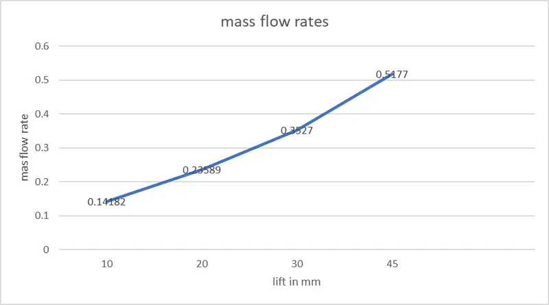
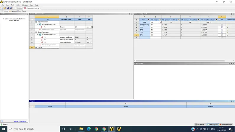
Parametric report is attached
|
sr no |
lift in mm |
mas flow rate in kg/s |
||
|
1 |
10 |
0.14182 |
||
|
2 |
20 |
0.23589 |
||
|
3 |
30 |
0.3527 |
||
|
4 |
45 |
0.5177 |
Flow coefficient / Flow factor
When flow goes through a valve or any other restricting device it loses some energy. The flow coefficient is a designing factor which relates head drop (Δh) or pressure drop (ΔP) across the valve with the flow rate (Q).
(liquids)
Q: Flow rate
ΔP: Pressure Drop
Sg: Specific gravity (1 for water)
K: Flow coefficient Kv or Cv
Kv = 0.865 x Cv
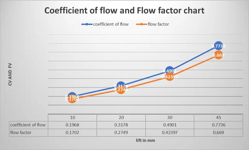
Plots of flow coefficient and flow factor is attached
|
sr no |
lift in mm |
cv |
kv |
|
1 |
10 |
0.1968 |
0.1702 |
|
2 |
20 |
0.3178 |
0.2749 |
|
3 |
30 |
0.4901 |
0.42397 |
|
4 |
45 |
0.7736 |
0.669 |
parametric report for all lift
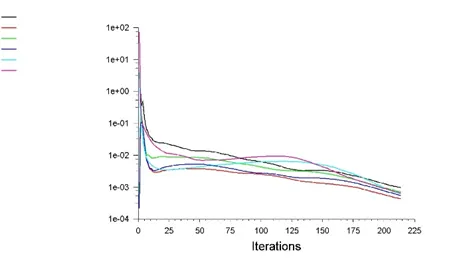
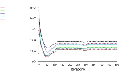
Residual curve for 10mm Residual curve for 20mm lift
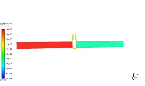
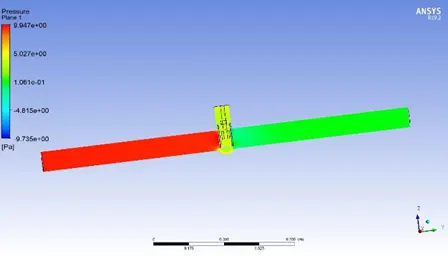
Pressure conture for 10mm lift Pressure conture for 20 mm lift
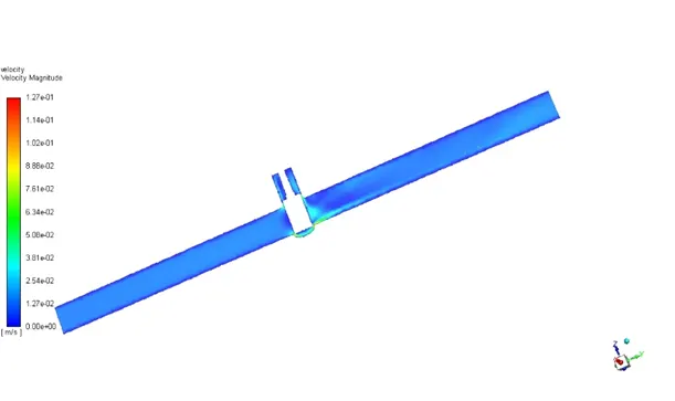
Velocity conture for 10 mm lift
Conclusion
- Ansys fluent helps in study of all results and by applying the parametric study it gives fast and accurate result for different change design modification which gives all results in other parameters ,
- For parametric analysis , we get the result of same design with different modification which give all result no need to run separate simulation for each case , with slight modifications .
- By retaining the each data we can get all the result in each sections , space claim , fluent and result sections ,
- In flow calculation , coefficient of flow and flow factor use to analysis the accuracy of valves by pressure difference and flow rates , by getting the result from flow the manufacturer get the proper result and prevent manufacturing losses
- Better design of gate valves and other valves which result the smoothen the flow in section .