Week 9 - Parametric study on Gate valve.
A. Objective:
To perform a parametric study on the gate valve simulation by setting the opening from 10 % to 80%.
- Obtain the mass flow rates at the outlet for each design point.
- Calculate the flow coefficient and flow factor for each opening and plot the graph.
- Discuss the results of the mass flow rate and flow coefficient.
B. Introduction:
[1] A gate valve controls the media's flow by lifting the gate (open) and lowering the gate (closed). A gate valve's distinct feature is the straight-through unobstructed passageway, which induces minimal pressure loss over the valve.
- Functioning principle:
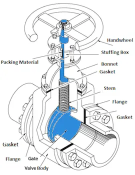
A gate valve's main components are body, seat, gate, stem, bonnet, and actuator (Figure 2). The primary operation mechanism is straightforward. Turning the handwheel rotates the stem, which moves the gate up or down via the threads. They require more than one 360° turn to fully open/close the valve. Lifting the gate from the path of the flow, the valve opens. Lowering the gate to its closed position seals the bore resulting in a full closure of the valve.
For a gate valve, the relationship between the gate's vertical travel and the flow rate is nonlinear, with the highest changes occurring near shutoff. When used to regulate flow, the relatively high velocity of the flow at partial opening results in gate and seat wear, which along with possible vibrations of the gate, shortens the valve's service life.
C. Geometry:
- Given Geometry:
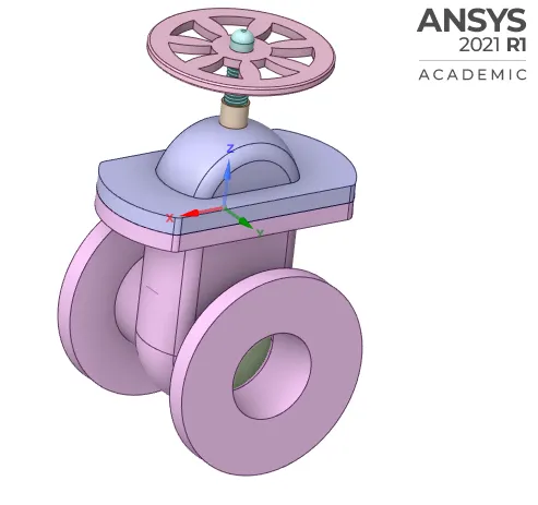
- Extracted Volume:
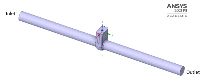
The fluid volume is extracted by parametrizing, after the gate valve is lifted by required distance and is updated again as per the context with required components turned on (suppressed for physics) [2]. Further pressure drop and mass flow rate values are determined for various lift parameters set in design point table through parametric study [3], as discussed further.
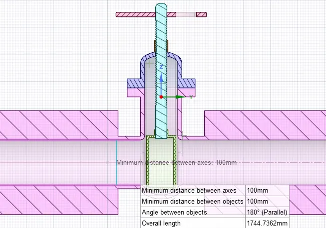
- Maximum lift assumed for this simulation is 100 mm based on internal diameter of pipe i.e 100 mm also considering full flow of fluid without any blockage by the lift gate [4].
D. Meshing Details:
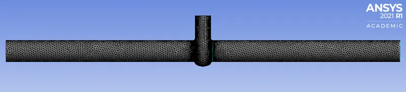
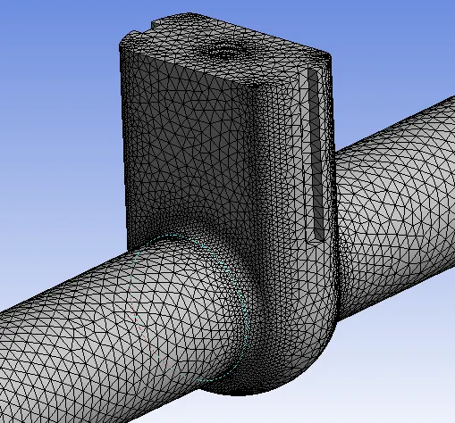
- Mesh Type: Tetrahedral
- Element Size: 10mm
- Nodes: 40475
- Number of Elements: 193311
E. Setup:
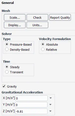
- General:
- Models:
- Viscous Model: k-epsilon (2 eqn)
- k-epsilon model: Realizable
- Near Wall Treatment: Scalable Wall Functions
- Material: Water
- Boundary Conditions:
- Type: Pressure Inlet
- Gauge Total Pressure: 10 Pa
- Initialization: Hybrid
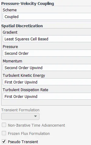
- Solution Methods: Considered default settings set by Ansys
F. Parametric study on the gate valve simulation by setting the opening from 10 % to 80% :
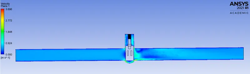
CASE 1: Parametric study on the gate valve simulation by setting the opening at 10% i.e. 10mm lift :
- Section View at 10mm lift:

- Velocity Contour:
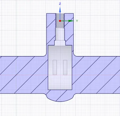
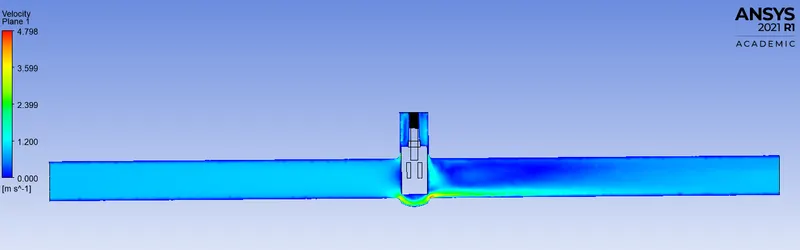
CASE 2: Parametric study on the gate valve simulation by setting the opening at 20% i.e. 20mm lift :
- Section View at 20mm lift:
- Velocity Contour:
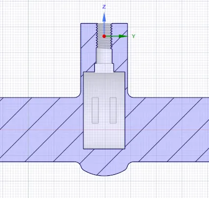
CASE 3: Parametric study on the gate valve simulation by setting the opening at 30% i.e. 30mm lift :
- Section View at 30mm lift:
- Velocity Contour:
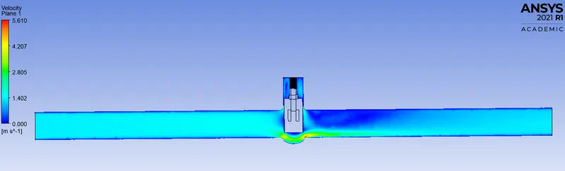
CASE 4: Parametric study on the gate valve simulation by setting the opening at 40% i.e. 40mm lift :
- Section View at 40mm lift:
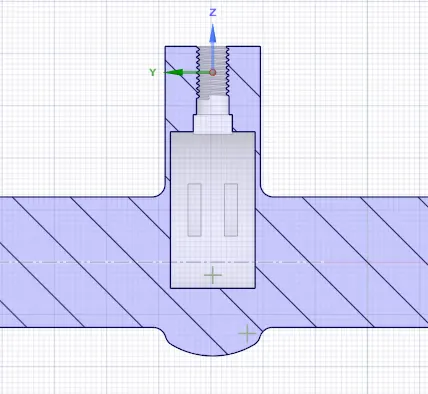
- Velocity Contour:
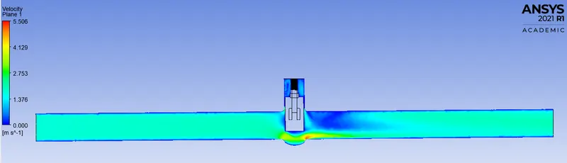
CASE 5: Parametric study on the gate valve simulation by setting the opening at 50% i.e. 50mm lift :
- Section View at 50mm lift:
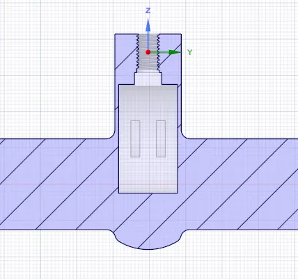
- Velocity Contour:
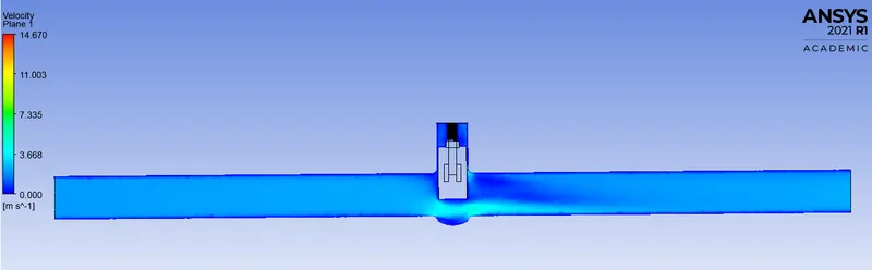
CASE 6: Parametric study on the gate valve simulation by setting the opening at 60% i.e. 60mm lift :
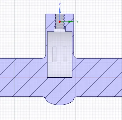
- Section View at 60mm lift:
- Velocity Contour:
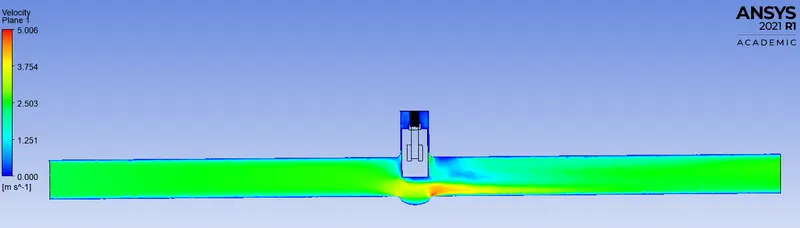
CASE 7: Parametric study on the gate valve simulation by setting the opening at 70% i.e. 70mm lift :
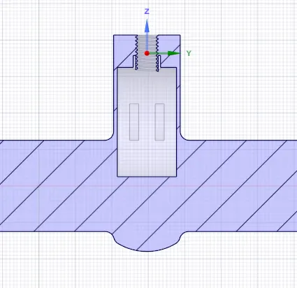
- Section View at 70mm lift:
- Velocity Contour:
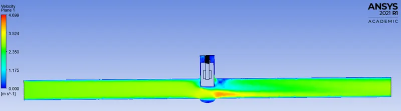
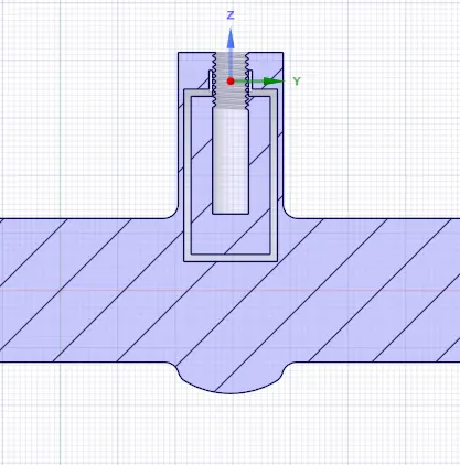
CASE 8: Parametric study on the gate valve simulation by setting the opening at 80% i.e. 80mm lift :
- Section View at 80mm lift:
- Velocity Contour:
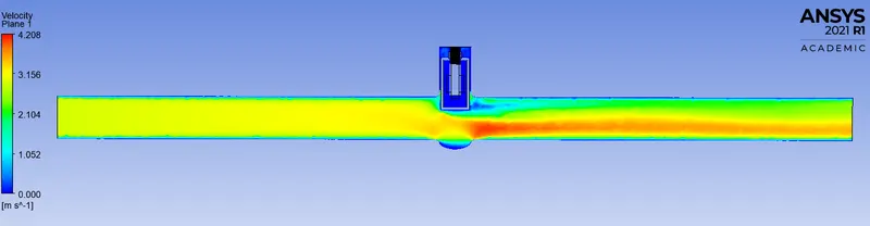
> From cases 6, 7 and 8 fluid can be seen entering lower bonnet region over lower threads of the spindle as shown in their section views respectively.
Hence, following 3 cases are performed for lifts 25 mm, 35 mm and 45 mm as shown further.
CASE 9: Parametric study on the gate valve simulation by setting the opening at 25% i.e. 25mm lift :
- Section View at 25mm lift:
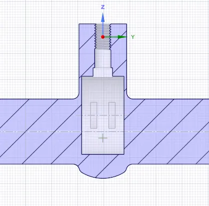
- Velocity Contour:
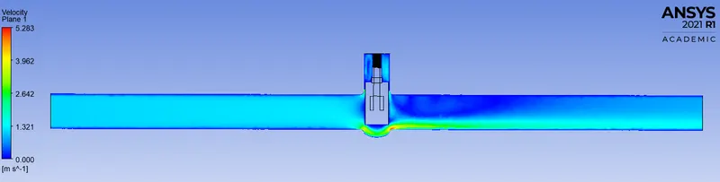
CASE 10: Parametric study on the gate valve simulation by setting the opening at 35% i.e. 35mm lift :
- Section View at 35mm lift:
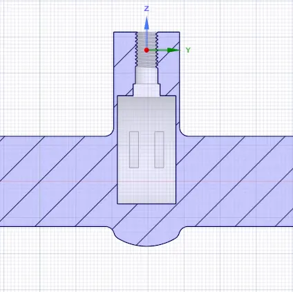
- Velocity Contour:
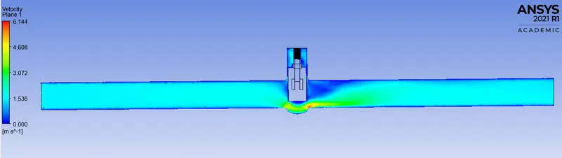
CASE 11: Parametric study on the gate valve simulation by setting the opening at 45% i.e. 45mm lift :
- Section View at 45mm lift:
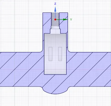
- Velocity Contour:
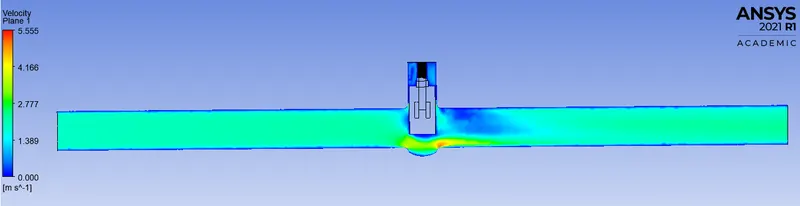
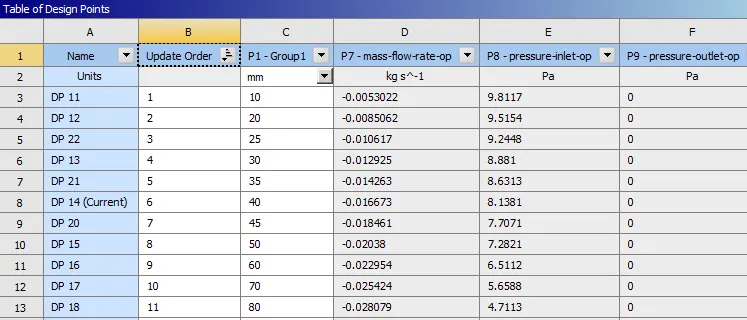
Table of Design points with Mass Flow Rates and Pressure Drop for corresponding lifts through parametric study:
G. Flow coefficient and flow factor for each opening with required graphs:
- The flow coefficient of a device is a relative measure of its efficiency at allowing fluid flow. It describes the relationship between the pressure drop across an orifice valve or other assembly and the corresponding flow rate.
Kv = 0.857 * Cv
Cv = 1.165 * Kv
- Formula to calculate Flow Factor [5]:
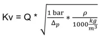
Q = volume flow in m3/h (1 kg/s = 3.6 m3/h) [6]
Δp = pressure drop in bar (1 pa = 1e-5 bar) [7]
ρ = density of the liquid in kg/m3
- Flow coefficient and flow factor for each opening:
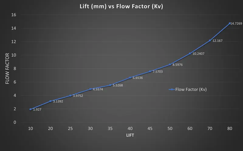
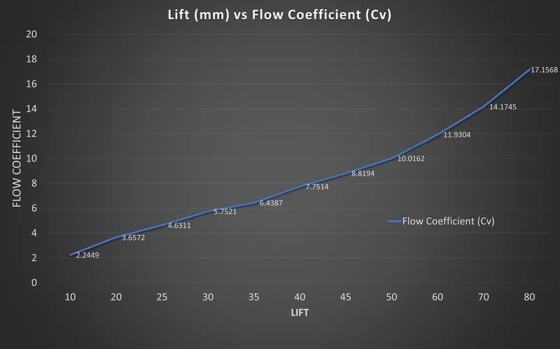
| Lift | Flow Factor (Kv) | Flow Coefficient (Cv) |
| 10 | 1.927 | 2.2449 |
| 20 | 3.1392 | 3.6572 |
| 25 | 3.9752 | 4.6311 |
| 30 | 4.9374 | 5.7521 |
| 35 | 5.5268 | 6.4387 |
| 40 | 6.6536 | 7.7514 |
| 45 | 7.5703 | 8.8194 |
| 50 | 8.5976 | 10.0162 |
| 60 | 10.2407 | 11.9304 |
| 70 | 12.167 | 14.1745 |
| 80 | 14.7269 | 17.1568 |
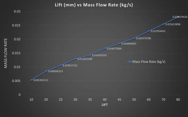
- Lift vs Mass Flow Rate:
- Lift vs Flow Factor:
- Lift vs Flow Coefficient:
- Lift vs Flow Factor and Flow Coefficient compared:
H. Observations:
- Lift and Mass Flow Rate are directly proportional to each other.
- Flow Factor and Flow Coefficient increased as lift was increased accordingly.
- An on/off valve therefore only has one Kv factor while control valves have Kv factors for each position.
- When selecting the correct valve type and size, various operands can be decisive.
References:
[1] https://tameson.com/gate-valve.html
[2] https://skill-lync.com/knowledgebase/gate-valve-parametric-study-help
[3] https://skill-lync.com/knowledgebase/parametrizing-in-ansys-fluent
[4] https://www.slideshare.net/TravisOsburn/scv-expanding-gate-valves
[5] https://www.burkert.in/en/Service-Support/Support/Glossary/Fluid-Calculator
[7] https://www.unitconverters.net/pressure/pascal-to-bar.htm