Week 9-Creation of 1D Connectors Challenge
Objective –
Mesh the given component by following given quality parametes.
Target element size = 5 units
|
S.N |
Quality Criteria |
Value |
|
1 |
Aspect Ratio |
5 |
|
2 |
Skewness |
45 |
|
3 |
Warping |
15 |
|
4 |
Taper |
0.5 |
|
5 |
Min. Length |
2 Units |
|
6 |
Max. Length |
8 Units |
|
7 |
Min angle Quad |
45 |
|
8 |
Max angle Quad |
135 |
|
9 |
Min angle Tria |
30 |
|
10 |
Max angle Tria |
110 |
|
10 |
Tria % |
15 |
Create connector and attach the various parts of the given model
- Right Rail 2 & Front truss 1 :- Seam-Quad(angled+capped+L)
- Left Rail 2 & Front truss 1 :- Quad elements
- Front truss 2, Front truss 1 & Right Rail 1 :- Spot weldwith 2 Layers and 5 mm Diameter
- Front truss 2, Front truss 1 & Left Rail 1 :- Hexa (Adhesive)
- Rear truss 2 & Right Rail 2 :- Bolt Connector
- Rear truss 2 & Left Rail 2 :- Bolt Connector
- Right Rail 1 & Right Rail 2 :- Spot-weld with Rigid Elements
- Left Rail 1 & Left Rail 2 :- Spot-weld withSpring Elements
- Rest all the component left Join them with suitable connectors
Procedure –
- First I have imported model to hypermesh work bench.
- Then I meshed all the components with the given quality parameters after specifying in criteria file setting.
- Then I went for to apply connector to each pair of components.
- For Seam Quad Angled capped L, I went 2D – Connectors – Seam – in type specify the Angled capped L – define spacing and tolerance as required – in location change to node list for selection of node – in components select two components that you want to apply connector – give hits on create.
- Once it created on your model, your mesh will get disturb. For this I have remeshed again to meet quality parameters.
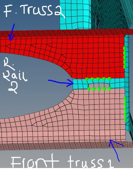
- Similarly for quad elements, I have followed same process only I have changed Angled capped L to quad.
- For spot weld, I went 2D connector – spot – in type specify as weld from option – in location define your nodes that you want put – in component select two component you want to weld – define tolerance and diameter of spot weld – give hit on the create to add connector. Once you will get connector you can go for other two components to spot weld. For spot welding of three components is not possible, that’s the reason I went for spot welding of first pair, and another pair in second.
- For selecting nodes from component, you can refer marks that given to you.
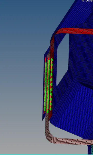
- For Hexa adhesive, I went 2D connector – seam – In type selection changed to Hexa adhesive – In location I have choosed nodes as per mark given – In components I have selected two components – then give hit on create.
- Later on I went for another two components since we had to apply adhesive to three components.
- To apply bolt connector in between two components, go to 2D connector – bolt – in type select bolt general – select node in location, where you apply bolt – in component select two components that you want fix by bolt – specify tolerance – in hole section specify “create hole, if done” since we don’t have existing hole in our component – give hit on create – you will be done with bolt connector.
- After getting bolt connector, I remeshed these two component again to meet quality parameters.
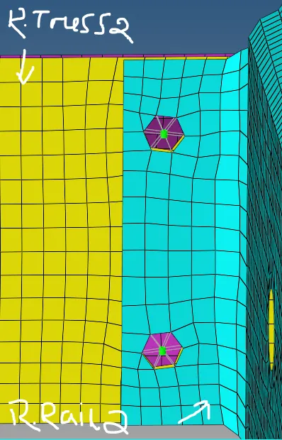
- For another bolt connector also I have followed same process, in node selection I took node from left rail and in component I choosed left rail and rear truss 2, and then give hit on create. Also these two parts remeshed since after applying bolt connector mesh got disturbed.
- For spot weld rigid elements, same process I have followed as same as spot weld given in front truss 1 & 2, right rail 1. Only change is in type instead of weld we have to select rigid and in components, need to select required components.
- Similarly for Spot weld spring also we have to follow same process.
- After deploying all connectors to its given components, still there were left some components which are not connected.
- On these components I have applied spot weld like as in between rear truss 1 & 2, front truss 1 & reinforcement plate and front truss 2 & reinforcement plate.
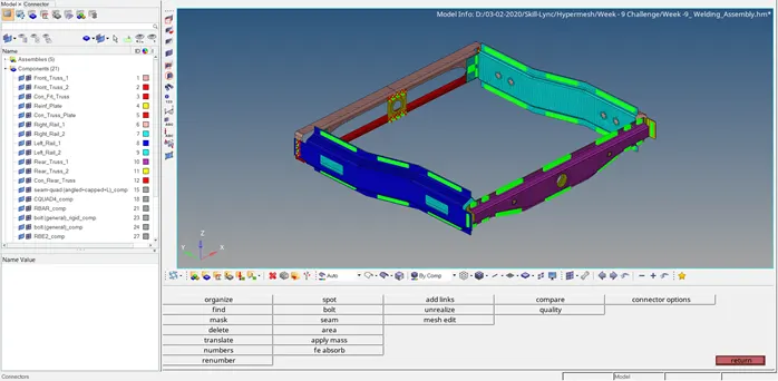
- While deploying connectors to components, it should be in green colour. It represents connectors are realized. If it is in red we have to apply it again, represents didn’t realize.
Final Model –