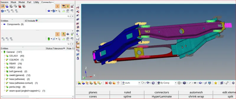
Week 9-Creation of 1D Connectors Challenge
WEEK-9
CREATING CONNECTORS IN HYPERMESH
OBJECTIVE:
- To mesh the given geometry according to quality parameters
- To create connectors at the different joints and attach the various parts in the given model
Quality Criteria Used:
Target Element size - 5 Units
|
S.No |
Quality Criteria |
Value |
|
1 |
Aspect Ratio |
5 |
|
2 |
Skewness |
45 |
|
3 |
Warping |
15 |
|
4 |
Taper |
0.5 |
|
5 |
Min. Length |
2 Units |
|
6 |
Max. Length |
8 Units |
|
7 |
Min angle Quad |
45 |
|
8 |
Max angle Quad |
135 |
|
9 |
Min angle Tria |
30 |
|
10 |
Max angle Tria |
110 |
|
10 |
Tria % |
15 |
PROCEDURE:
- Import Geometry: Go to File >> Import >> Model/Geometry
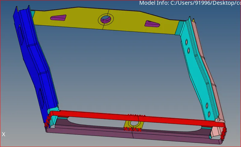
Imported geometry
Mesh Generation:
- Mesh each surface individually according to quality parameters
- Improve mesh flow and clear off elements and opposite trias
- It is important to note that creation of some connectors destroy mesh flow
- After generating the connectors, the mesh needs to be modified for good mesh flow and satisfying all quality parameters
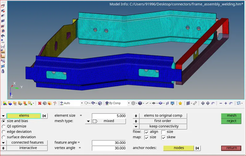
Meshed geometry
CONNECTORS:
Connectors are elements that are used to represent connections between other geometrical entities. Hypermesh offers different types of connectors in 1D, 2D, and 3D for this purpose. It includes weld, adhesives, bolts, area contact
- Right_Rail_2 & Front_truss_1: - Seam-Quad (angled + capped + L)
- Select 1D/2D → Connectors → Seam option. Select the required options as shown below and create
- Tolerance value is the distance between 2 components
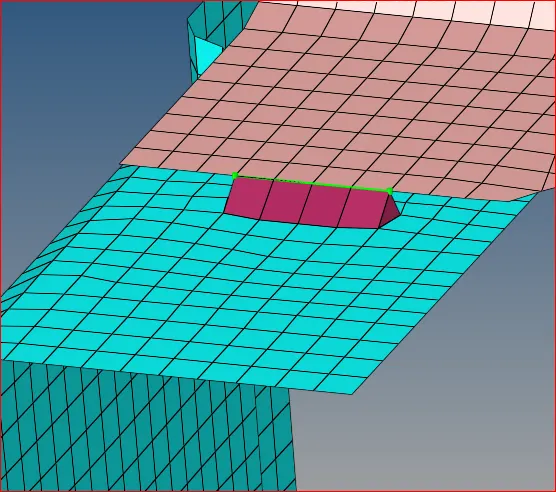
- The green line represents a successful connection
- We need to remesh that area where the connection is realized
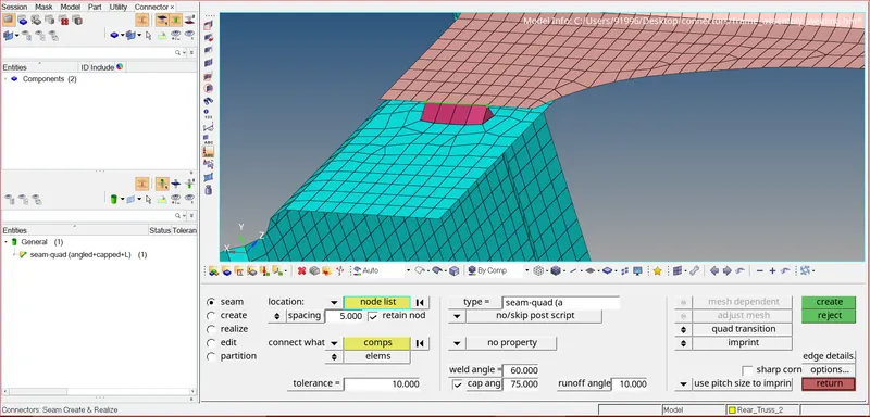
Connection is realized but the mesh is distorted
- Clear all the trias possible and rectify all quality issues also
- We need to do this whenever we create any connection
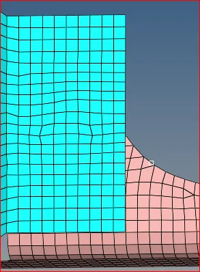
Mesh flow after re-meshing
- Left_Rail_2 & Front_truss_1: - Quad elements
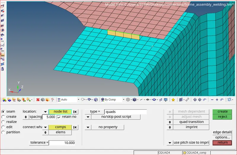
Seam Quads connection is realized
- Front_truss_2, Front_truss_1 & Right_Rail_1: - Spot weld with 2 Layers and 5 mm Diameter
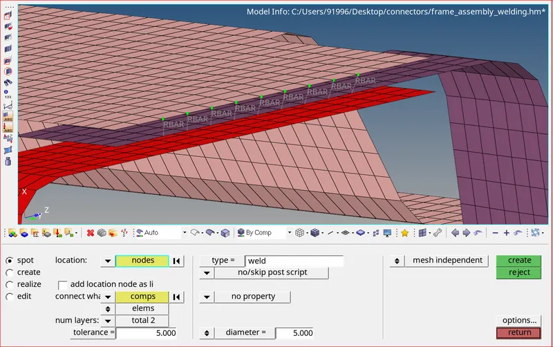
1st layer of spot weld connection
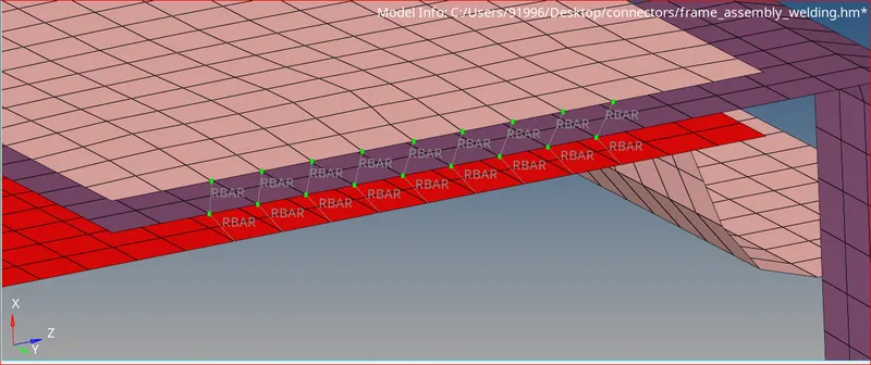
2nd layer of spot weld connection
4. Front_truss_2, Front_truss_1 & Left_Rail_1: - Hexa (Adhesive)
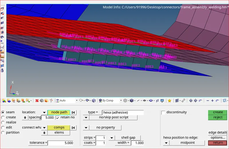
Hexa Adhesive connection realized between 3 components
- Rear_truss_2 & Right_Rail_2: - Bolt Connector
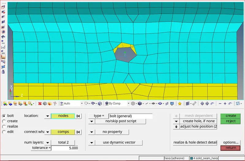
General Bolt connection
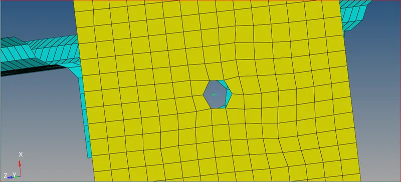
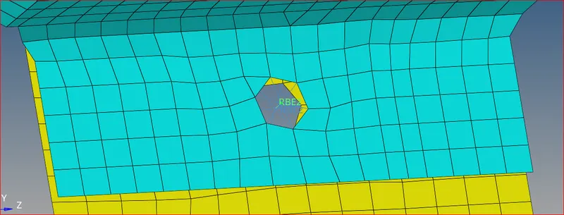
Mesh flow after re-meshing
- Rear_truss_2 & Left_Rail_2: - Bolt Connector
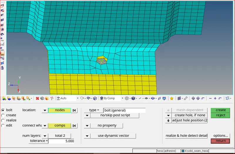
General Bolt connection
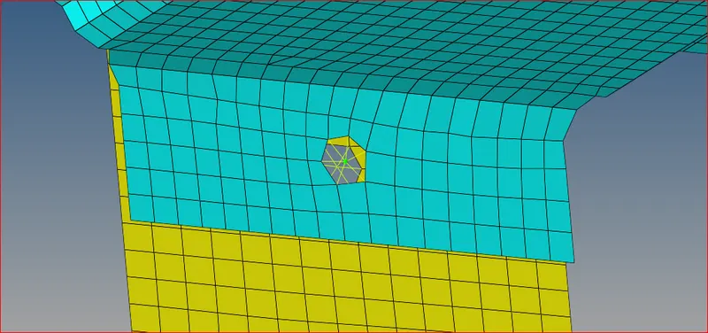
Mesh flow after re-meshing
- Right_Rail_1 & Right_Rail_2: - Spot-weld with Rigid Elements
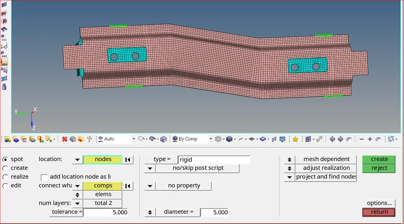
Spot weld with rigid type connections
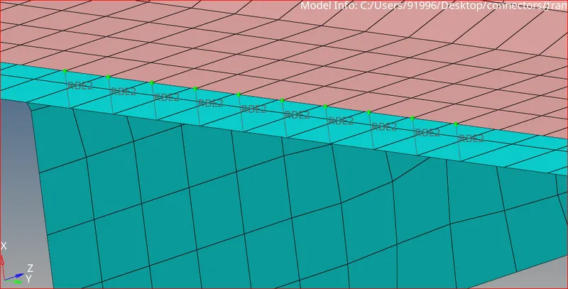
RBE2 elements
- Left_Rail_1 & Left_Rail_2: - Spot-weld with Spring Elements
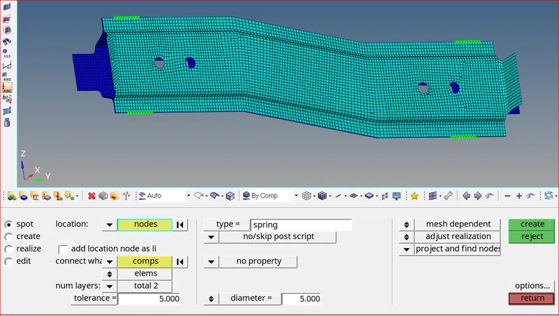
Spot with spring elements are realized
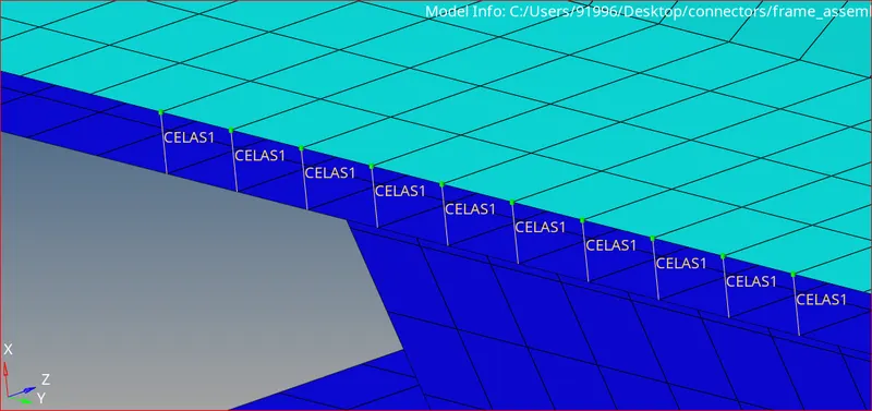
Spring (CELAS1) Elements
- CWeld (General):
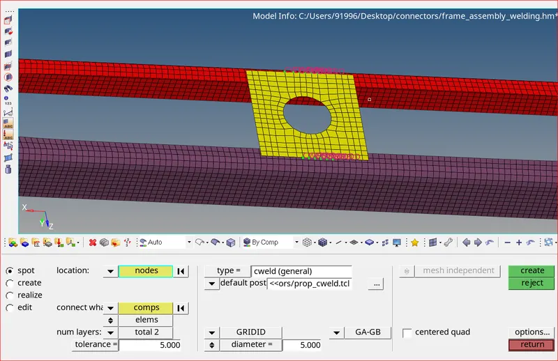
Cweld general connection realized
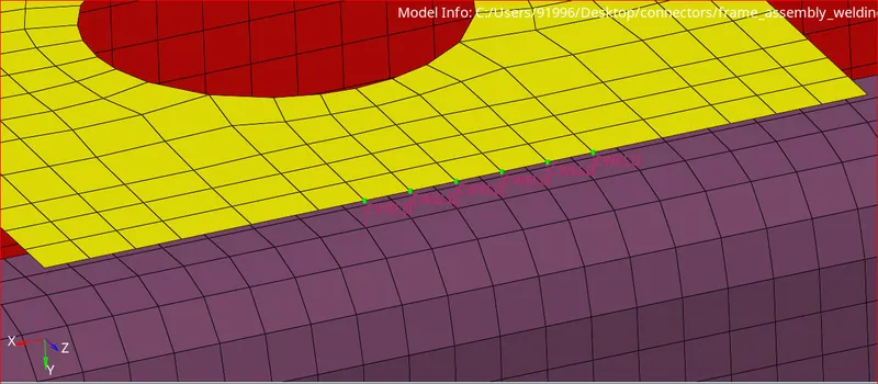
Cweld elements
10. Spot Penta (mig) Connection:
- This connection consists of a combination of RBE3 rigid elements and Penta mig solid components
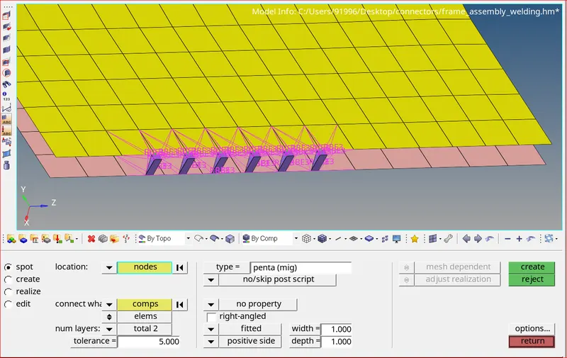
Penta (mig) Connection realized
Note:
- RBE3 elements usually give us better results than RBE2 elements
- RBE2 are rigid elements that induce excessive stiffness to the model and they will give us bad results
- Whereas RBE3 elements are not actually rigid elements, they only transfer the load without any stiffness in the model.
11. Rigid Links:
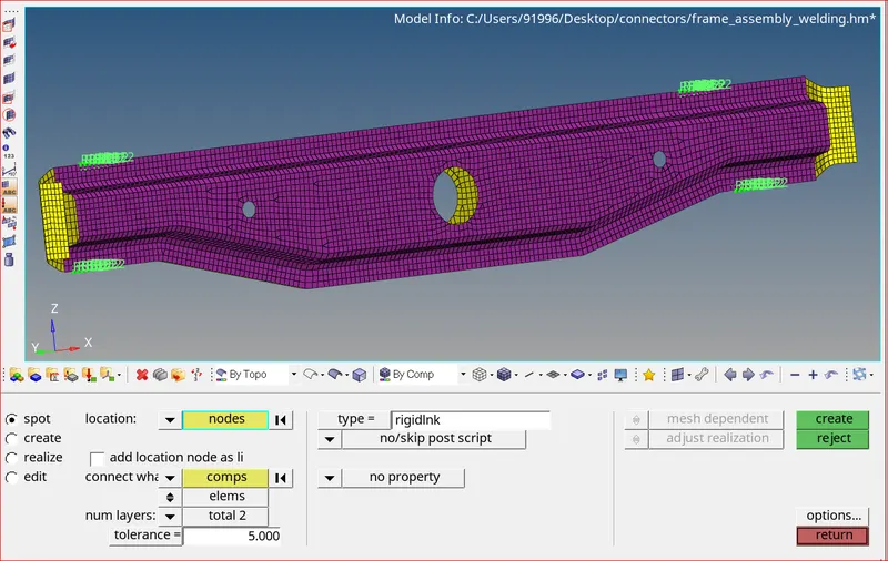
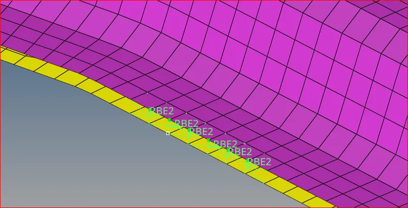
Rigidlnk connection realized RBE2 rigid elements
12. Seam Hexa Adhesive Contact Connection:
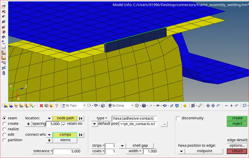
Hexa Adhesive Contact Connection Realized
Learning Outcome:
- Aware of all the quality criterias and quality parameters during mesh generation.
- Improved mesh flow and removed trias, rotating quads to achieve better mesh flow
- Understood how to realize various connections using hypermesh
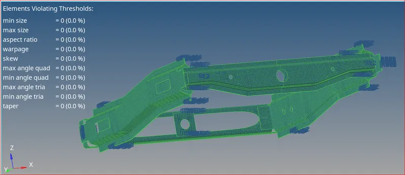
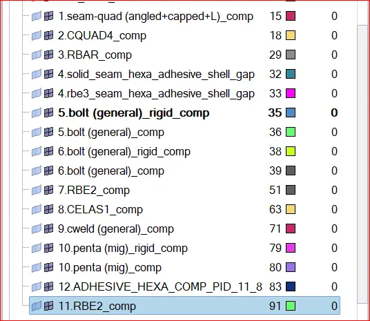
Quality index Connections under Model tab
Conclusion:
All the required connections are successfully realized for the given geometry. The mesh flow is good. There are no quality issues.