Week 9-Creation of 1D Connectors Challenge
Aim - To create Connectors for the given component.
Theory -
- What are Connectors?
In Hypermesh Connectors are Used to join 2 or different components In an assembly. It defines the mechanics of how 2 or more components are joined together. Connectors help in simulating the defined joinery without actually realizing it in a CAD model. It creates a Simpler model without compromising on the results of the simulation.
Various types of connectors are -
- Spot weld
- seam weld
- Adhesive
- Bolt Connections
Depending on the model we can use all these options.
- How to identify If a connection is realized or not?
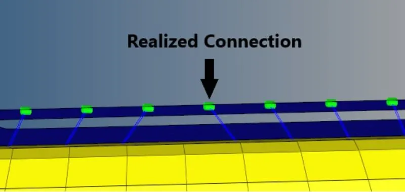
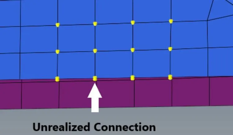
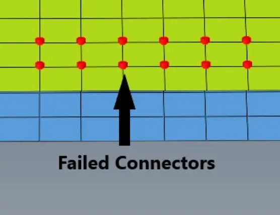
Realizing a connection is a very crucial part of doing connections in an FEA model. If a connector failed to realize then the simulation is going to fail. There are 3 stages of connectors
- Realized Connector - A successful connection is shown with a green color Indicator.
- Unrealized Connectors - Unrealized Connectors are shown with a yellow indicator
- Failed connectors - Failed connectors are shown with a red color indicator.
Quality criteria for meshing
Target Element size - 5 Units
|
S.N |
Quality Criteria |
Value |
|
1 |
Aspect Ratio |
5 |
|
2 |
Skewness |
45 |
|
3 |
Warping |
15 |
|
4 |
Taper |
0.5 |
|
5 |
Min. Length |
2 Units |
|
6 |
Max. Length |
8 Units |
|
7 |
Min angle Quad |
45 |
|
8 |
Max angle Quad |
135 |
|
9 |
Min angle Tria |
30 |
|
10 |
Max angle Tria |
110 |
|
10 |
Tria % |
15 |
Connector Positions -
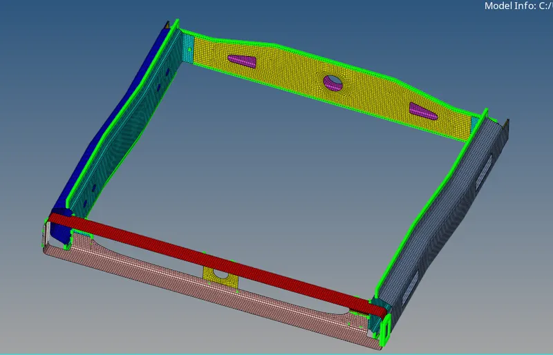
1. Right_Rail_2 & Front_truss_1:- Seam-Quad(angled+capped+L)
2. Left_Rail_2 & Front_truss_1:- Quad elements
3. Front_truss_2, Front_truss_1 & Right_Rail_1:- Spot weld with 2 Layers and 5 mm Diameter
4. Front_truss_2, Front_truss_1 & Left_Rail_1:- Hexa (Adhesive)
5. Rear_truss_2 & Right_Rail_2:- Bolt Connector
6. Rear_truss_2 & Left_Rail_2:- Bolt Connector
7. Right_Rail_1 & Right_Rail_2:- Spot-weld with Rigid Elements
8. Left_Rail_1 & Left_Rail_2:- Spot-weld with Spring Elements
9. Rest all the components left Join them with suitable connectors
Model -
Procedure -
- Import the Geometry using the Import Option.
- Create a Mesh on the different components according to the given quality criteria.
- For different types of connections follow the given criteria.
A. Steps to be followed to create Seam - Quad (angled+Capped+L) Weld:
- Select 1D/2D → Connectors → Seam option.
- Now select the location, where the Weld has to be created, by clicking the “node list”.
- Tick the checkbox of the “retain nodes” option, to retain the position of the nodes, while creating and realizing a connector.
- Specify the “spacing” value and select the “comps” option under “connect what”, in order to create the weld between those two components.
- Specify the “tolerance” value, based on the distance between the two components.
- Select the type “seam-quad (angled+capped+L)”.
- Click on the “create” button, to create the seam weld
B. Steps to be followed to create Seam - Hexa Adhesive Weld:
- Select 1D/2D → Connectors → Seam option.
- Now select the location, where the Weld has to be created, by clicking the “node list”.
- Tick the checkbox of the “retain nodes” option, to retain the position of the nodes, while creating and realizing a connector.
- Specify the “spacing” value and select the “comps” option under “connect what”, in order to create the weld between those two components.
- Specify the “tolerance” value, based on the distance between the two components.
- Select the type “Hexa (adhesive)”.
- Click on the “create” button, to create the seam weld
Spot welding is a resistance welding process that is used primarily for welding two or more metal sheets together by applying pressure and heat to the weld area. Heat for the welding process will be obtained from resistance to electric current. Realized spot weld in HyperMesh will represent the connection between the components.
Steps to be followed to create Spot Weld:
- Select 1D/2D → Connectors → Spot option.
- Now select the location, where the Weld has to be created, by clicking the “node list”.
- Tick the checkbox of the “retain nodes” option, to retain the position of the nodes, while creating and realizing a connector.
- Specify the “spacing” value and select the “comps” option under “connect what”, in order to create the weld between those two components.
- Select the number of layers(Number of Components) to be welded, under the “num layers” option.
- Specify the “tolerance” value, based on the distance between the two components.
- Select the type “weld”.
- Click on the “create” button, to create the spot weld
Conclusion -
- Through this project, the knowledge for applying connectors is gained. and information about different types of connectors is acquired.