Week 9-Creation of 1D Connectors Challenge
Week 9
Aim- Creating 1D connections for the assembly.
Google drive Link-https://drive.google.com/file/d/147Us5JRiPIqOnZSho9ghGvqIL6s8Bt1/view?usp=share_link
Step 1- Import the Geometry.
Step 2 – Checking for the number of components.
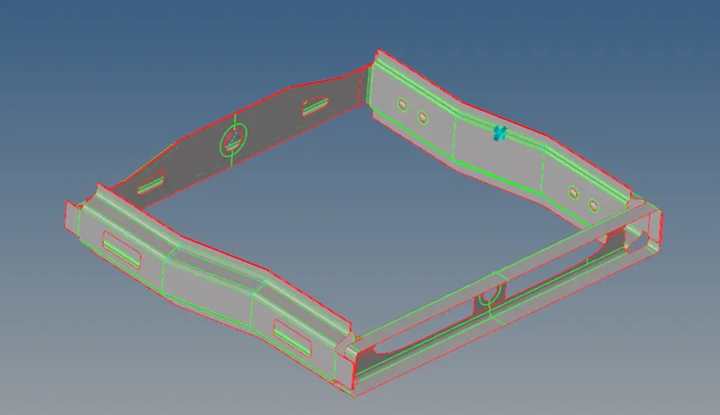
Fig 1 – CAD of Assembly
Step 3 - Added the quality criteria as per the question from 2D- element clean up- quality edit criteria.
Step 4 - Meshing on the different components one by one from 2D - auto mesh- element size- 5 units- element type - mixed.
Step 5 - Improved the elements from 2D - quality index - cleanup tools.
Step 6-Converted all the components into a single assembly from tools -assemblies - given assembly name- Selected all the components - create.
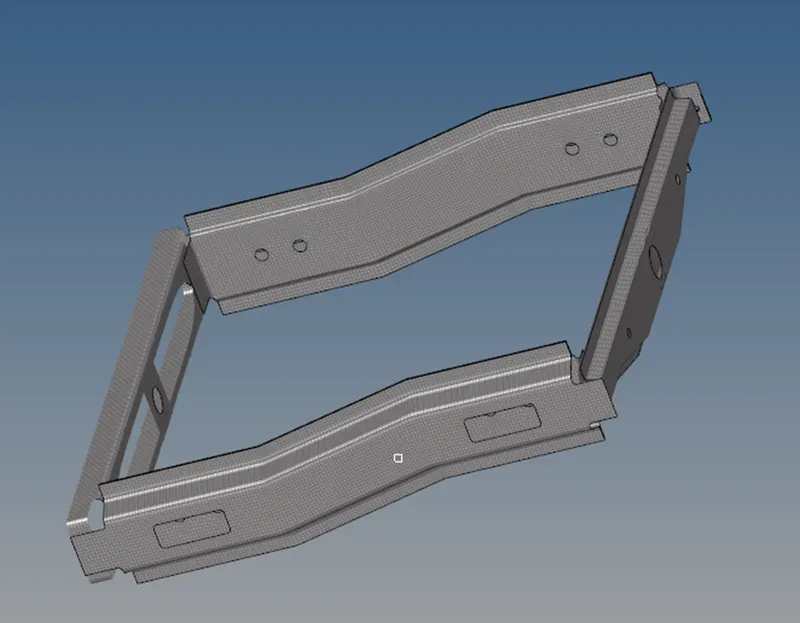
Fig 2 - Meshing of the assembly.
Connections for assembly.
- Seam quad (angle +capped +L)
Step 1- Turned on the Right rail 2 and front truss 1.
Step 2 - Added the seam weld connection at the common joint from 2D - Connections Seam- Selected the nodes - Selected the two components- Spacing = 5 -Search tolerance =50- Type = Seam Quad (angle+capped +L)
Step 3 - Added and assigned the property for weld- create.
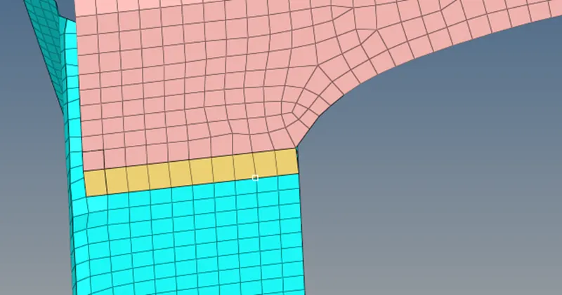
Fig 3- Seam Quad (angle +capped +L) location
- Seam Quad
Step 1- Turned on the Left rail 2 and front truss 1.
Step 2 - Added the seam weld connection at the common joint from 2D - Connections Seam- Selected the nodes - Selected the two components- Spacing = 4 -Search tolerance =50- Type = Quads
Step 3 - Added and assigned the property for weld- create.
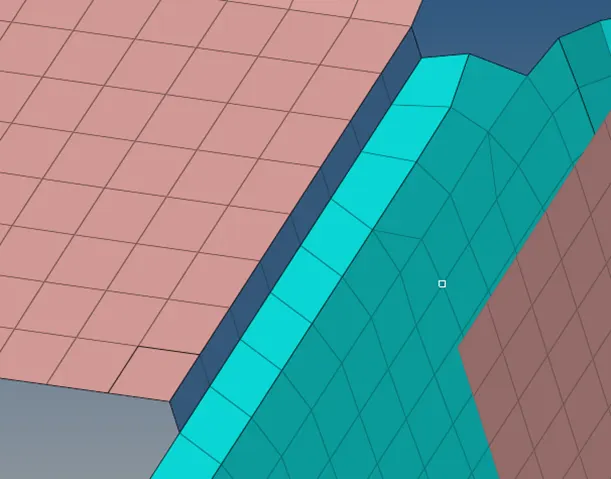
Fig 4 - Seam Quad location.
- Spot weld 2 layers with 5 mm diameter.
Step 1- Turned on the Front truss 2 and front truss 1 and right rail 1.
Step 2- Connected the components using connectors from, 2D- Connectors-spot- Selected the nodes- selected the components - search tolerance = 50 -number of layers = 2 - Diameter =5 create.
Step 3 - Added and assigned the property for weld- create.
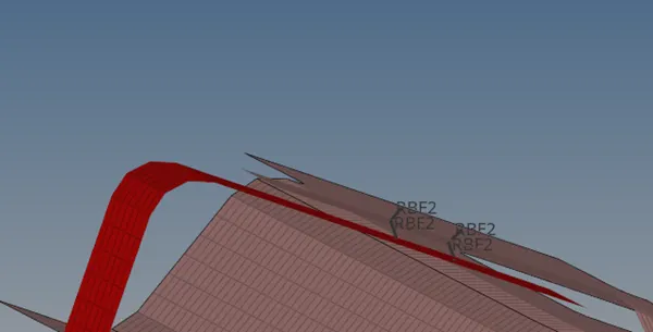
Fig 5 - Spot weld location.
- Hexa (Adhesive)
Step 1- Turned on the Front truss 2 and front truss 1 and right rail 1.
Step 2- Connected the components using connectors from, 2D- Connectors-Area- Selected the elements- selected the components - search tolerance = 50.
Step 3 - Added and assigned the property for weld- create.
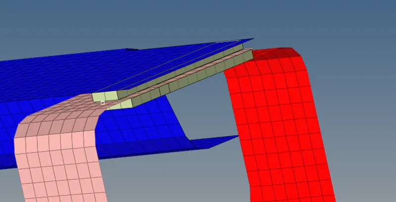
Fig 6 - Location of Hexa adhesive
- Bolt Connector.
Step 1- Turned on the Rear trust 2 and Right rail 1.
Step 2- Connected the components using connectors from, 2D- Connectors-Bolt- Selected the elements- selected the component- search tolerance = 50- Check for create hole , if none- Type = Bolt (general)
Step 3 - Added and assigned the property for weld- create.
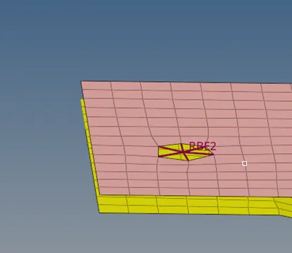
Fig 7 - Location of bolt
- Spotweld with Right elements.
Step 1- Turned on the Right rail 1 and Right rail 2.
Step 2- Connected the components using connectors from, 1D- Spot weld-Using nodes - Selected the independent nodes -selected the dependent nodes- element configuration = Rigid - search tolerance = 50- Weld location- create.
Step 3 - Added and assigned the property for weld- create.
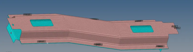
Fig 8 - Location of spot weld.
Performed similar connections on the different components.
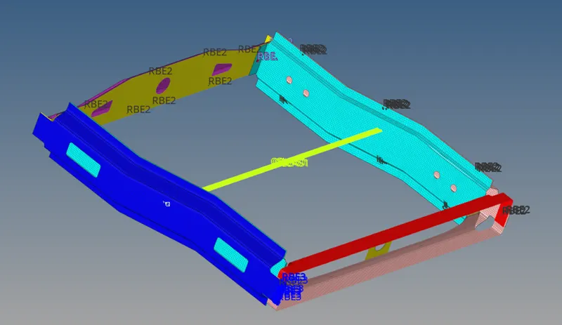
Fig 9 - Assembly with connectors.
Conclusion
- We learned about the different connection and the application.
- We learned about the constraints of the software.