Week 9-Creation of 1D Connectors Challenge
Procedure:
Step 1: Importing the geometry
- To import the geometry, go to file → Import → Import Solver Deck→ File Type: Optistruct → File: frame_assembly_welding.hm → Import.
The CAD model image is shown below with the subcomponents highlighted in different colours.
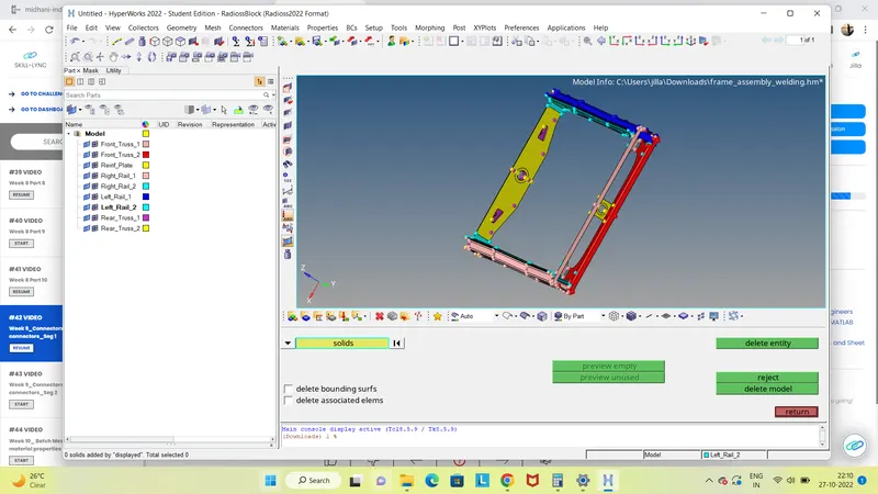
- After importing the geometry, the geometry is checked for any missing surfaces or any other errors and then correct it.
- The given components are already midsurfaces or are lacking thickness, so there is no need to create midsurfaces.
Step 2: Setting the Criteria and Topology cleanup
- We input the given criteria into the HyperWorks software for the respective model using the options
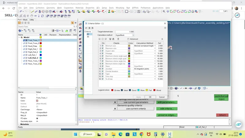
- Figure: Parameter file
We also save them to be used later, if required. - Then we remove the solids using the option delete → Solid → Select solid → delete entity.
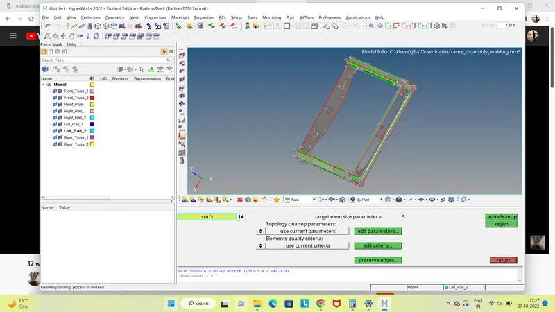
- Prior to meshing we do Geometry or Topology Clean-up in which we check for any free lines, unfilled surfaces and other errors.
- Toggle the unwanted lines(other than Feature lines) for better meshing.
- Remove the surface fillets having maximum radius less than the minimum mesh length using the option defeature → surf fillets → select the surfaces → min radius=0.1, max radius= min mesh length → find → delete.
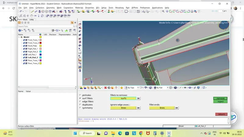
- Figure: Model after Topology clean-up
-
Step 3: Meshing
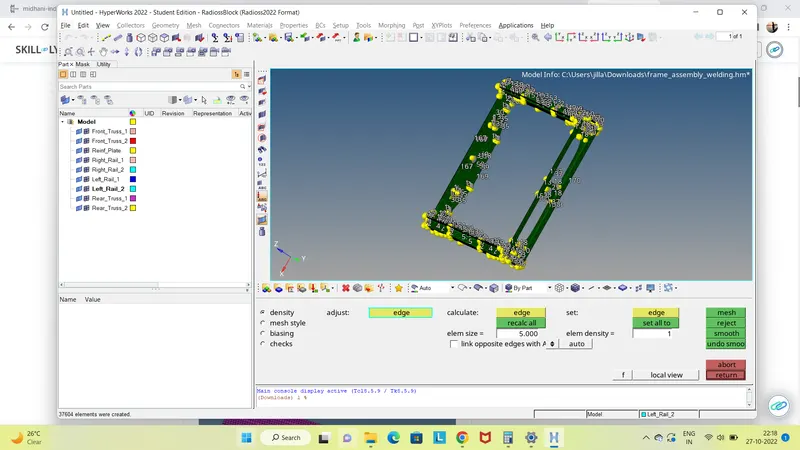
- There are two ways by which we can generate mesh on the given model. First one, is to select all the components and mesh them at once.We can do it by the batchmesh option in 2D panel.
2D → automesh → Batchmesh/QI optimize → select criteria as well as parameter file saved → Select surface → mesh.
However, this may consume quite a bit of time depending upon the system specifications.
The second method is exactly the same but here we will be batchmeshing each component separately so as to reduce the load on the computer. I have chosen the latter. - I batchmeshed each component separately and corrected the quality deviations(if any) along with it.
-
Step 4: Quality checking
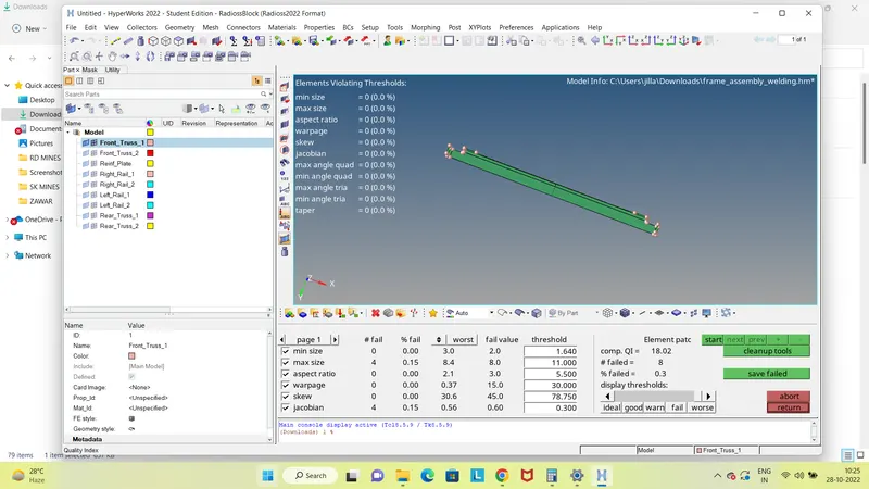
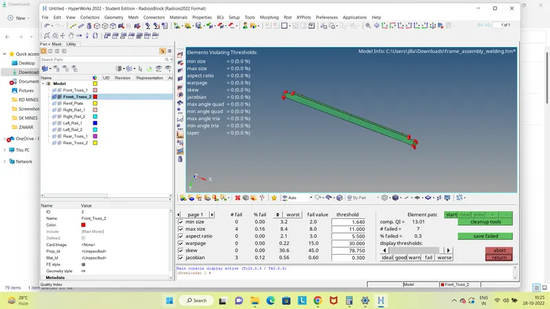
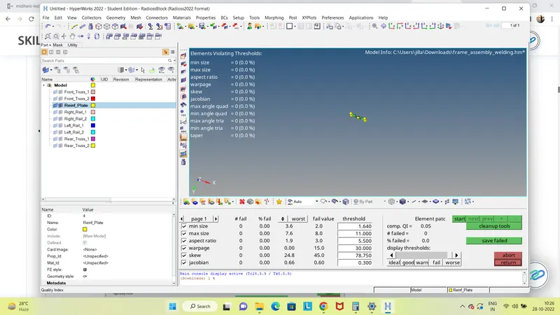
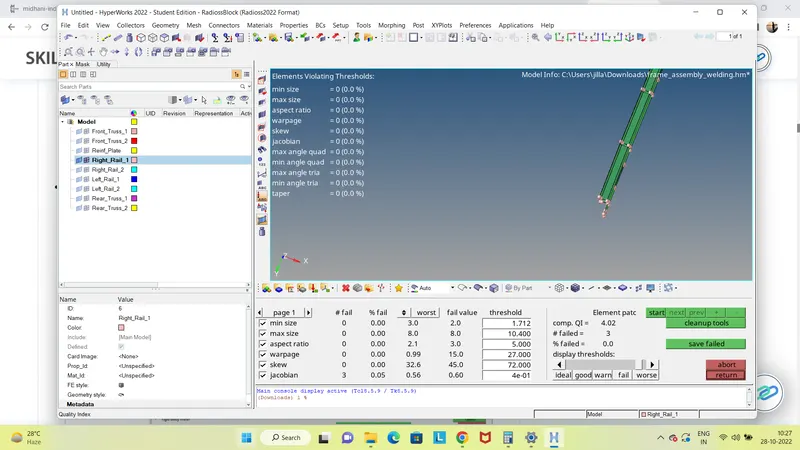
- Once after completing the mesh we need to check and ensure that the mesh so generated is as per the given quality criteria.
- For this we use the option 2D → qualityindex as well as Tool → check elems. There might be deviations in some or all of the quality criteria which we need to correct by using the various options available in the cleanup tool options available in the qualityindex.
-
Step 5: Creating 1D Connectors
- This is the most important step as far as this challenge is concerned.In this challenge,we are given a frame in which there are no connection among the components.Hence,after generating the mesh, we need to connect them using the 1D connectors as specified in the question.
1.Right_Rail_2 & Front_truss_1:- Seam-Quad(angled+capped+L)
- To create a Seam-Quad(angled+capped+L) connector between the components, use the option
1D → connectors → seam → choose type: seam-quad(angled+capped+L), location: node path, spacing= Target element size, select components, weld angle=45, cap angle=60, use avg mesh size to imprint → create
Choose the tolerance value as per requirement. 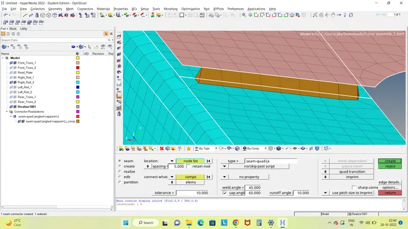
-
Figure: Connector after correcting the mesh flow
2. Left_Rail_2 & Front_truss_1:- Quad elements
To create a Quad connector between the components, use the option
1D → connectors → seam → choose type: quads, location: node path, spacing= Target element size, select components, use avg mesh size to imprint → create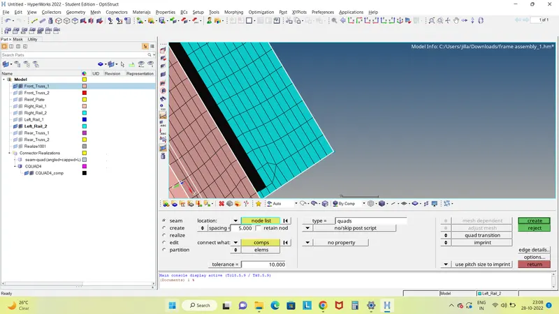
-
Figure: Left_Rail_2 & Front_truss_1 with connector after correcting meshflow
3. Front_truss_2, Front_truss_1 & Right_Rail_1:- Spot weld with 2 Layers and 5 mm Diameter
- Figure: Front_truss_2, Front_truss_1 & Right_Rail_1
To create Spot weld with 2 Layers and 5 mm Diameter among the components, use the option
1D → connectors → spot → choose type: weld, location: nodes, select components, num Layers: total 2, diameter 5 → create 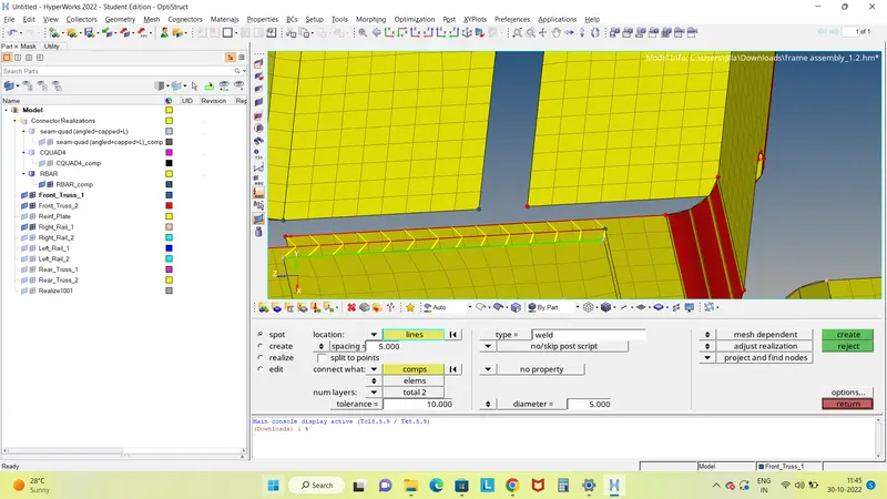
-
Figure: Front_truss_2, Front_truss_1 & Left_Rail_1 without connector
To create a Hexa(adhesive) among the components, use the option
1D → connectors → seam → choose type: hexa(adhesive), location: node path, spacing= Target element size, select components → create 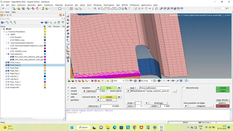
- Figure: Rear_truss_2 & Right_Rail_2 before connector
To create a Bolt between the components, use the option
1D → connectors → bolt → choose type: bolt(CBAR), location: nodes, select components, create hole, if none → create 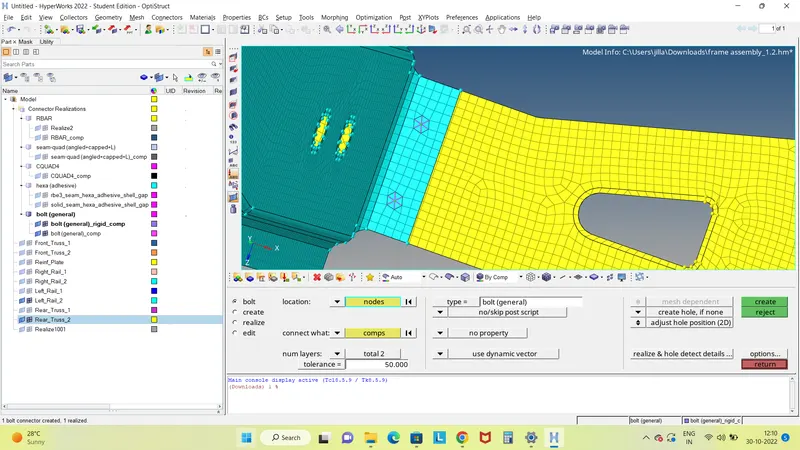
- There are two ways by which we can generate mesh on the given model. First one, is to select all the components and mesh them at once.We can do it by the batchmesh option in 2D panel.
- igure: Right_Rail_1 & Right_Rail_2 without connector
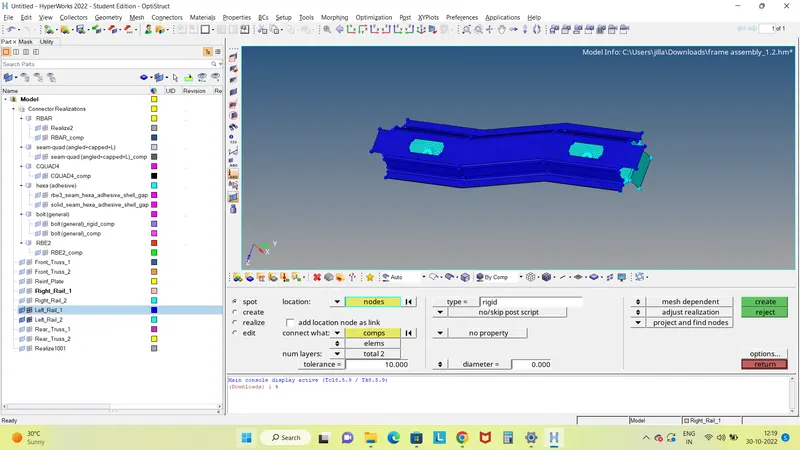
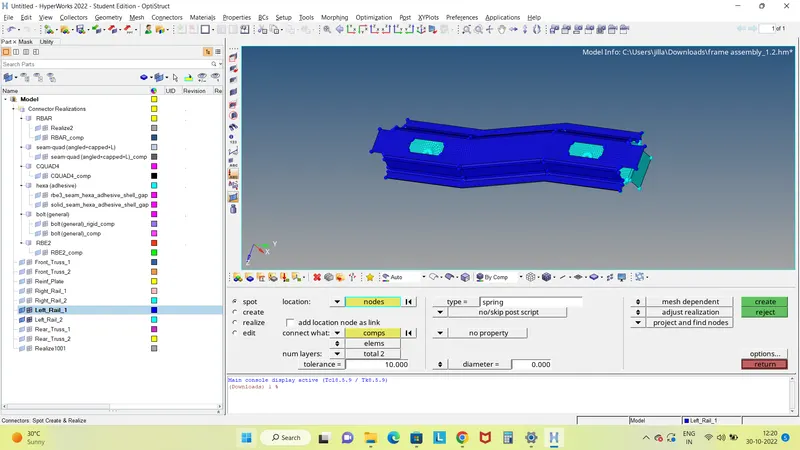
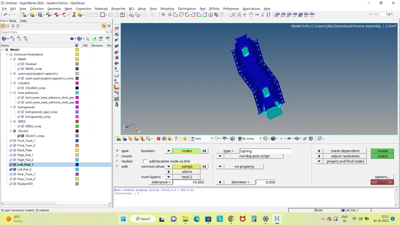
To create Spot weld with Rigid Elements between the components, use the option
1D → connectors → spot → choose type: rigid, location: nodes, select components, num Layers: total 2, diameter 5 → create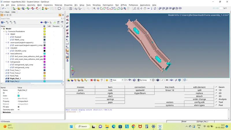
-
Figure:Reinforcement plate, Front_truss_1,Front_truss_2 connected
5.Results:
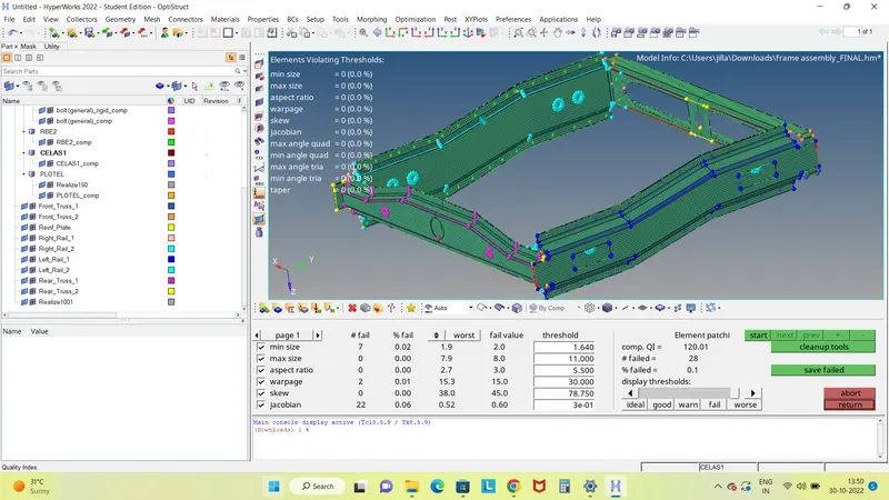
- Generated mesh on the given geometry as per the required quality parameters using HyperWorks.
- Connected the components of the given model using suitable connectors.
- The Final mesh with connectors is shown below
6.Conclusions:
- This challenge helped me to understand about various 1D connectors available in HyperWorks and their uses.
- This challenge also helped me to have in hand experience with the various connectors in HyperWorks and taught me the imporatance of connectors in a model.