Week 9-Creation of 1D Connectors Challenge
OBJECTIVE:
To mesh the given geometry and create 1D connectors at desired locations using Hypermesh.
The following connections have to be realized in each respective component
1. Right_Rail_2 & Front_truss_1:- Seam-Quad(angled+capped+L)
2. Left_Rail_2 & Front_truss_1:- Quad elements
3. Front_truss_2, Front_truss_1 & Right_Rail_1:- Spot weld with 2 Layers and 5 mm Diameter
4. Front_truss_2, Front_truss_1 & Left_Rail_1:- Hexa (Adhesive)
5. Rear_truss_2 & Right_Rail_2:- Bolt Connector
6. Rear_truss_2 & Left_Rail_2:- Bolt Connector
7. Right_Rail_1 & Right_Rail_2:- Spot-weld with Rigid Elements
8. Left_Rail_1 & Left_Rail_2:- Spot-weld with Spring Elements
PROCEDURE:
Setting up model
- Import the .hm model and the connector points in the model tree are hidden while meshing
- Each individual component is separated and meshed seperately.
- If required, the components can be cleaned for topological errors and defeatured using manual or autocleanup method.
- To clean geometrical errors: Geom - autocleanup - set parameters - clean
-
2D surface Meshing & Mesh refinement
-
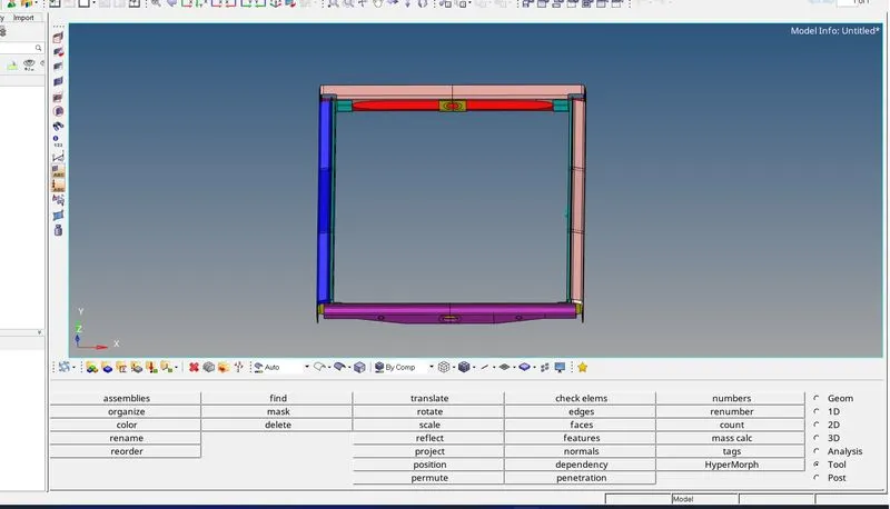
To generate a shell mesh over each component:
-
- 2D - automesh - surfs (displayed) - target length =5 - specify elem type and order - mesh
- However to achieve a perfect mesh without quality errors the comp is sectioned into different surfaces using surf trim option and meshed separately.
- Since volume tetras arent being generated, the surfaces can be meshed with quads majority
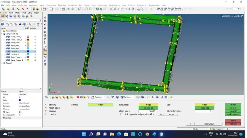
- Similarly, symmetrical components can also be trimmed about the mid point and meshed and reflected about the central axis
- Finally all components have been meshed using 2D elems (trias and quads)
Assigning property card
- A single property and material card is added for every component.
- Assuming every comp has the identical thickness and material, a single card is added to each
- To create a material card: name =steel - type=ISOTROPIC - card=MAT1
- Then the necessary material values like poissons ratio, youngs mod etc.. are specified
- Similarly a new property card is created with the PSHELL card image and the above mat card is assigned to it.
- The thickness of the comp are also specified in the property card.
- Each card is assigned the property card which is linked to the material card.
1. Seam-Quad(angled+capped+L)
For: Right_Rail_2 & Front_truss_1
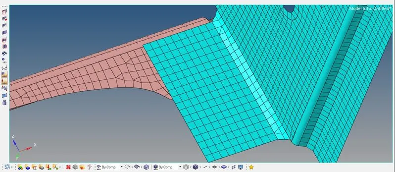
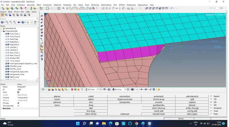
- To create a seam weld: Connectors - seam
- Select the nodes (by path) on one of the component
- tolerance = Specify the search distance (10mm)
- Select the two components and keep the imprint check on
- weld type is set as seam-quad (angled+capped+L)
- The weld angle can be altered but an angle of 60 or 45 is widely preferred based on the alignment of the two components.
- The spacing is set a 5mm. Spacing defines the distance between the two adjacent weld elements
2. Seam- Quad elements
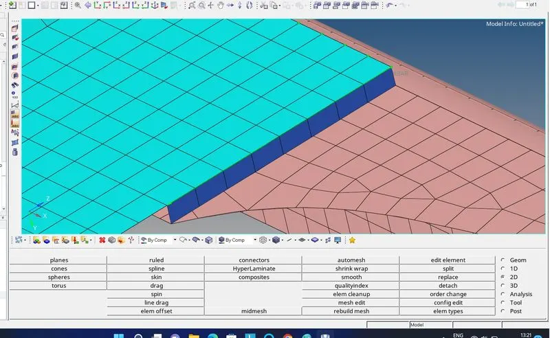
For: Left_Rail_2 & Front_truss_1
- To create a seam weld: Connectors - seam
- Select the nodes (by path) on one of the components
- tolerance = Specify the search distance (10mm)
- Select the two components and keep the imprint check on
- weld type is set as quad and the spacing (distance between the two adjacent weld elements) is kept as 5mm
. Spot weld with 2 Layers and 5 mm Diameter
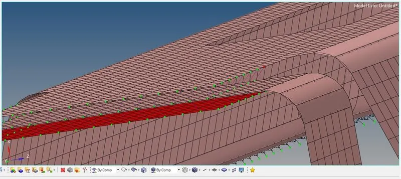
Front_truss_2, Front_truss_1 & Right_Rail_1
- To create a spot weld: 2D - connectors - spot - type=weld
- Select all the required nodes where the location of the spot weld has to be placed.
- Then select all the 3 components
- Specify a diameter of 5mm and number of layers as 2.
- NOTE: Since the layer is set as 3, a minimum of three components have to be selected and in case only two components are present then the layer has to be set as 2.
4. Hexa (Adhesive)
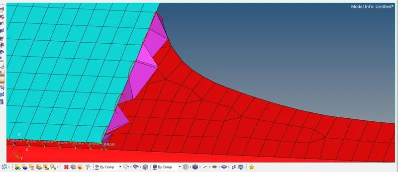
For: Front_truss_2, Front_truss_1 & Left_Rail_1
- To create a seam weld: Connectors - seam
- Select the nodes (by path) on one of the component
- tolerance = Specify the search distance (10mm)
- Select the two components and keep the imprint check on
- weld type is set as hexa (adhesive) under the weld type category.
- The strips and coats of the weld can be altered. In this case, the strip is set as 2 and a single coating is specified
5. Bolt Connector
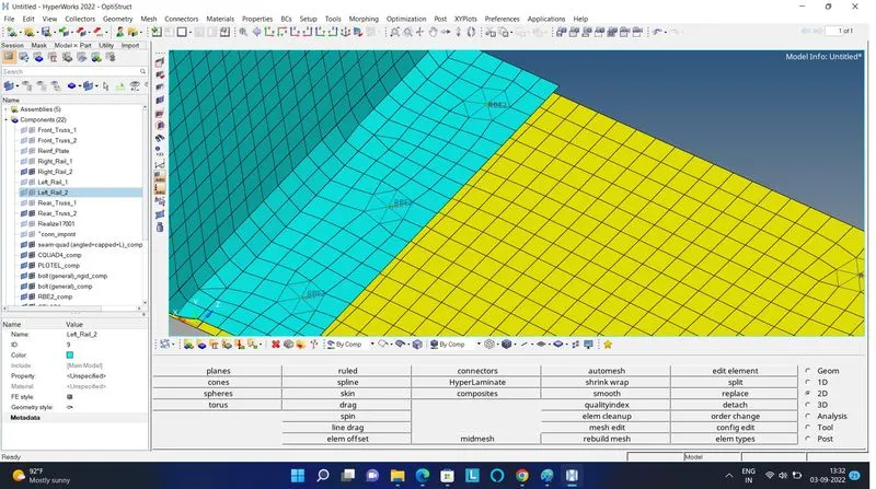
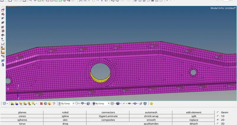
For: Rear_truss_2 & Right_Rail_2
- To create a bolt connector: Connectors - bolt
- Specify the location of the bolt by selecting two single nodes at a certain distance in one of the component since two bolt connectors are being realised.
- Select the two components which has to be fixed by the bolt.
- Select the option to create a hole to define the bolt as a physical element (Note that this will modify and alter the neighbouring mesh )
- Specify the search length (about 10mm)
The realised bolt connection is shown below
For: Rear_truss_2 & Left_Rail_2
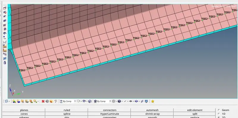
7. Spot-weld with Rigid Elements
For: Right_Rail_1 & Right_Rail_2
- As similar to previous spot weld creation, this spot weld is created using rigids instead of weld
- To create a spot weld: 2D - connectors - spot - type=rigids
- Select all the required nodes where the location of the spot weld has to be placed. (by path)
- Then select all the 2 components
- Specify the diameter and number of layers as 2 (since only two components are present)
Spot-weld with Spring Elements
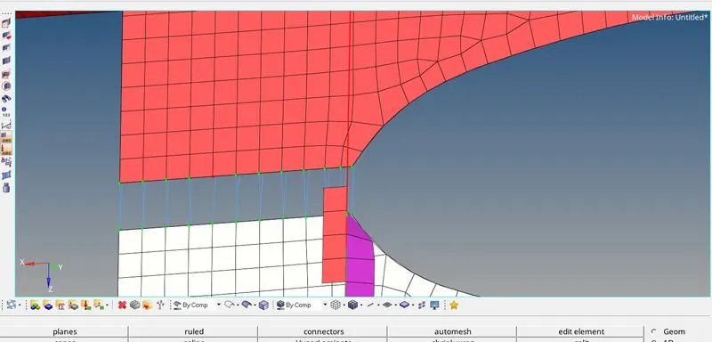
For: Left_Rail_1 & Left_Rail_2
- Similarly as done for the previous case, here the spot element type is set as spring instead of rigid or weld
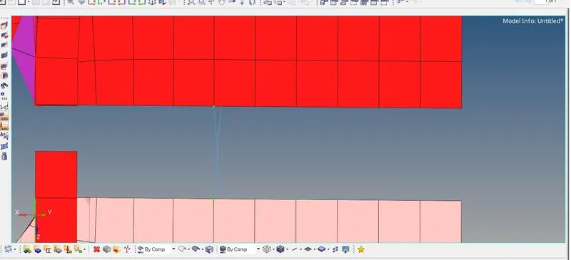
9. For other components
- In case of the shell component with the hole, a adhesive connection is made.
- Adhesives are RBE3 elements that distribute load applied to its master node. Unlike RBE2 elements, RBE3's do not impart infinite stiffness to the component.
- To create adhesives using area connector method:
- 2D - connectors - area - type=adhesive - select elems and components - (optional) specify coat layer - specify search tolerance - create
- Similarly, a seam weld is created on other components.
- A seam weld with a (vertical+angled) type is created as shown below:
- 2D - connectors - seam - type=seam-quad(vertical+angled)
- Then specify the weld angle as 45 degree and slected required elems and components.
- The realized connection is shown below
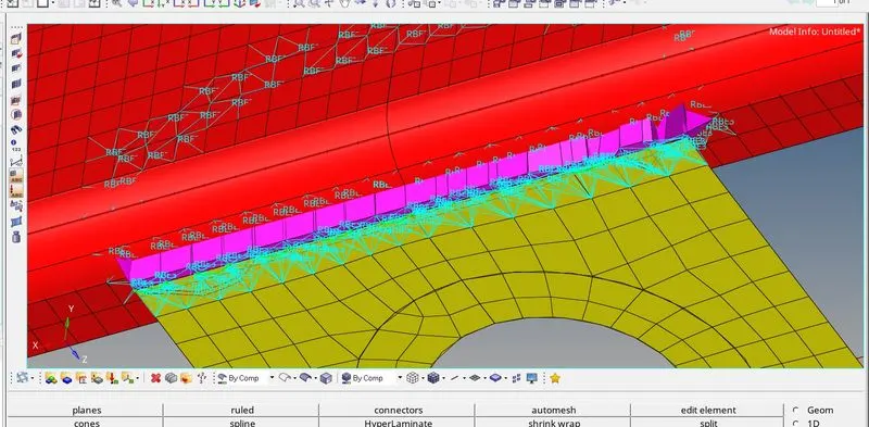
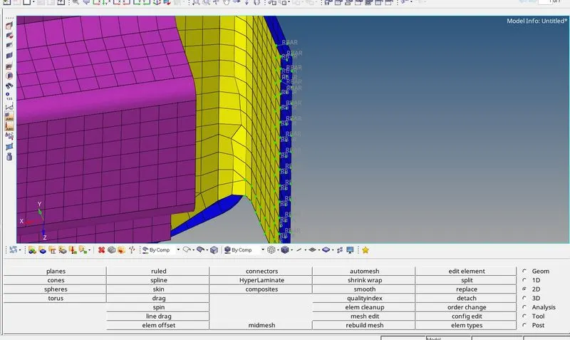
NOTE: To visualize the shell components along with their thickness specified in their property card, select '2D detailed elemental representation'
CONCLUSION:
Hence every components have been meshed and required connections have be defined and sucessfully realized.
Finally the entire connections and meshed components are shown below