Creation of 1D Connectors
Creation of 1D Connector's Challenge.
Objective -
- To mesh the given frame assembly with 2D elements with a target element size of 5 units.
- Use different types of Connection techniques and Deploy connectors to the components as given below.
- How to debug the connector's, If they are failing.
- Right_Rail_2 & Front_truss_1 - Seam-Quad(angled+capped+L).
- Left_Rail_2 & Front_truss_1 - Quad elements.
- Front_truss_2, Front_truss_1 & Right_Rail_1 - Spot weld with 2 Layers and 5 mm Diameter.
- Front_truss_2, Front_truss_1 & Left_Rail_1 - Hexa (Adhesive).
- Rear_truss_2 & Right_Rail_2 - Bolt Connector.
- Rear_truss_2 & Left_Rail_2 - Bolt Connector.
- Right_Rail_1 & Right_Rail_2 - Spot-weld with Rigid Elements.
- Left_Rail_1 & Left_Rail_2 - Spot-weld with Spring Elements.
- The component's which have been left, Join them all with suitable connectors.
Theory of Connector's and their terminologies -
Connectors Definition :
- They are geometric entities (not FE) primarily used to create spot- and seam welds, but also used to create adhesives, bolts and masses.
- They are simply a database of information defining specific requests for connections at specific locations.
- They are a medium to create both solvers independent and/or solver dependent connections between geometric and/or FE entities.
- They can be created interactively or from different master connection files (.xml, .mcf, .vip).
Types of Connectors:
Spot-
- Connections at a point.
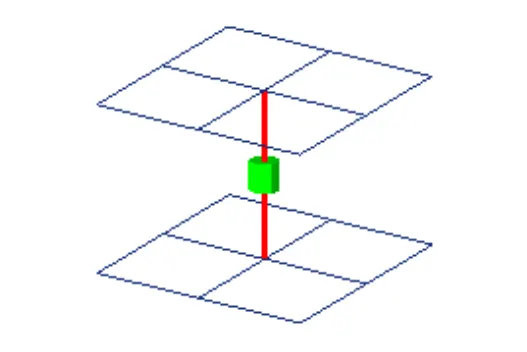
| Figure 1-Spot |
Bolt-
- Connections at hole locations.
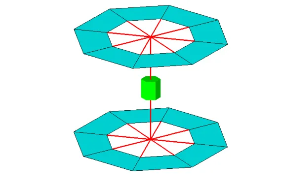
| Figure 2-Bolt |
Trim Mass-
- Non-physical mass.
- Simplification through replacement of parts with mass only or add mass to the existing part.
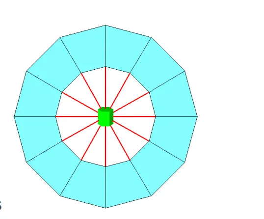
| Figure 3-Trim Mass |
Seam-
- Connections along a length.
- Seam welds.
- Connects geometry only.

| Figure 4-Seam |
Area-
- Connection of areas.
- Adhesives.
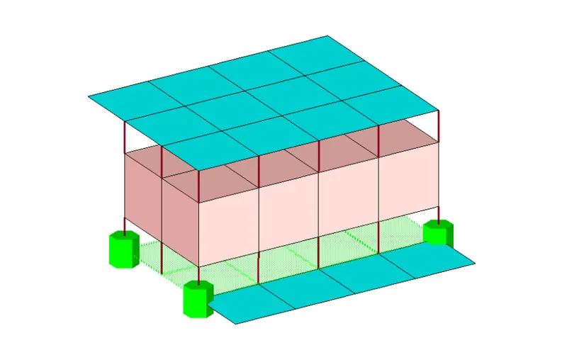
| Figure 5-Area |
Connector's Module-

| Figure 6-Connector's Module |
- Spot
- Bolt
- Seam
- Area
[create, edit, and realize that style of connectors.]
- Apply Mass – adds a mass value to entities. Used to represent the mass of parts that are not present in the model.
- FE Absorb – Create new connectors from existing elements of recognizable FE representations of welds, bolts, adhesives, etc.
- Add Links – Add link entities to existing connectors.
- Unrealize – Delete FE representations of welds/bolts/adhesives associated with existing connectors.
- Compare – Checks the MCF against the displayed model file.
- Quality – Check for duplicate connectors, combine connectors, check the quality of realized elements.
Connectors-Terminology
Link Entities - The entities that are being connected.
- Users can explicitly define link entities or specify a search tolerance.
- Can be components, elements, surfaces, nodes, or tags.
- Typically components are linked.
Connector Location - Where the entities are linked.
- Nodes – created at the node location.
- Points – created at the point location.
- Lines – created for the line may be split into multiple projection locations as specified by the offset, spacing, and density values.
- Elements – created at the element location (adhesives only).
- Surface – created at the surface location (adhesives only).
Connector Realization – The creation of the finite element representation of that connector.
- Rigids, springs, etc., or custom configurations such as ACMs, CWELDS, etc.
Three Types of Connector's State – Whether an FE representation of a connector has been created.
- Unrealized - The initial status of the connector entity upon creation.
- Newly created or imported connector before the first realization.
- Editing the connector definition (i.e. add or delete a link entity from the connector), the connector removes the welds it created and reverts back to an unrealized state.
- Manual unrealization.
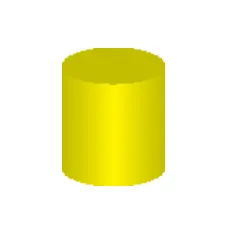
| Figure 7-Unrealized |
- Realized - The status only if the creation of the FE weld representation at the connector was successful.
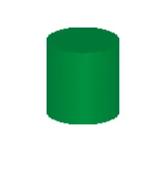
| Figure 8-Successfully Realized |
- Failed – The status of creating the FE weld representation at the connector was not successful(Failed).
- If the creation of the FE representation is unsuccessful (due to low tolerance, insufficient link entities, etc.) the connector icon is displayed as failed (red).
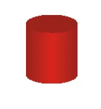
| Figure 9-Failed Connector |
Layer's
- The number of FE weld layers to attempt to generate for the connector 2T, 3T, etc.
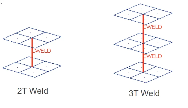
| Figure 10-2T,3T Weld |
Link's to some useful articles about connector's
- https://documentcloud.adobe.com/link/track?uri=urn:aaid:scds:US:1c7d2c33-6b24-4c77-96c4-09fa07b978fc
- https://documentcloud.adobe.com/link/track?uri=urn:aaid:scds:US:fc3ff7dc-2ac2-40fc-bd72-1d6beb4d0382
- https://skill-lync.com/knowledgebase/realizing-connectors
These are the Connection's which are used mostly in industries-
- Seam Weld
- SpotWeld and
- Bolt Weld
Seam Welding and its Applications-
- Seam welding is the joining of workpieces made of similar or dissimilar materials along a continuous seam. Seam welding can be broken down into two main techniques, resistance seam welding and friction seam welding.
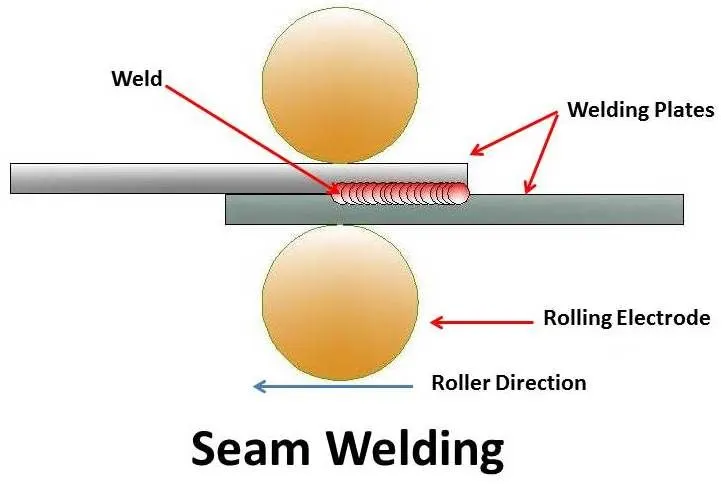
| Figure 11-Seam Weld |
- It is used for welding stainless steel, steels alloys, nickel and its alloys, magnesium alloys etc
Spot Welding and its Applications-
- Spot welding (or resistance spot welding) is a type of electric resistance welding used to weld various sheet metal products, through a process in which contacting metal surface points are joined by the heat obtained from resistance to electric current.
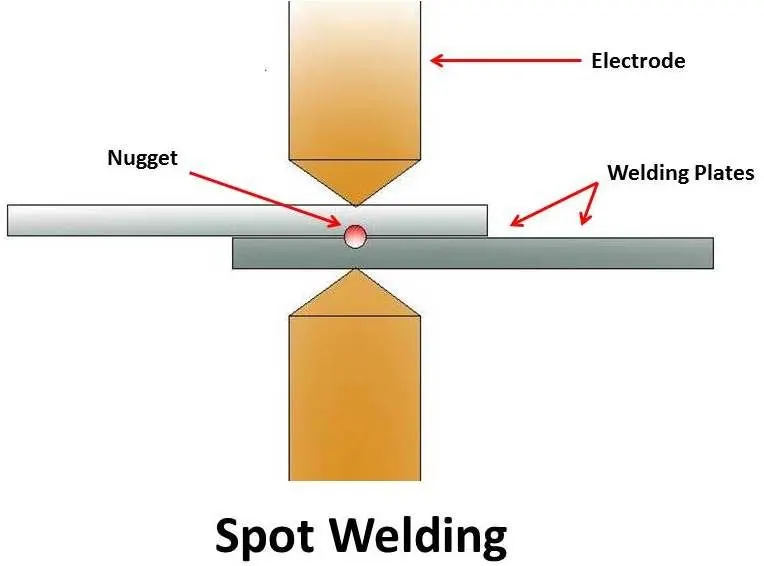
| Figure 12-Spot Weld |
- Spot welding is typically used when welding particular types of sheet metal, welded wire mesh or wire mesh.
Bolt Connection's Model-
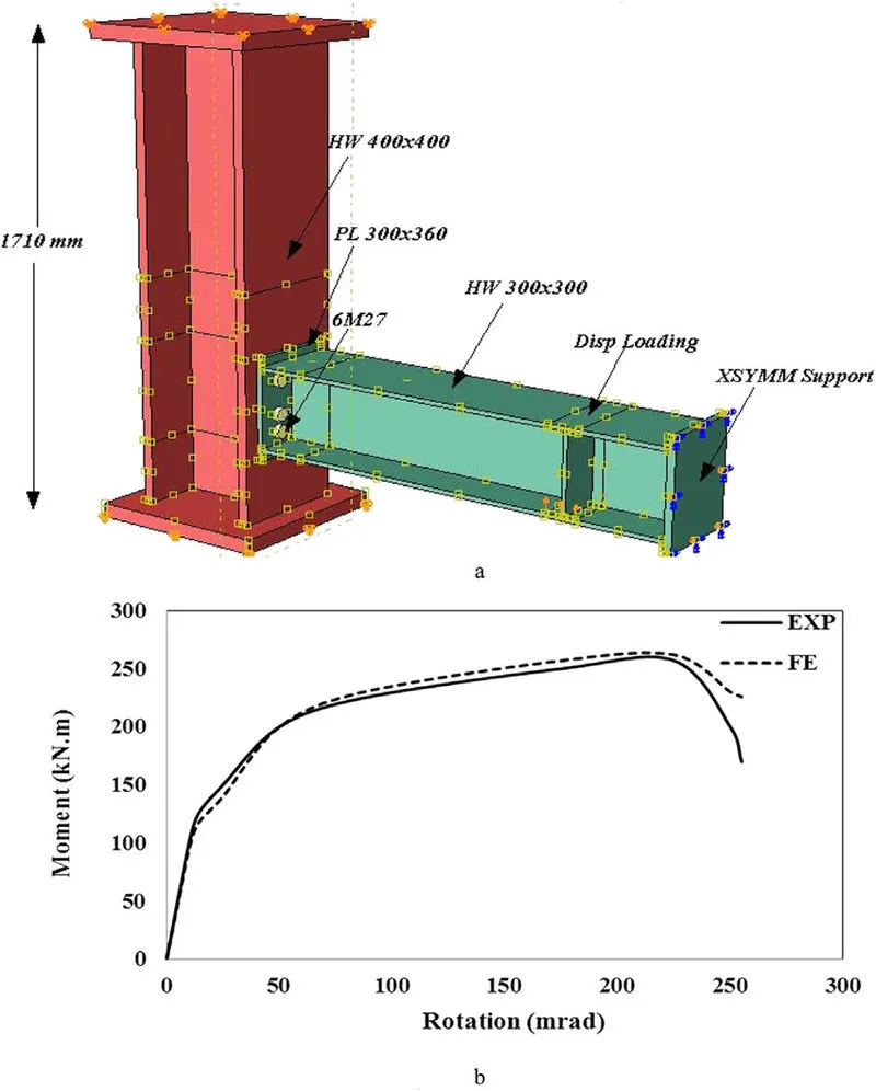
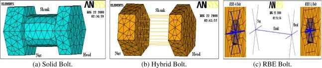
| Figure 13-Bolt Connection's |
Procedure -
- Deploying connector's in the sense, A type of joining operation which is used to combine the different components of an assembly.
Phase 1:Importing the Model
- First, import the model to the user interface from the file given to us.
- Hence we are importing a given CAD geometry into hypermesh.
- There are file formats like IGES, STEP, Parasolid where we can import these file formats into any CAD, CAE Softwares.
- But in hypermesh we can only import three file formats like
- IGES [Initial Graphics Exchange Specification].
- STEP [Standard for the Exchange of Product Model Data].
- Solidworks.
- IGES, STEP, These two are standard file formats that are used most in industries. But nowadays in industries, they are also using Parasolid file format.
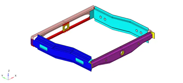
| Figure 14-Frame Assembly |
- After importing the model, Give the quality criteria parameter's to mesh the model which has been given below.
Target Element Size-5 Units
| S.N | Quality Criteria | Value |
| 1 | Aspect Ratio | 5 |
| 2 | Skewness | 45 |
| 3 | Warping | 15 |
| 4 | Taper | 0.5 |
| 5 | Min. Length | 2 Units |
| 6 | Max. Length | 8 Units |
| 7 | Min angle Quad | 45 |
| 8 | Max angle Quad | 135 |
| 9 | Min angle Tria | 30 |
| 10 | Max angle Tria | 110 |
| 11 | Tria % | 15 |
- Follow the quality criteria given above and mesh the component with a target element size of 5 units.
Phase 2-Examining
- Before working on the model. We have to check the geometry if there are any errors like
- Damaged Geometry.
- Free edges in unnecessary areas.
- Unnecessary points on the lines.
- Unnecessary Connections and connectivity errors.
[Note: If you want you can check all these for this given model, But in this challenge, no need to do that, Focus on the connectors. But for the other model's, you will be checking all these and then only you will deploy a connector]
2:1 Assigning a property and Material for the components.
- To assign a property, Right-click on the feature tree panel/right-click⇒">⇒⇒create⇒">⇒⇒property.
- Do the same thing for the material also.
- After creating property and material. Select the property and give the material which you have created and thickness to the property.
- And then go and assign the property to the component from which you have extracted the mid surface.
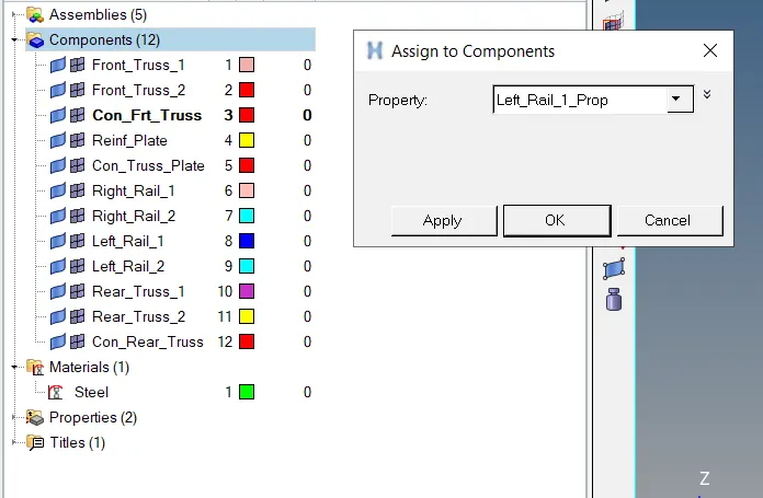
| Figure 15-Assigning Property for the Component's |
2:2 Checking symmetry for the components.
- By examining the components, we have only 4 components which are symmetric called
- Right Rail 1
- Right Rail 2
- Left Rail 1
- Left Rail 2
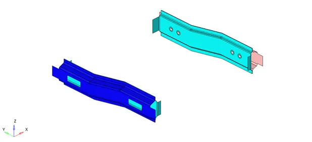
| Figure 16-Symmetric Component's |
2:3 Why checking symmetry is necessary for the components?
- Cause we can save time.
- If we have symmetry in the components. We can cut it into half and we can reflect the surface and mesh on the other side. By doing this, we can save a lot of time instead of doing both sides.
- For this Component, No need to cut the surface, Just we will be reflecting elements and connectors to the other side.
[Note: For this component. You can reflect the connector's if you want. I'm describing below, Like how to reflect the connectors]
2:4 Manual Clean Up
- Manual clean up is necessary to achieve things like
- Proper mesh flow.
- Feature capturing.
- To eschew the elements failing for the minimum length.
- For surface deformations.
- For connectivity errors.
[Note: Proper Mesh Flow is important for the connector's, Then only you can deploy a connector successfully, If your mesh is not proper then you can't deploy a connector or the connector will fail. So be aware of it.]
Phase 3-Start Meshing
- You can mesh the component's individually or you can mesh it entire assembly at a time.
- As of now for this challenge, We will be only focussing on connector's, So mesh the entire assembly.
- You can give mesh types as quads, mixed,trias. It's up to you.
- Now I'm meshing this component and using mesh types as quads.
- Open the AutoMesh panel by pressing F12.
- Go to the size and bias subpanel.
- Set the mesh mode to automatic. (It may currently be set to interactive.)
- Set the entity selector to surfs.
- Click surfs >> displayed.
- In the elem size = field, enter 5.
- Set the mesh type to the quad.
- Set the elements to surf comp/elements to current comp toggle to elements to surf comp.
- Click mesh. HyperMesh meshes the surfaces.
- Click return.
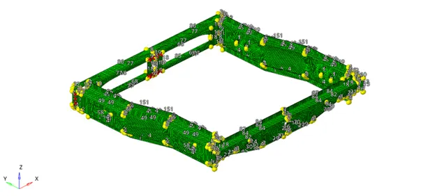
| Figure 17-Meshing Component |

| Figure 17-Mesh Panel |
[Note: As of now for this challenge, No need to check element quality. We will be focussing on connector's only]
Phase 4-Start Giving Connection's to the Component's
- Before giving connection's to the components, Load the connector browser from the user interface panel.
- Open the Connectors browser by
- By clicking View > Browsers > HyperMesh > Connector from the menu bar.
- Review the layout of the Connector browser. Currently, there are no components or connectors listed because there are no connectors in the model.
- [Note: Use the Connector browser to view and manage connectors.
- The top portion of the browser is referred to as the Link Entity browser, and it displays information about linked entities.
- The middle portion is referred to as the Connector Entity browser, and it contains a list of the connectors in your model.
- The bottom portion of the browser is referred to as the Connector Entity Editor, and it displays attributes assigned to the connector(s) selected in the Connector Entity browser. HyperMesh groups the connectors based on their connection type.
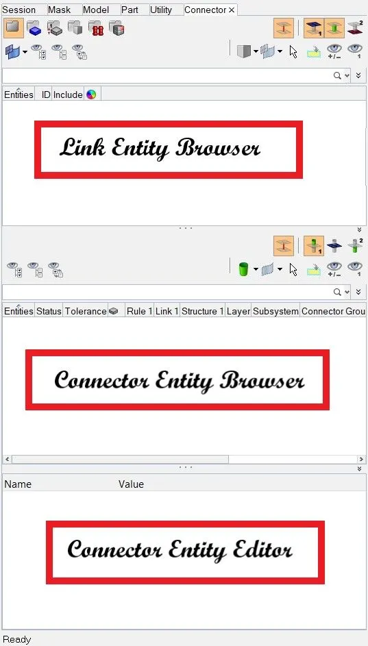
| Figure 18-Connector Browser |
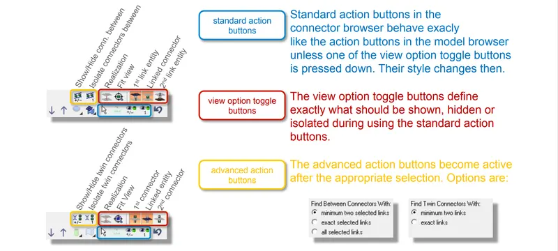
| Figure 18:1 Connector Browser |
- Right Rail_2 & Front Truss_1-
- Create connectors between the shell mesh of the Right_Rail_2 and Front Truss_1.
- Seam Panel Organization

| Figure 18:2 Seam Panel |
- Seam Subpanel-Create and realize seam connectors.
- Create Subpanel-Create, but do not realize seam connectors.
- Realize Subpanel-Realize existing seam connectors (no creation or editing possible).
- Edit Subpanel-Edit existing seam connectors.
- Partition Subpanel-Partition (separate into sections of connections that passed or failed valid projections) an existing seam connector.
- In the Model Browser, Component folder, right-click on the Right_Rail 2 and select Make Current from the context menu and isolate that component.
- Open the Seam Panel.
- Go to the Seam subpanel.
- Set the location selector to node list.
- Click node list >> by path
- Set the connect what selector to comps and click comps.
- Select the components-Right_Rail_2 and Front Truss_1.
- Change Weld type to Seam-Quad(angled+capped+L).
- Give proper Spacing, Search Tolerance, Weld Angle, Cap Angle, Runoff Angle.
A Brief Explanation about Spacing, Search Tolerance, Weld Angle, Cap Angle, Runoff Angle.
Spacing-
Distance between each weld location on the line.
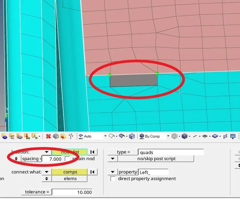
| Figure 19-Before |
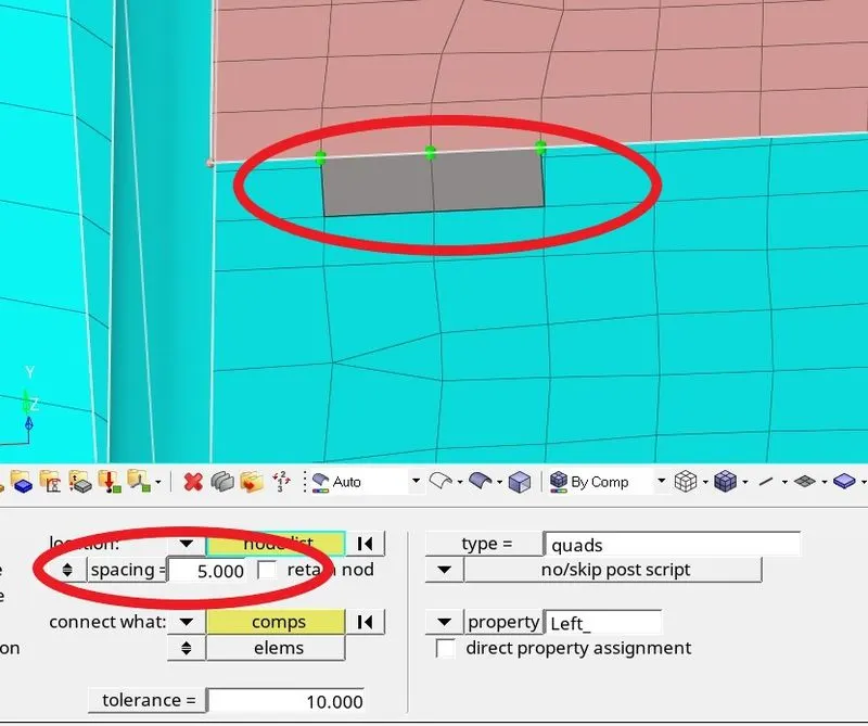
| Figure 20-After |
- In this figure 19 and 20, You can see the difference. You might get an idea, What is spacing.
- [Note: Alway's give a spacing value as your target element size given.]
Search Tolerance-
- Define a distance from the connector location (per each test point).
- Only entities within this tolerance can be taken into account for the link detection and the final realization. Thus, the tolerance is used twice: first for the link determination and again for the realization. In the second step, the tolerance is used to verify whether adequate link candidates are available to be connected.
- During pure connector creation on the Create subpanel, the tolerance is used for the link determination, but not necessarily stored on the connector unless the checkbox in front of the tolerance field is marked. In this way, different tolerances can be used.
- The tolerance used during the realization process is always written to the connector.
Weld Angle-
- Define the distance between the normal projection and the quad direction.
- Principally it is allowed to define weld angles between 0 and 90 degrees. If the value is set to 0 an internal thickness-based calculation is used. If the value is set to 0 and no thickness is defined the connector will fail.
- If the angle is created in the wrong direction, the seam can be reverted by enabling the reverse direction checkbox and performing a realization.
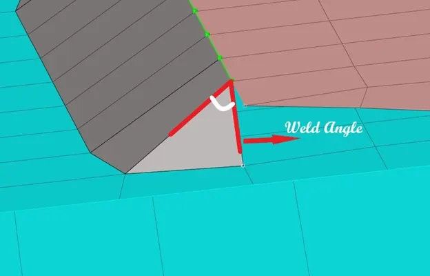
| Figure 21-Weld Angle |
Cap Angle-
Depending on the seam-quad type, the cap angle is measured differently.
- Measured between the normals of the cap element and the second-to-last element of the seam.
- Measured between the edge normals of the cap element and the second-to-last element of the seam in the plane of the opposite link.
- Cap angles are created by default. Clear this checkbox to remove cap angles and runoff angles.
- Cap angles between 0 and 45 degrees are permitted, but be aware that larger values can lead to bad elements. The recommended value is 10 or smaller. Cap angles between 45 and 90 degrees are permitted, but be aware that smaller values lead to bad elements. The recommended value is 75 degrees and higher.
[Note:Only available for seam-quad (angled + capped + L) and seam-quad (angled + capped + T)]
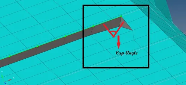
| Figure 22-Cap Angle |
Runoff Angle-
Depending on the seam-quad type, the runoff angle is measured differently.
- Measured between the normals of the last and the second-to-last last element of the seam.
- Measured between the edge normals of the last and the second-to-last element of the seam in the plane of the opposite link.
- It is recommended to define the runoff angle between 0 to 10 degrees.
Clearing the cap angles checkbox removes runoff angles, which are created by default.
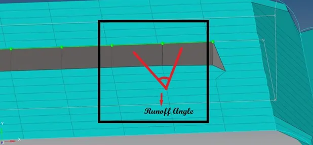
| Figure 23-Runoff Angle |
Retain Nodes-
- Retain the position of the nodes when you create and realize a connector.
- To create a seam weld Go to seam weld panel >> Location >> Nodepath >> Connect What:Select the Component's called Front Truss_1 & Right Rail_2 >> Type:Seam-Quad(angled+capped+L) >> Create.
- Give the Property what you assigned to the component's and give the required values for the cap angle, runoff angle, weld angle.
- Give the required value for the search tolerance. We will be giving a tolerance value of 10. This value is like a default value. This value is enough to give for this component. If there is a long space between the component's, then you have to give a higher tolerance value or you have to be translating the component If the connectors are not realizing or failing.
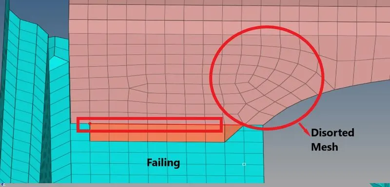
| Figure 24-Connector Failed |
When the connector is failing or not realizing, Remesh or rebuild mesh that region. Then the connector won't fail. Make sure whether you are giving a proper search tolerance and spacing.
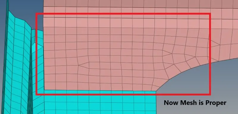
| Figure 25-After Remeshing.Now mesh is a little bit proper. Now deploy a Connector. |
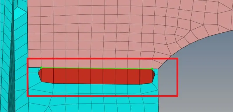
| Figure 26-Realized Connector |
- Now after remeshing or after rebuilding the mesh, The connector is not failing and it is realized.
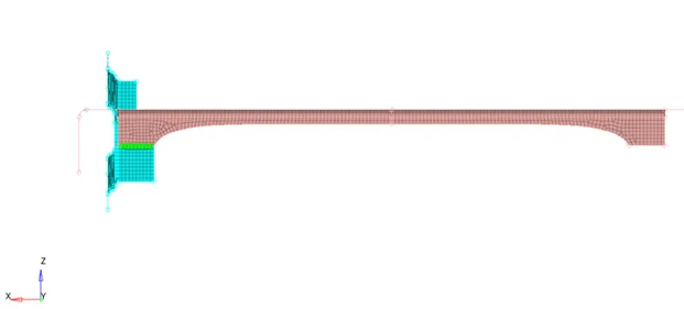
| Figure 27-Connector has been Deployed |
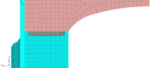
| Figure 28:Deployed Connector |
2. Left_Rail_2 & Front_Truss_1-
- Similarly what you did for the previous model. Do the same thing for this component also. Just change the realization type, that's it.
- The realization type is a description of the FE representation.
- To create a seam weld,Go to seam weld panel >> Location >> Nodepath >> Connect What:Select the Component's called Front Truss_1 & Right Rail_2 >> Type:Quads >> Create.
Mesh adjustment method-
- Quad transition-Create quads to serve as a transition.
- Remesh-Remesh linked entities to achieve better links.
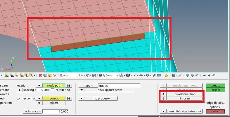
| Figure 29-With Quad Transition and Imprint |
- Imprint-Merge two meshes from two different link entities to create a transition mesh that matches up well with both.
- Skip imprint-Close-set connectors' transition quads may overlap and interfere with each other, causing one or more realizations to fail.
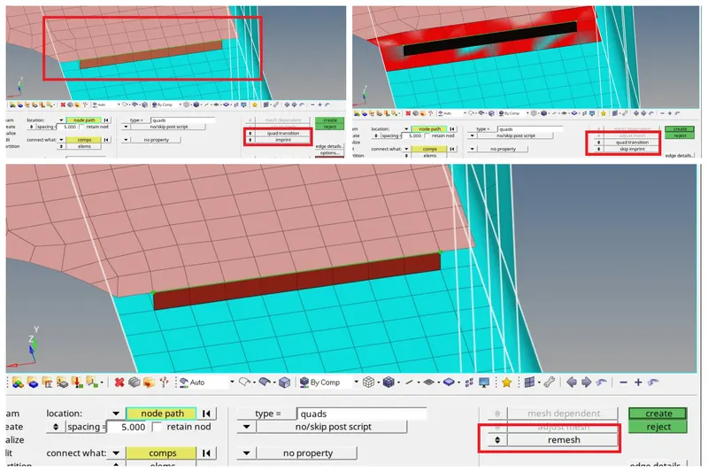
| Figure 30-With Quad Transition and Imprint, With Quad Transition and Skip Imprintand With Remesh |
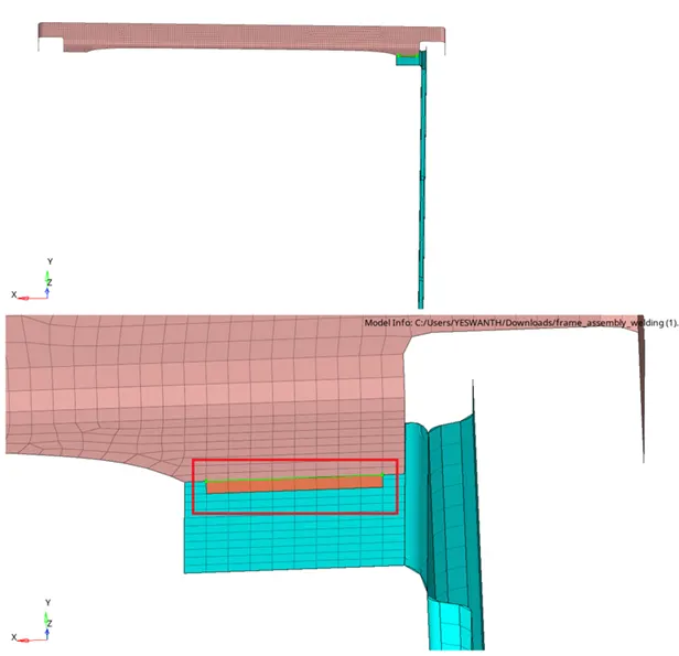
| Figure 31-Deployed Connector in Left_Rail_2 & Front_Tuss_1 |
3.Front_truss_2, Front_truss_1 & Right_Rail_1-
- I'm doing spot weld for this component. I'm using realization type
- Spot welding is primarily used for joining parts that are normally up to 3 mm in thickness. The thickness of the parts to be welded should be equal or the ratio of thickness should be less than 3:1. The strength of the joint depends on the number and size of the welds. Spot-weld diameters range from 3 mm to 12.5 mm.
- Spot welding can be easily identified on many sheet metal goods, such as metal buckets. Aluminium alloys can be spot welded, but their much higher thermal conductivity and electrical conductivity requires higher welding currents.
- Spot Subpanel-Create and realize spot connectors.
- Create Subpanel-Create, but do not realize spot connectors.
- Realize Subpanel-Realize an existing spot connector (no creation or editing is possible).
- Edit Subpanel-Edit an existing spot connector.

| Figure 32-Spot Sub Panel |
Mesh Dependent / Mesh Independent-
- Determine whether the realizations require a node connection.
- Mesh independent-For a realization which does not need any node connection and the connection is primarily defined via a solver-specific card or the nodes which need to be connected are defined by just a cylinder.
- Mesh dependent-All other cases.
Adjust realization / Adjust mesh-
- Adjust realization-Adjust the realization itself, such as allowing non-normal realizations for the sake of locating nodes to create the realization.
- Adjust mesh-Adjust the mesh should locally (such as creating transition elements or remeshing) to ensure proper realization.
- Go to spot sub panel >> location >> nodes list >> by path >> connect what:components >> type:sealing >> dia:5 >> create.
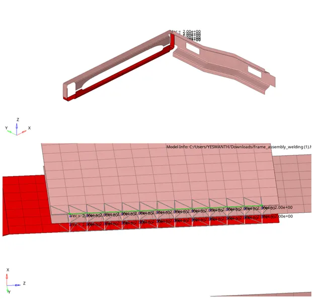
| Figure 33-Realized SpotWeld with Realization Type-Sealing |
4. Front_truss_2, Front_truss_1 & Left_Rail_1-
- Similarly, For this component I'm doing seam weld but with realization type of Hexa(Adhesive).
- Hexa adhesives are used for the component's which are used to join them with industrial adhesives.
- Adhesives are mostly used in fastening applications.
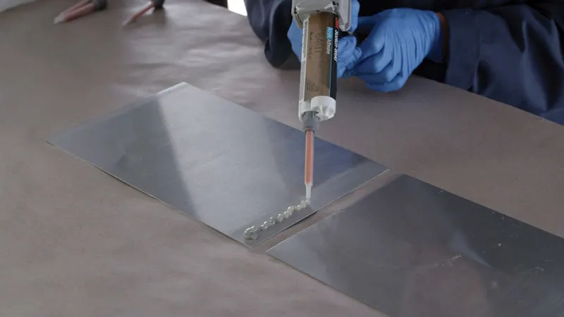
| Figure 34-Industrial Adhesive |
- Go to Seam Weld sub panel >> location >> nodes list >> by path >> connect what:components >> type:hexa adhesive >> hexa position >> midpoint/positive edge/negative edge/offset from edge >> create.
- Give a suitable search tolerance, strips, coat's, width to get the connector realized.

| Figure 35-Seam Sub Panel |
- Width-Define the width of the continuous Hexa weld in the direction perpendicular to the seam direction.
- Strips-Define the number of Hexa elements required along the width.
- Coats-Defines the number of Hexa elements required along with the thickness.
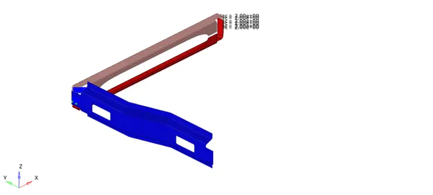
| Figure 36-Deployed Seam Connector |
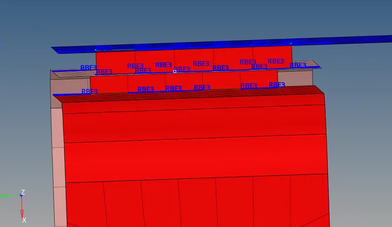
| Figure 37-Realized Connector with Hexa Adhesive type |
5.Rear_truss_2 & Right_Rail_2-
- For this component, I will be giving a bolt connection.
- A bolt is a metal pin with a head formed at one end and the shank threaded at the other end so that nut can be received. Generally, the bolts are used to connect the pieces of metals by inserting them through the holes in the metals; at the threaded end, nuts should be tightened.
- Bolt Subpanel-Create and realize bolt connectors.
- Create Subpanel-Create, but do not realize bolt connectors.
- Realize Subpanel-Realize existing bolt connectors (no creation or editing possible).
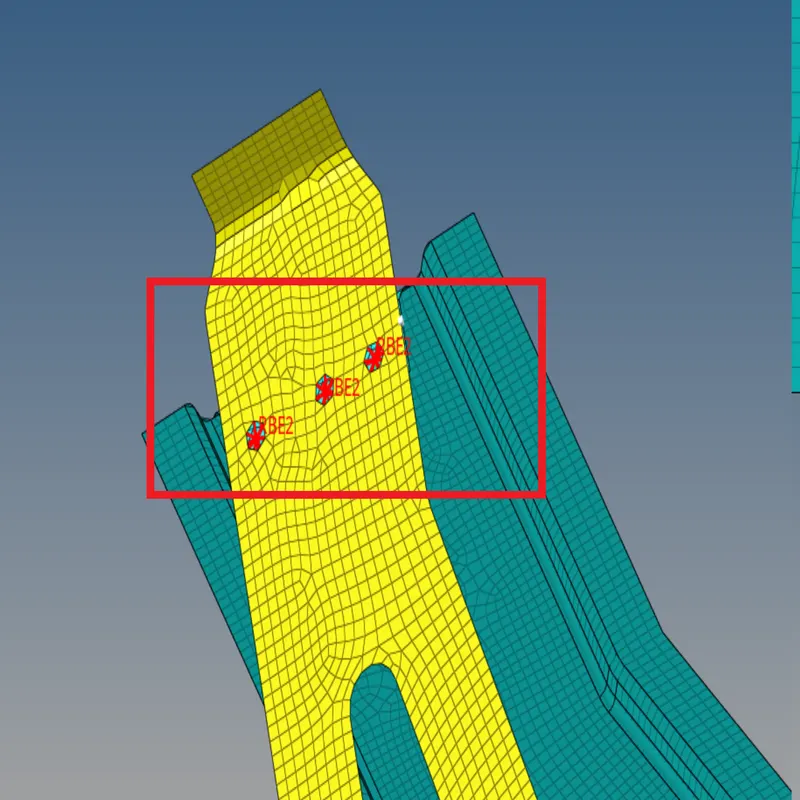
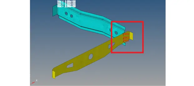
- Now go to the bolt sub panel and create a bolt connector between the meshed component's.

| Figure 38-Bolt Subpanel |
- Bolt subpanel >> location >> nodes list >> connect what:components >> type:bolt (spider)>> create.
- If there is consider existing hole only in the mesh dependent drop-down menu, The component should also have holes, If not change it to the if none create holes. Then the connector will be realized, It won't fail.
- Consider existing holes only/create a hole, if none/use hole, if available/fill and remesh hole, if available-
- In the past, a bolt realization always required a hole for each layer existent in the initial mesh. For 2D meshes, this is not necessary anymore, because the imprinting capability allows punching the needed holes into the mesh before the final realization is performed, so the mesh can be manipulated in a pre-step. This makes it possible to punch holes, to move holes, to close holes, to create washers, and so on.
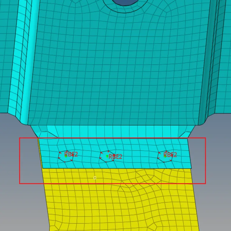
| Figure 39-Bolt Connector With Realization Type Bolt(Spider) |
| Figure 39:1-Bolt Connector With Realization Type Bolt(Spider) |
| Figure 40-Deployed Bolt Connector |
6. Rear_truss_2 & Left_Rail_2-
- Similarly, do the same thing for this component also what you do in the previous component.
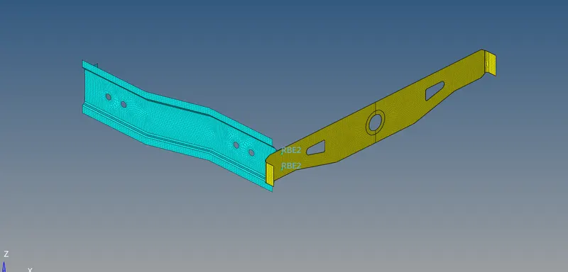
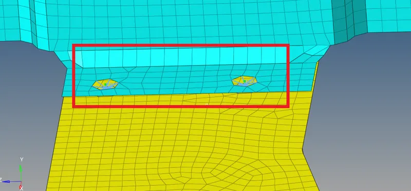
- Here I'm changing the realization type to clip and then deploying a connector.
- Bolt subpanel >> location >> nodes list >> connect what:components >> type:bolt (spider)>> create.

| Figure 41-Bolt Connector Sub Panel |
- If there is consider existing hole only in the mesh dependent drop-down menu, The component should also have holes, If not change it to the if none create holes. Then the connector will be realized, It won't fail.
- Consider existing holes only/create a hole, if none/use hole, if available/fill and remesh hole, if available-
- In the past, a bolt realization always required a hole for each layer existent in the initial mesh. For 2D meshes, this is not necessary anymore, because the imprinting capability allows punching the needed holes into the mesh before the final realization is performed, so the mesh can be manipulated in a pre-step. This makes it possible to punch holes, to move holes, to close holes, to create washers, and so on.
| Figure 42-Bolt Connector |
| Figure 43-Bolt Connector With Realization Type Clip |
7.Right_Rail_1 & Right_Rail_2-
- For this component, I'm deploying spot weld with realization type rigid element's.
- In the Model Browser, Component folder, right-click on Right_Rail_1 and isolate it and then show the Right_Rail_2 and start to deploy a connector between two meshed component's.
- Open the Spot panel.
- Go to the spot subpanel.
- Set the location selector to points.
- Click node list >> by path
- Set the connect what selector to comps.
- Click comps and select Right_Rail_1 and Right_Rail_2.
- Set the num layers to a total of 2 or set to auto.
- Give appropriate search tolerance, spacing value and diameter and then click create.
- The connector will be created and realized. If not try to realize it.

| Figure 44-Spot Sub Panel |
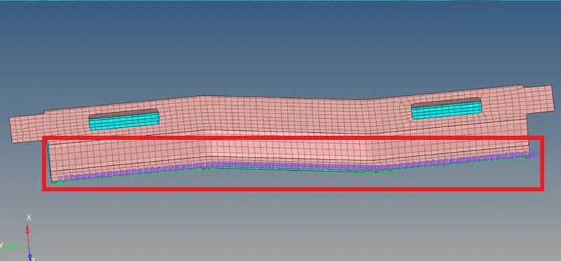
| Figure 45-Deployed Connector With Realization Type (Rigid Element's) |
8. Left_Rail_1 & Left_Rail_2-
- For this component, I'm deploying spot weld with realization type spring elements.
- In the Model Browser, Component folder, right-click on Right_Rail_1 and isolate it and then show the Right_Rail_2 and start to deploy a connector between two meshed component's.
- Open the Spot panel.
- Go to the spot subpanel.
- Set the location selector to points.
- Click node list >> by path
- Set the connect what selector to comps.
- Click comps and select Right_Rail_1 and Right_Rail_2.
- Set the num layers to a total of 2 or set to auto.
- Give appropriate search tolerance, spacing value and diameter and then click create.
- The connector will be created and realized. If not try to realize it.

| Figure 46-Spot Sub Panel |
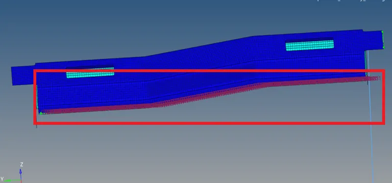
| Figure 45-Deployed Connector With Realization Type (Spring Elements) |
9. The component's which have been left without deploying a connector's-
- Here While Checking the model, Reinf Plate is not connected with the component's and check for the other component's also which have not been connected. If not deploy the connectors between them.
- Now start to deploy the connectors between the components.
- For one side. I'm deploying a seam weld connector with realization type seam-quad(angled+capped+L).

| Figure 46-Seam Sub Panel |
- In the Model Browser, Component folder, right-click on the Reinf_Plate and select Make Current from the context menu and isolate that component and show the Front_Truss_1 and Front_Truss_2 Component and start meshing the component and deploy a connector between the components.
- Open the Seam Panel.
- Go to the Seam subpanel.
- Set the location selector to node list.
- Click node list >> by path
- Set the connect what selector to comps and click comps.
- Select the components-Right_Rail_2 and Front Truss_1.
- Change Weld type to Seam-Quad(angled+capped+L).
- Give proper Spacing, Search Tolerance, Weld Angle, Cap Angle, Runoff Angle.
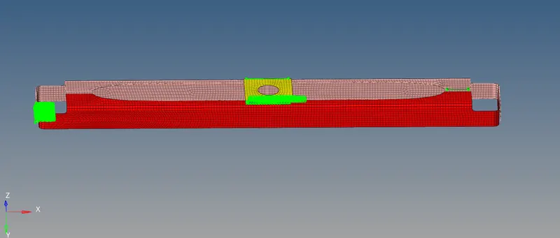
| Figure 47-Seam Connector |
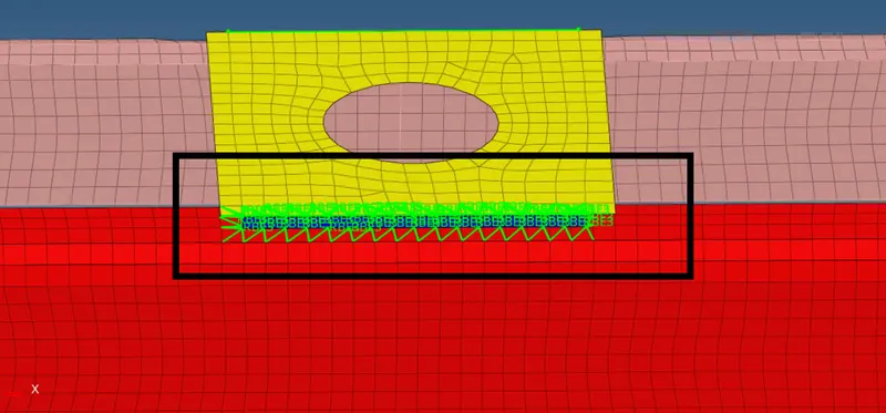
| Figure 48-Seam Connector With Realization Type Quad(angled+capped+L). |
- For the other side, I'm deploying a seamed connector with a realization type of Hexa(Adhesive).
- In the Model Browser, Component folder, right-click on the Reinf_Plate and select Make Current from the context menu and isolate that component and show the Front_Truss_1 and Front_Truss_2 Component and start meshing the component and deploy a connector between the components.
- Open the Seam Panel.
- Go to the Seam subpanel.
- Set the location selector to node list.
- Click node list >> by path
- Set the connect what selector to comps and click comps.
- Select the components-Right_Rail_2 and Front Truss_1.
- Change Weld type to Hexa(Adhesive).
- Give proper Spacing, Search Tolerance, Weld Angle, Cap Angle, Runoff Angle.
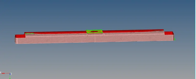
| Figure 49-Seam Connector With Realization Type of Hexa(Adhesive) |
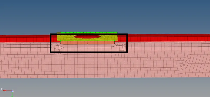
| Figure 50-Seam Connector With Realization Type of Hexa(Adhesive) |
Reflecting the Connectors -
- Here the symmetric component's are Right_Rail_1,Right_Rail_2 and Left_Rail_1,Left_Rail_2.
- First Mesh the component's Right_Rail_1,Right_Rail_2.
- And then if there is distorted mesh, Try to remesh or rebuild the mesh to get proper mesh flow, then only you can deploy a connector or it will fail.
- Then reflect the elements from Right_Rail_1,Right_Rail_2 to the Left_Rail_1,Left_Rail_2.
- You can deploy a connector, if the nodes are similar in both the component's or you can't deploy a connector, It may fail, So be aware of it.
- Now start to mesh the two component's Right_Rail_1, Right_Rail_2.
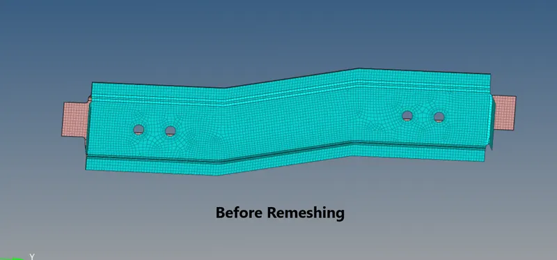
| Figure 51-Before Remeshing |
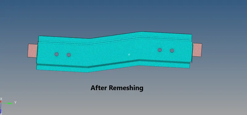
| Figure 52-After Remeshing |
- To reflect the element's from Right_Rail_1,Right_Rail_2 to the Left_Rail_1,Left_Rail_2 component's.
- Create a base node then only you can reflect the element's from Right_Rail_1,Right_Rail_2 to the Left_Rail_1,Left_Rail_2 component's.
- How to Create Base Node?
- Go to Geometry >> Nodes >> Arc Centre >> Select the lines of circle >> Create.
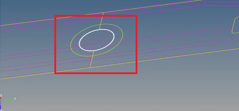
| Figure 53-Selecting the lines to create a node in the centre |
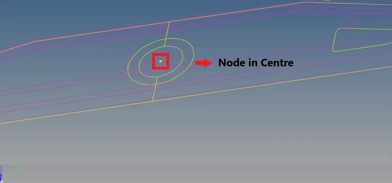
| Figure 54-Node Created in Centre of Circle |
- After Creating the nodes in the Reinf Plate circle and Rear_Truss_2 circle.
- Create the node in between the two circles of Reinf Plate and Rear_Truss_2 using interpolate nodes.

| Figure 55-Nodes Panel |
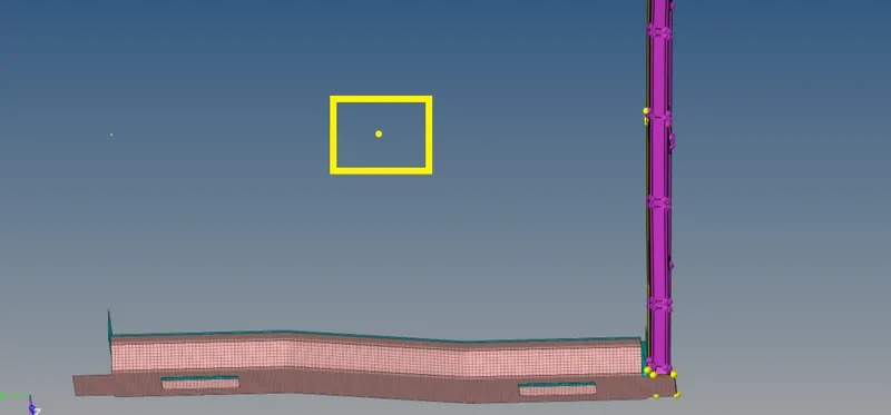
| Figure 56-Base Point Has Been Created |
- Now reflect the element's to the Left_Rail_1,Left_Rail_2 component's.
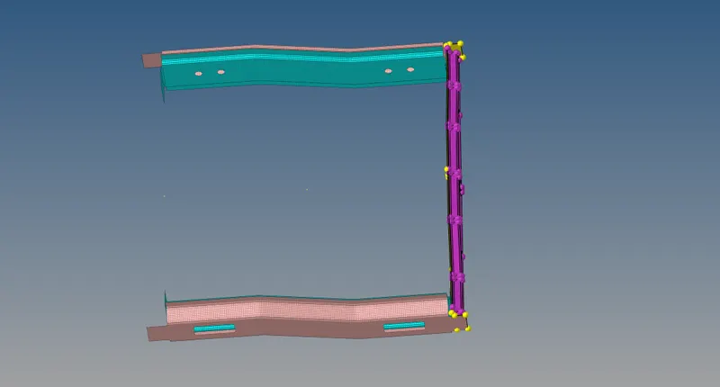
| Figure 57-Reflected Element's |
- Now only create the spot connector on the Right_Rail_1 component.
- Go to the spot connector panel and then go to the create panel which is only used to create a connector.
- Create a connector now by node list or node.
[Note: While creating the connector, Make sure whether you are checking the retain node box. If not tick the check box of retaining node, Then only you can realize a connector without failing or it will fail.]
- Spot >> location:nodelist >> by path >> connect what: select the component's Right_Rail_1,Right_Rail_2 >> create.

| Figure 58-Create Sub Panel |
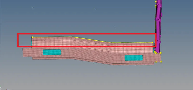
| Figure 59-Connector Created |
- Now reflect the connector to the Left_Rail_1.
- How to reflect a connector ?-Go to Tools >> reflect >> connectors >> select connector manually >> duplicate >> switch to x-axis >> select base node >> reflect.

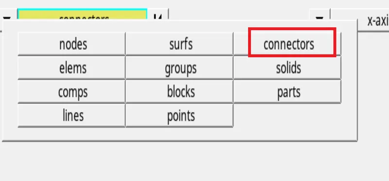
| Figure 60-Reflect Panel |
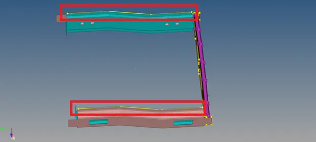
| Figure 61-Connector has been reflected |
- Now realize the connector on Right_Rail_1,Right_Rail_2 component's.
- And realize the connector on Left_Rail_1,Left_Rail_2 component's.
- How to realize a connector?
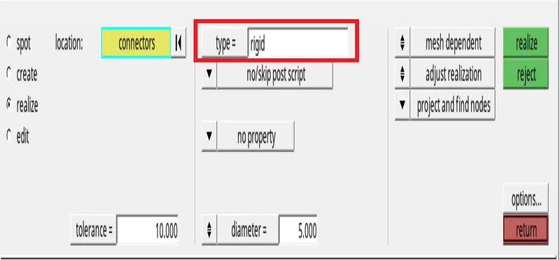
| Figure 62-Realize Sub Panel |
- Go to realize sub panel >> select a connector >> type:rigid >> give appropriate search tolerance,diameter >> realize.
- While realizing the connector on Right_Rail_1,Right_Rail_2 component's.Make sure are giving realization type-rigid element's.
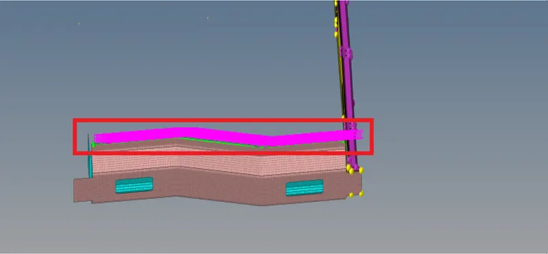
| Figure 63-Realized Connector With Rigid Element Type |
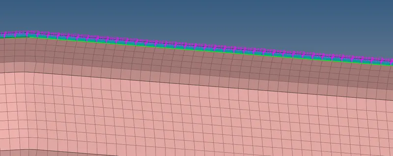
| Figure 64-Proper Representation of Realized Connector With Rigid Element Type |
- Now Realize the connector on Left_Rail_1,Left_Rail_2 component.
- While realizing the connector on Left_Rail_1,Left_Rail_2 component's.Make sure are giving a realization type-spring(ELAS1).
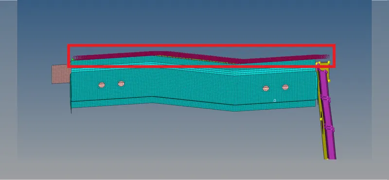
| Figure 65-Realized Connector With Spring(CELAS1) Element Type |
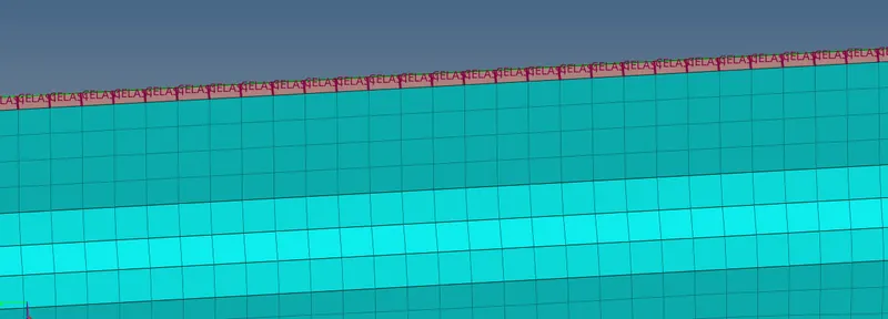
| Figure 66-Proper Representation of Realized Connector With Spring(CELAS1) Element Type |
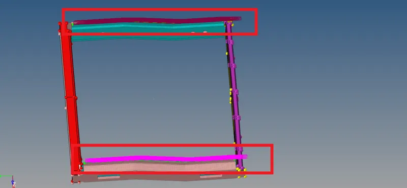
| Figure 67-Connector's on Right_Rail_1,Right_Rail_2 to the Left_Rail_1,Left_Rail_2 component's has been successfully realized. |
- Check the status of the connector's whether they are realized or unrealized or failed.
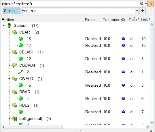
- Here every component's has been realized.
| Figure 68-Realized Connector's |
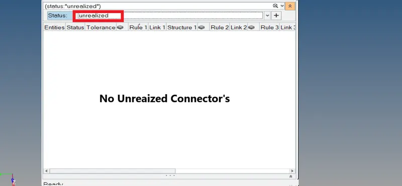
| Figure 69-No Unrealized Connector's |
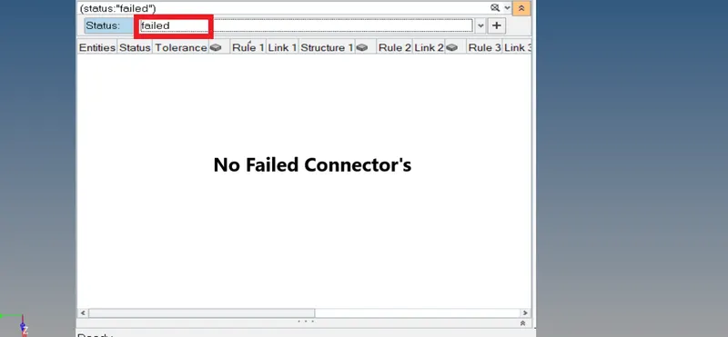
| Figure 70-No Failed Connector's |
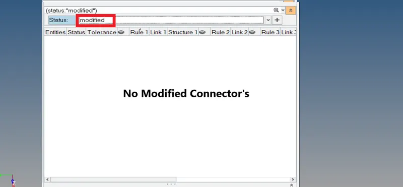
| Figure 71-No Modified Connector's |
Connector's File's[Master Connector File,.mcf,.xml]-
- These master connector files are used to import the connectors into solver desks or other pre-processing software like Abaqus etc.
How to export connectors?
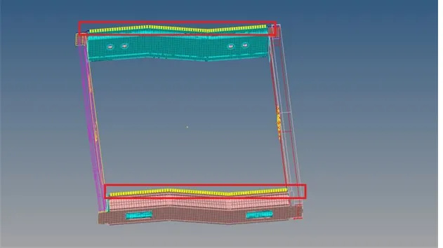
| Figure 72-Connector's Created to Export |
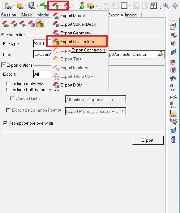
| Figure 72-Export Panel |
- Here select export connector's and select the file type as .xml and give a file name & save the connector file where you want.
How to Import connectors?
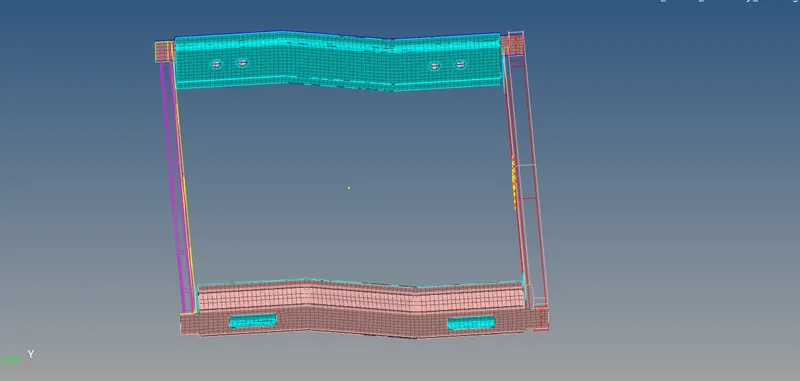
| Figure 73-Now Importing connector's into this component |
- After importing connector's, The imported connector's will lie on the same component, with the same dimension. with the same particular region.
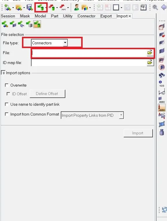
| Figure 74-Import Panel |
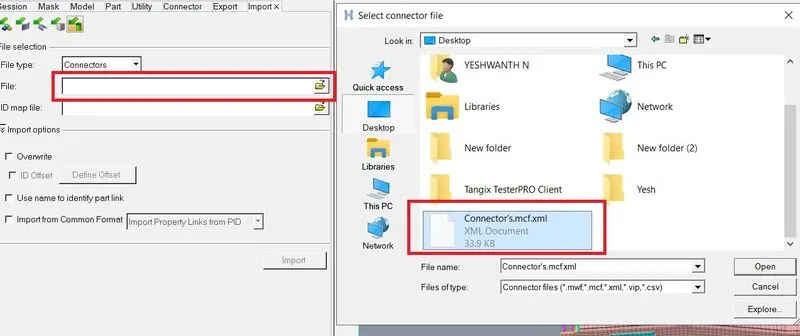
| Figure 75-Connector File |
- After Importing the connectors to the components. Go and realize the connectors. While realizing the connector's, Make sure to change the realization type.
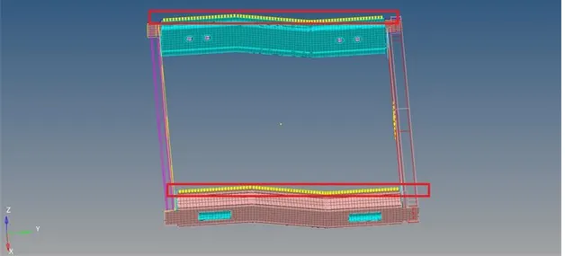
| Figure 76-Imported Connector's |
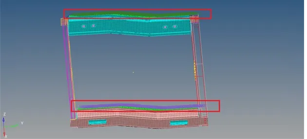
| Figure 77-Connector's has been realized after importing them. |
Final CAD Model Image -
- After Deploying Connector's to the Component's.
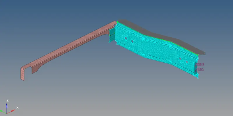
| Figure 78-Right_Rail_2 & Front_truss_1 |
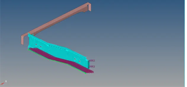
| Figure 79-Left_Rail_2 & Front_truss_1 |
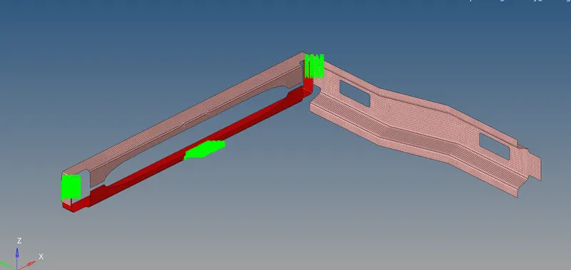
| Figure 80-Front_truss_2, Front_truss_1 & Right_Rail_1 |
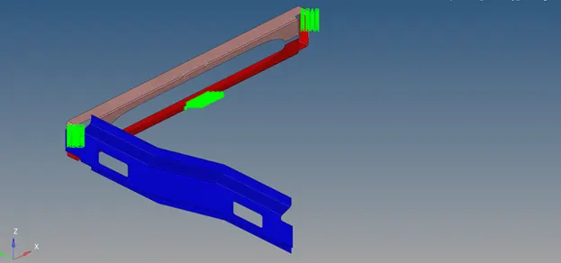
| Figure 81-Front_truss_2, Front_truss_1 & Left_Rail_1 |
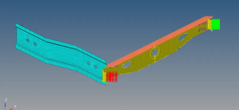
| Figure 82-Rear_truss_2 & Left_Rail_2 |
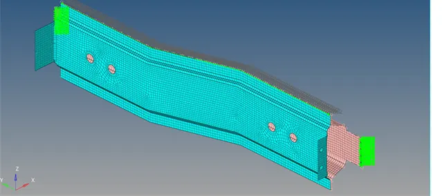
| Figure 83-Right_Rail_1 & Right_Rail_2 |
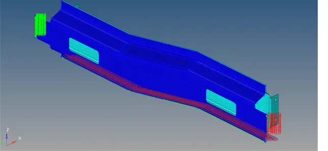
| Figure 84-Left_Rail_1 & Left_Rail_2 |
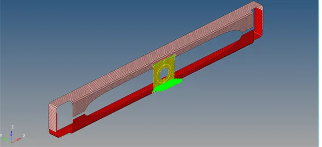
| Figure 85-Rest of the Component's |
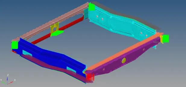
| Figure 86-Successfully Deployed Connector's |
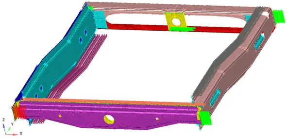
| Figure 87-Proper Representation of Connector's |
Result -
- Hence the given component has meshed with the target element size of 5 units.
- Hence the connector's has been deployed to the components without any glitch.
- Hence the connector's with a proper realization type has been deployed successfully.
Conclusion and Learning Outcome -
- The Assembly Frame has meshed successfully.
- All the connectors have been deployed efficaciously according to the realization type given in the challenge.
- In this Week 9 Challenge, I came to know how to deploy a connector with a suitable realization type.
- How to debug a connector, If it is unrealized, If it is failing.
- How to create a connector in a particular region and reflect a connector.
- To import and export master connection files like MCF (master connectors file).