Week 9-Creation of 1D Connectors Challenge
Aim :-
To deploy connections to the given model after meshing using Hypermesh.
Quality Criteria :-
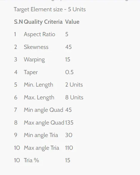
Procedure :-
1. Import the CAD geometry to Hypermesh.
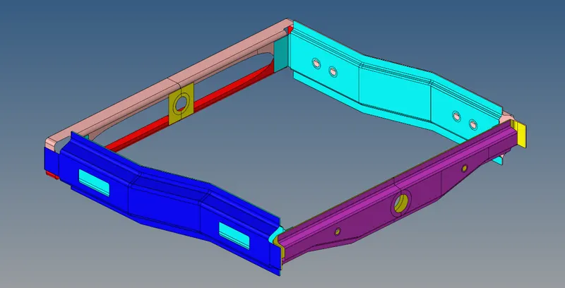
Fig 1 :- CAD Geometry Import
2. Clean-up the geometry if there are any errors using Geometry->Quick Edit->Toggle/Split/Filler/Delete->OK.
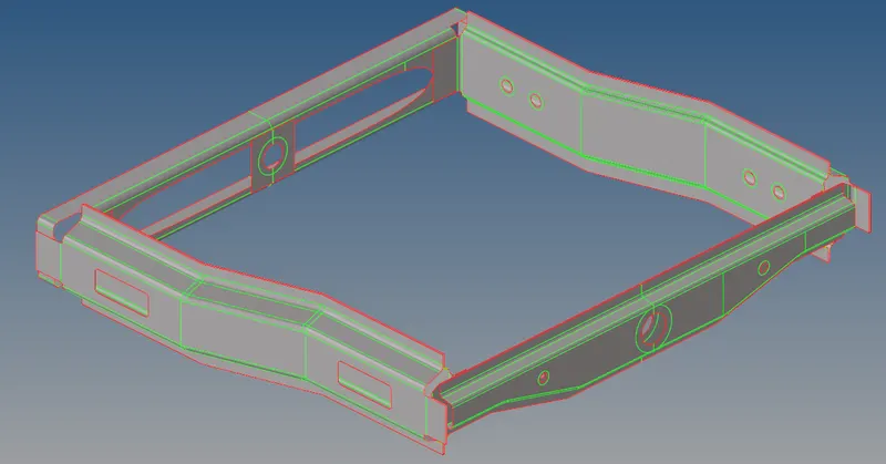
Fig 2 :- Geometry Clean-up
3. Mesh the components one by with with a target element size of 5 units by using 2D->Automesh->Select Surface->Mesh.
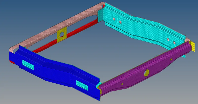
Fig 3 :- Surface 2D Meshing
4. Once the meshing is completed, move to 1D connectors for connecting the components.
4.1. Right_Rail_2 & Front_Truss_1 :- Seam-Quad (angled+capped+L)
Isolate these 2 components and connect by a seam-quad connector using 1D->Connectors->Seam->Select node path->Select the components->Create.
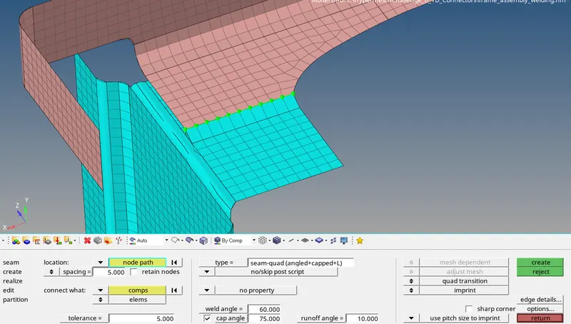
Fig 4.1 :- Seam Quad (Angled+capped+L) Connection
4.2. Left_Rail_2 & Front_truss_1 :- Quad Element
Connect these 2 components using 1D->Connectors->Seam->Enter all 3 angles->Select node path->Select the components->Create.
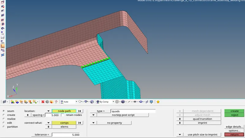
Fig 4.2 :- Seam Quad Connection
4.3. Front_Truss_2, Front_Truss_1 & Right_Rail_1 :- Spot weld with 3 layers & 5mm diameter
Isolate the 3 components, Connect the components Using 1D->Connectors->Spot->Diameter=5units->Node Selection->Compenent Selection->Create.
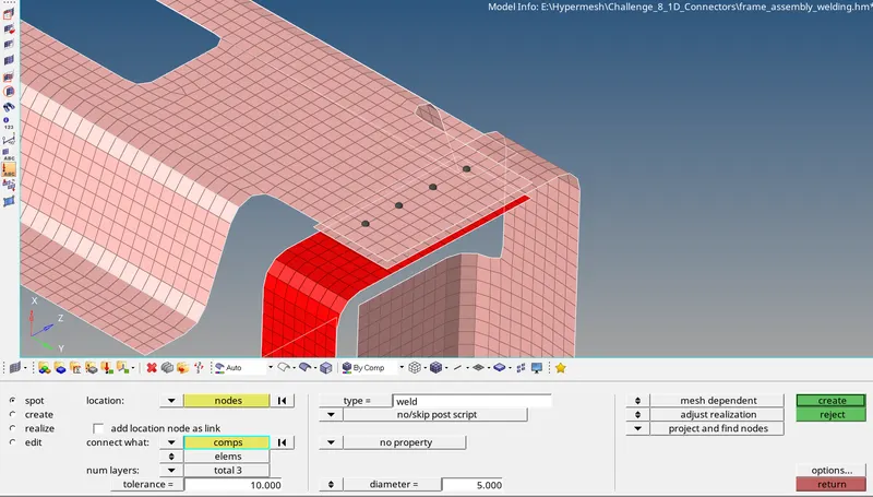
Fig 4.3 :- 3 Layers Spot Weld Connection with Diameter
4.4. Front_Truss_2, Front_Truss_1 & Left_Rail_1 :- Hexa (Adhesive)
Isolate the 3 components, using 1D->Connectors->Seam->Type=Hexa(Adhesive)->Node List Selection->Component Selection->Create, connect the components.
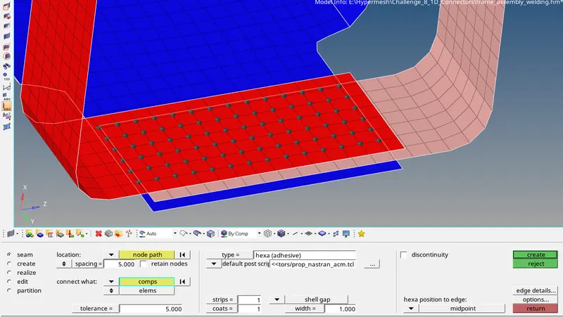
Fig 4.4 :- Hexa (Adhesive) Connection
4.5. Rear_Truss_2, Right_Rail_2 & Left_Rail_2 :- Bolt Connection
Access the bolt connection by 1D->Connectors->Bolt->Type=bolt(CBAR)->Create hole, if none->Nodes Selection->Component Selection->Create.
Rear_Truss_2 is common for both the Rails, hence the same procedure needs to be followed one after the other.
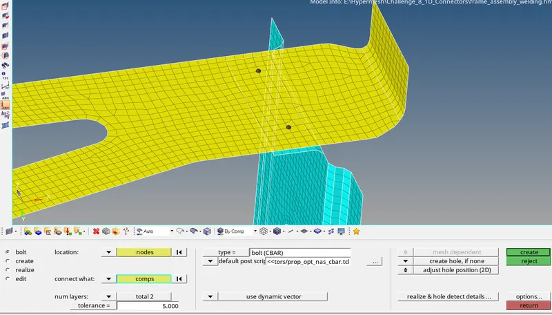
Fig 4.5 :- Bolt Connection
4.6. Right_Rail_1 & Right_Rail2 :- Spot weld with rigid elements
Spot welding is carried out along the side surface by using 1D->Connectors->Spot->Type=Rigid->Nodes->Selection by path->Component Selection->Create.
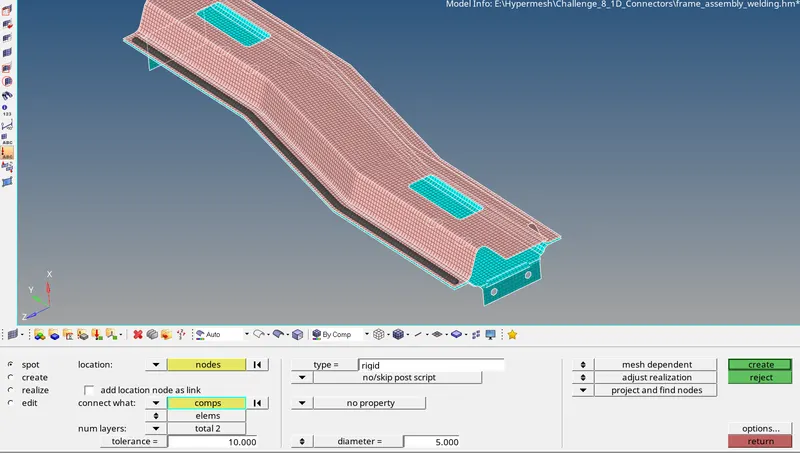
Fig 4.6 :- Spot Weld with Rigid Element Connection
4.7. Left_Rail_1 & Left_Rail2 :- Spot weld with spring elements
Spot welding is carried out along the side surface by using 1D->Connectors->Spot->Type=Spring->Nodes->Selection by path->Component Selection->Create.
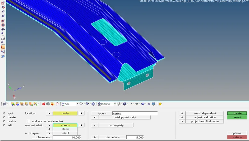
Fig 4.7 :- Spot Weld with Spring Element Connection
5. Connect the remaining components by using suitable connectors similarly.
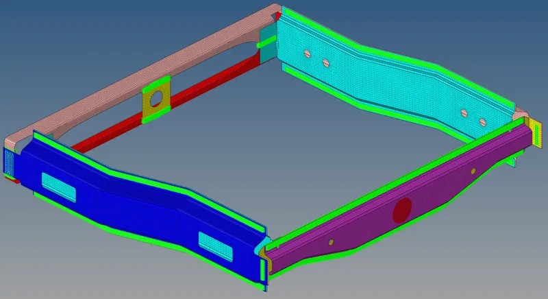
Fig 5 :- Remaining Connections
6. After each connection, the mesh flow gets disturbed. Remesh the connection area either by using Rebuild mesh or Automesh elements.
The quality of mesh should be taken care.
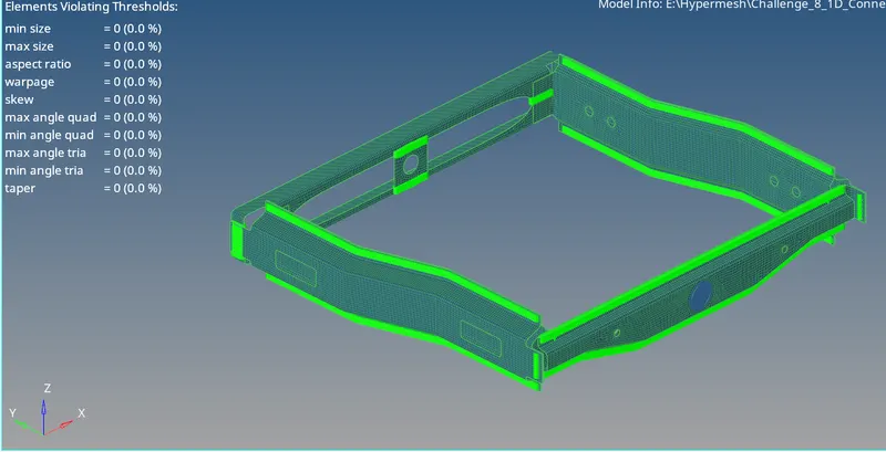
Fig 6 :- Mesh Quality
Result :-
The given CAD model is meshed within the prescribed quality criteria and connections are deployed based on the given condition and are realized.