Creation of 1D Connectors
Creation of 1D Connectors Challenge
Objective :
To mesh the geometry as per the given quality criteria and creation of 1D connectors and attach the various parts of the given model.
The following connections are made to attach the different parts of the model.
1. Right_Rail_2 & Front_truss_1:- Seam-Quad(angled+capped+L)
2. Left_Rail_2 & Front_truss_1:- Quad elements
3. Front_truss_2, Front_truss_1 & Right_Rail_1:- Spot weld with 2 Layers and 5 mm Diameter
4. Front_truss_2, Front_truss_1 & Left_Rail_1:- Hexa (Adhesive)
5. Rear_truss_2 & Right_Rail_2:- Bolt Connector
6. Rear_truss_2 & Left_Rail_2:- Bolt Connector
7. Right_Rail_1 & Right_Rail_2:- Spot-weld with Rigid Elements
8. Left_Rail_1 & Left_Rail_2:- Spot-weld with Spring Elements
PROCEDURE
- Import the geometry using import solver deck and import geometry by selecting file type and click import.
- Enable By topo in visualization toolbar to visualize in topology display mode.And enable display fixed points in display toolbar.
- Mesh each part of the component separately as per the given criteria
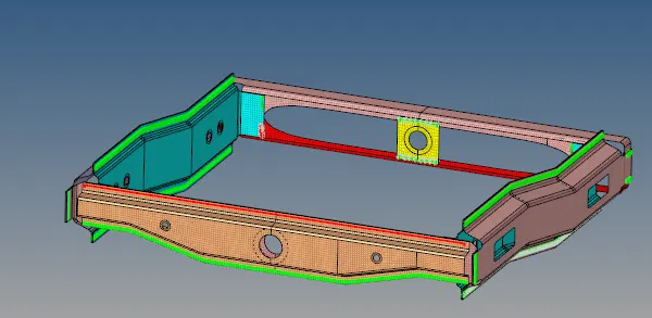
1) Right_Rail_2 & Front_truss_1:- Seam-Quad(angled+capped+L)
- Create a seam by selecting seam quad in connectors. Connectors>Seam>Type-Seam Quad(angled+capped+L),tolerance - 5, select nodes and components right rail2 and front truss 1.
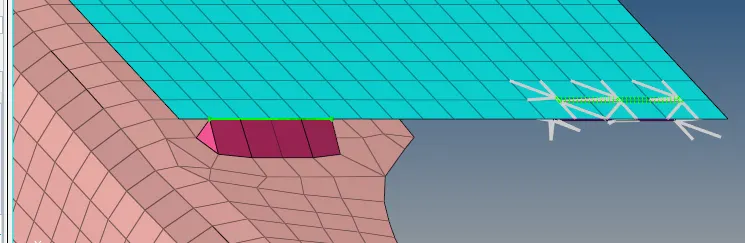
2) Left_Rail_2 & Front_truss_1:- Quad elements
Create quad elements to connect left rail 2 and front truss 1.
Connectors>Seam>Quad>Select nodes by path,and components left rail 2 and front truss 1 and tolerance 5.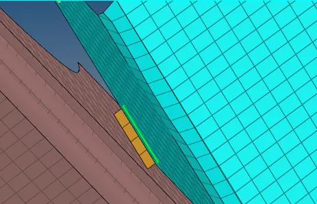
3. Front_truss_2, Front_truss_1 & Right_Rail_1:- Spot weld with 2 Layers and 5 mm Diameter
Create spot weld between front truss 2,front truss1 and right rail 1.
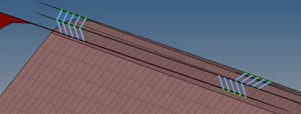
4. Front_truss_2, Front_truss_1 & Left_Rail_1:- Hexa (Adhesive)
Connect front truss 1, front truss 2 and left rail 1 with Hexa Adhesives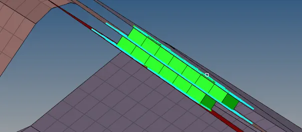
5. Rear_truss_2 & Right_Rail_2:- Bolt Connector
Conncet rear truss 2 and right rail 2 using bolt connector.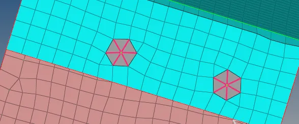
6. Rear_truss_2 & Left_Rail_2:- Bolt Connector
Connect rear truss 2 and left rail 2 with bolt connector.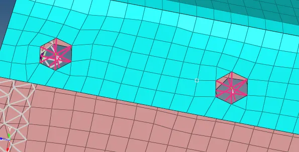
7. Right_Rail_1 & Right_Rail_2:- Spot-weld with Rigid Elements
Connect right rail 1 and right rail 2 by spot weld using rigid elements.
8. Left_Rail_1 & Left_Rail_2:- Spot-weld with Spring Elements
Connect left rail 1 and left rail 2 by spot weld using spring elements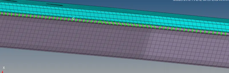
Other parts are connected by spot weld and adhesives
Conclusion
The model is meshed as per the given quality criteria and the various parts of the given model are connected using 1D connectors.