Week 9 - Creating connection for Rear door
AIM:
To create and apply different PID’s and deploy FE connections to the given rear door FE model.
PROCEDURE:
1.Import the given FE rear door model into the ANSA work area and analyze the different parts present in the model, and create PID’s to apply for each part
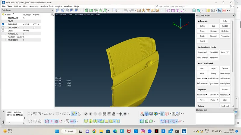
Given FE model.
Since the given FE is modelled using shell elements, we create PID for shell elements PSHELL in ANSA.
To create PID: LISTS > PROPERTIES > RIGHT CLICK / NEW > NEW > PSHELL > PSHELL
Apply the PID to the desired elements in the model.
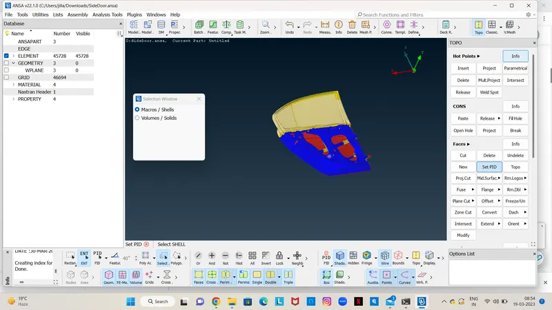
FE after apllying PID.
2.Creating connections.
RBE2 connection:
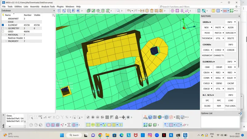
a) many nodes RBE2
MODULES > DECKS > ELEMENTS > RBE2 > MANY NODES
Select the nodes that are to be connected.
2)Spot weld connection
To create a spot weld connection, firstly a point needs to be created at the point of connection
Convert the point to spot weld: ASSEMBLY > CONVERT > 3D POINT > SPOTWELD POINT
To create spotweld at the point go to: ASSEMBLY > CONNECTION MANAGER > SELECT THE POINT
3)Seam connection
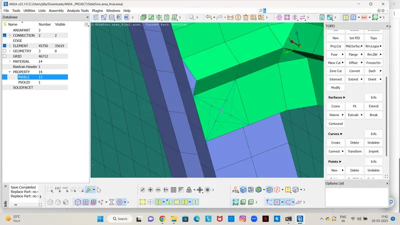
To create a seam connection a curve needs to be defined which acts as a seam line for the connection
Connect the lines using CURVES > CONNECT > MULTI option
Connect the lines using CURVES > CONNECT > MULTI option
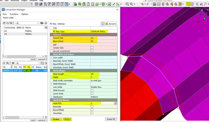
Convert the curve to seam line: ASSEMBLY > CONVERT > CURVES > SELECT THE CURVE > SEAM LINE > OK
The next step is to deploy the overlap-shell connection on the created seam line as shown in the below figure.
4)RBE3-CBUSH-RBE3
The connection between the door window and the weatherstrip will have a CBUSH connection which has stiffness in 3 directions.
To create a CBUSH connection we need a spot line(weld line) at the location of the connection.
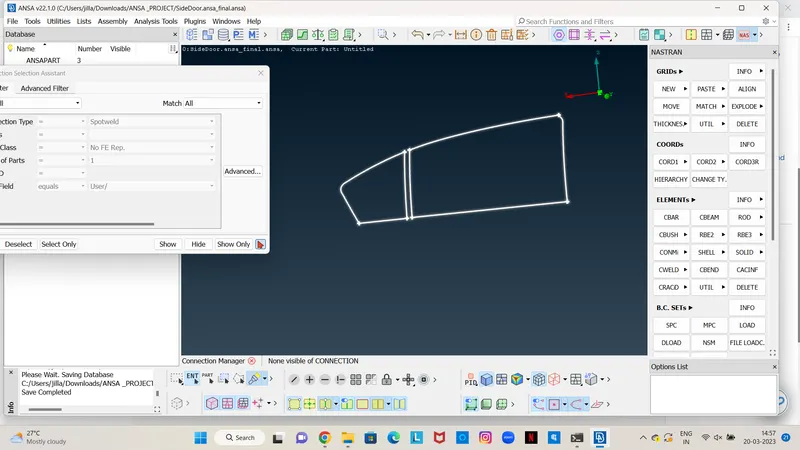
connect the curve and convert the curve to spot line as shown below.
To deploy a CBUSH connection go to ASSEMBLY > CONNECTION MANAGER >SELECT THE CURVE > SELECT FE TYPE = RBE3-CBUSH-RBE3, and select the P1 and P2 as door and window respectively
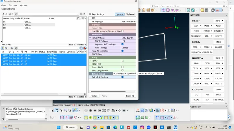
Create a separate PID for PBUSH ID and apply it to the connection.
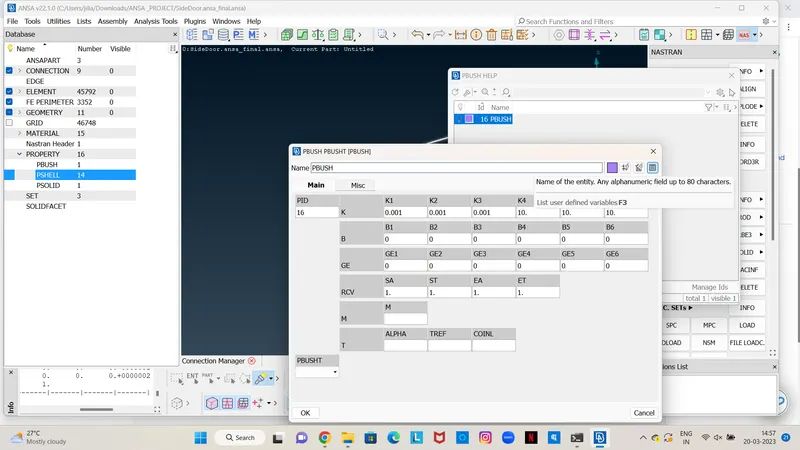
PBUSH PID will allow applying 6 different stiffness values(K1-K6) to the property, as shown in above image.
The orientation of the CBUSH needs to be changed to the global orientation.
To align the coordinate to the global orientation set CID value to zero, as shown in the below image
Learning outcome:
- Introduction to connection manager and convert option in assembly module.
2.Different connection options available in ANSA, such as Two Nodes RBE2, RBE3-CBUSH-RBE3, Nut and Bolt representation and Seam weld data representation
3.Generating connections to the automotive rear door part, and seating parts.
Conclusion:
Different connections have been generated on the given rear door part to represent the real door connection to the vehicle body, the orientation of CBUSH elements are aligned to the global coordinate system.