Week 9 - Creating connection for Rear door
Deploying Connectors for a Rear Door of a Car
Aim -
- To Deploy a appropriate connectors for a Rear Door of a Car.
Objective -
- Creating a property id's for door hinges and deploy a bolt connectors.
- Creating RBE2 1D Elements for bolt joints.
- Creating RBE3-CBUSH-RBE3 element for the weather strips.
- Creating RBE3-HEXA-RBE3 element for the spot weld joint.
- Creating RBE2 Element and Applying mass for a door handle.
Theory of Connector's and their terminologie's -
Connectors Definition :
- They are geometric entities (not FE) primarily used to create spot- and seam welds, but also used to create adhesives, bolts and masses.
- They are simply a database of information defining specific requests for connections at specific locations.
- They are a medium to create both solver independent and/or solver dependent connections between geometric and/or FE entities.
- They can be created interactively or from different master connection files (.xml, .mcf, .vip).
Types of Connector's :
Spot-
- Connections at a point.
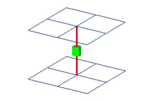
| Figure 1-Spot |
Bolt-
- Connections at hole locations.
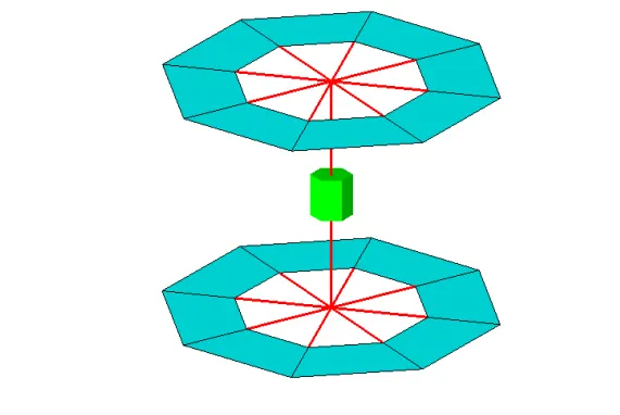
| Figure 2-Bolt |
Trim Mass-
- Non-physical mass.
- Simplification through replacement of parts with mass only or add mass to existing part.
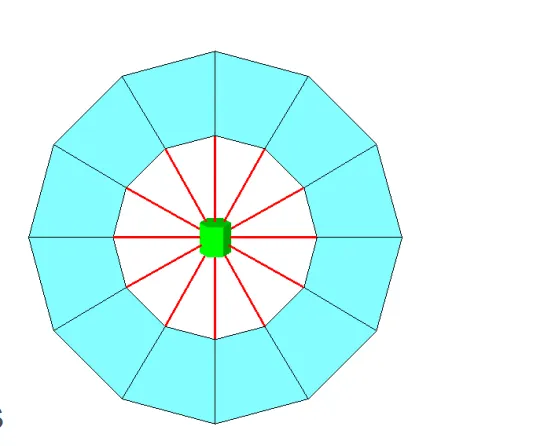
| Figure 3-Trim Mass |
Seam-
- Connections along a length.
- Seam welds.
- Connects geometry only.
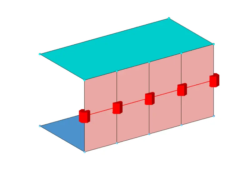
| Figure 4-Seam |
Area-
- Connection of areas.
- Adhesives.
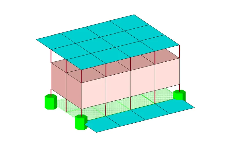
| Figure 5-Area |
Connectors-Terminology
Link Entities - The entities that are being connected.
- User can explicitly define link entities or specify a search tolerance.
- Can be components, elements, surfaces, nodes, or tags.
- Typically components are linked.
Connector Location - Where the entities are linked.
- Nodes – created at the node location.
- Points – created at the point location.
- Lines – created for the line line may be split into multiple projection locations as specified by the offset, spacing, and density values.
- Elements – created at the element location (adhesives only).
- Surface – created at the surface location (adhesives only).
Connector Realization – The creation of the finite element representation of that connector.
- Rigids, springs, etc., or custom configurations such as ACMs, CWELDS, etc.
Three Types of Connector's State – Whether an FE representation of a connector has been created.
1) Unrealized - The initial status of the connector entity upon creation.
- Newly created or imported connector before the first realization.
- Editing the connector definition (i.e. add or delete a link entity from the connector), the connector removes the welds it created, and reverts back to an unrealized state.
- Manual unrealization.
2) Realized - The status only if creation of the FE weld representation at the connector was successful.
3) Failed – The status if the creating the FE weld representation at the connector was not successful(Failed).
- If the creation of the FE representation is unsuccessful (due to low tolerance, insufficient link entities, etc.) the connector icon is displayed as failed (red).
These are the Connection's which are used mostly in industries-
- Seam Weld
- Spot Weld and
- Bolt Weld
Seam Welding and it's Apllication's-
- Seam welding is the joining of work pieces made of similar or dissimilar materials along a continuous seam. Seam welding can be broken down into two main techniques, resistance seam welding and friction seam welding.
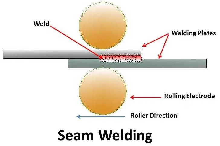
| Figure 6-Seam Weld |
- It is used for welding of stainless steels, steels alloys, nickel and its alloys, magnesium alloys etc
Spot Welding and it's Apllication's-
- Spot welding (or resistance spot welding) is a type of electric resistance welding used to weld various sheet metal products, through a process in which contacting metal surface points are joined by the heat obtained from resistance to electric current.
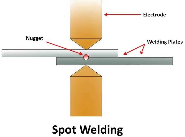
| Figure 7-Spot Weld |
- Spot welding is typically used when welding particular types of sheet metal, welded wire mesh or wire mesh.
Bolt Connection's Model-
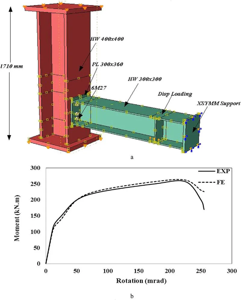
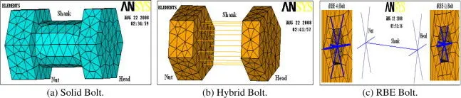
| Figure 8-Bolt Connection's |
Procedure -
- Deploying connector's in the sense,A type of joining operation which is used to combine the different component's of an assembly.
Phase 1-Importing the CAD Model
- Hence we are importing a given CAD geometry into the ANSA.
- There are file formates like IGES,STEP,Parasolid where we can import these file formats into any CAD,CAE Softwares.
- In ANSA we can import all the CAD Software file formates like
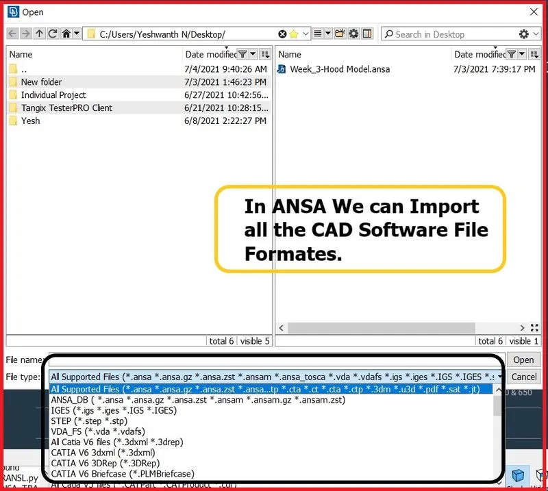
| Figure 9-Supported File Formats. |
- IGES [Initial Graphics Exchange Specification].
- STEP [Standard for the Exchange of Product Model Data].
- Solidworks.
- Catia V5,V6
- Simens NX CAD
- Inventor
- Creo
- Solid Edge
- Rhinoceros 3D
- IGES,STEP,These two are standard file formats which are mostly used in industries.But now a days in industries,they are aslo using parasolid file format.
- Now import the model into ANSA GUI.The Model given to us is in STEP File Format.
- Go to Main Pull Down Menus >> File >> Open.
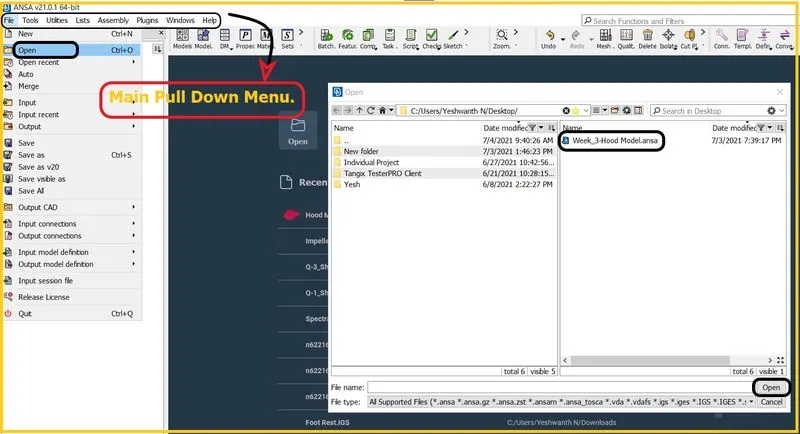
| Figure 10-Importing/Opening the Model. |
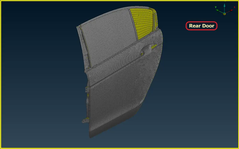
| Figure 11-Model Imported into GUI. |
Phase 2- Create Property ID's for Hinges
- To Create Property ID,Go to Topo Module >> Set PID >> Select Faces >> Middle Click >> New Window Will Pop Up >> Right Click >> New >> PSHELL.
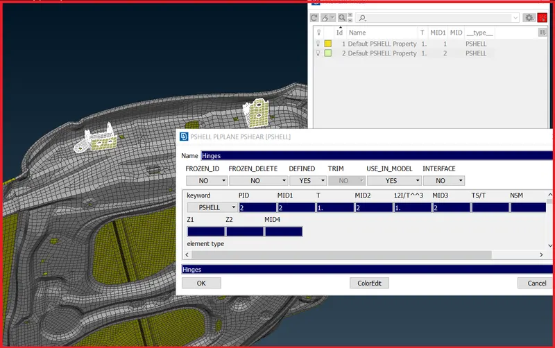
| Figure 12-Creating PID's for Hinges. |
- After creating different property ID's for hinges,Deploy a bolt connector to the hinges.
Deploying Bolt Connectors in Hinges -
- To deploy a bolt connector.
- First create a COG point in the circular edges using edges option.
- To Create COG Point,Go to Topo Module >> Points >> On COG >> Edges.
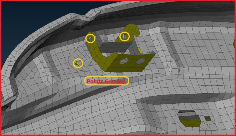
| Figure 12-Points Created. |
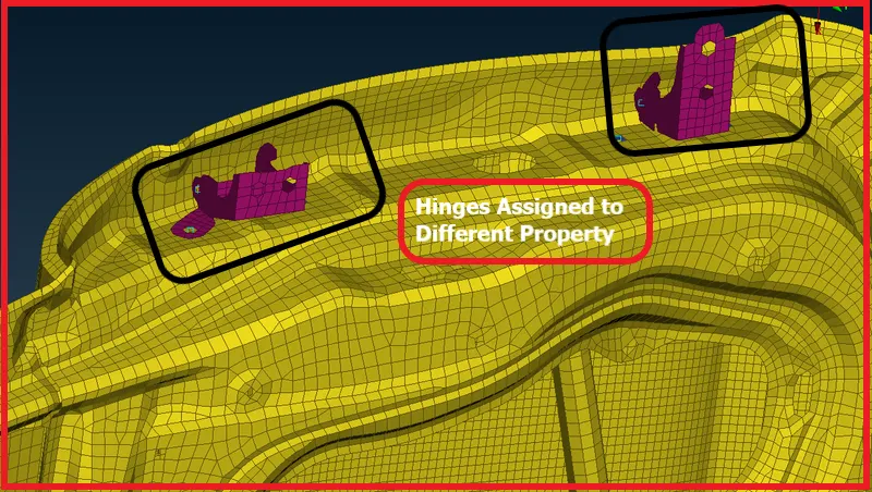
| Figure 13-Hinges have been assigned to different property. |
- After assigning hinges to the different properties.
- Convert that points to the bolt.To convert,Go to Utilities >> Convert >> 3D Points >> Bolt >> Select the Points >> Middle Click.
- Next deploy a connector,Go to Utilities >> Connection Manager >> Select Entities.
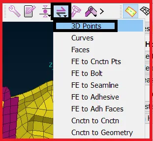
| Figure 14-Converting the Point to 3D. |
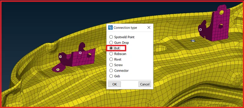
| Figure 15-Connection Type. |
- Go to the connection manager and select the bolt to deploy a connector.
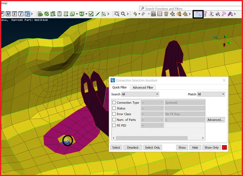
| Figure 16-Connection Slection Assistant. |
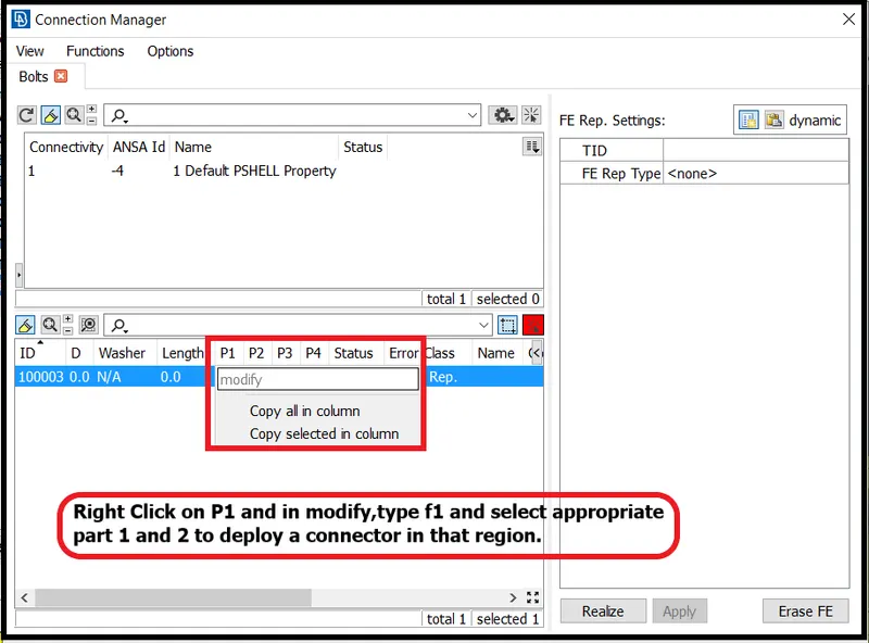
| Figure 17-Connection Manager. |
- Right Click on P1,P2 and in modify,type f1 and select appropriate part 1 and 2 to deploy a connector in that region.
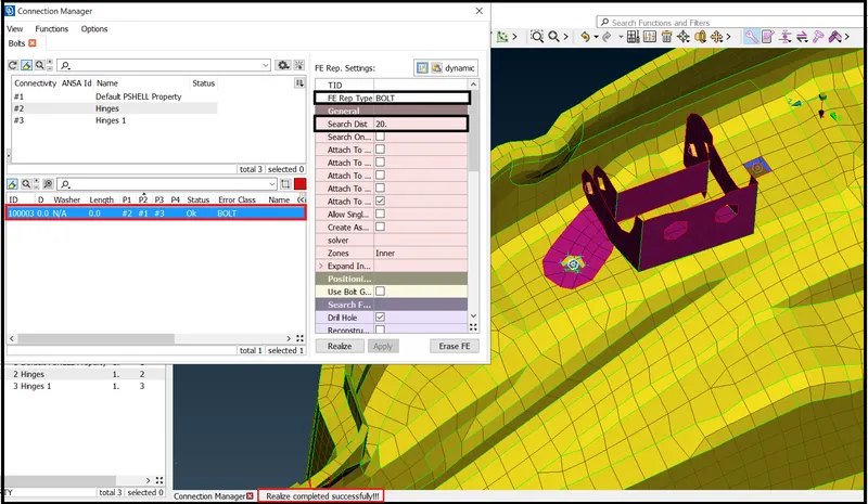
| Figure 18-Bolt Connector Deployed and Realized Successfully. |
- Similarly do the same process in every region where the bolt connection is required.
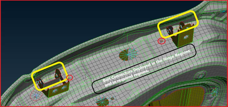
| Figure 19-Bolt Connectors Deployed in Required Regions. |
Creating RBE2 Elements in Requied Regions -
- RBE2 Element - The RBAR or RBE2 element can be used for connecting two nodes to model a 'rigid' welded type connection, with all 6 DOFs, or a pinned connection with 3 translational DOFs. The RBE2 element can also be used to model a wagon wheel type connection between the independent and the dependent nodes.
- The RBE2 Element represents the bolts and rivets,so that's why we are using RBE2 Elements to represent the bolts.
- To create RBE2 Elements,Go to Nastran Deck Module >> Elements >> Many Nodes.
- We can create RBE2 Elements by two methods called Cluster and 3D Point.
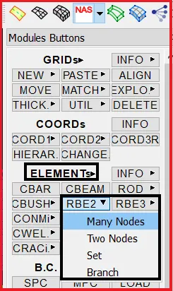
| Figure 20-Elements Nastran Deck. |
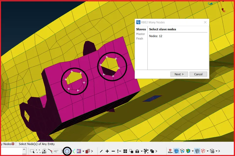
| Figure 21-Creating RBE2 Elements to Represent Bolt. |
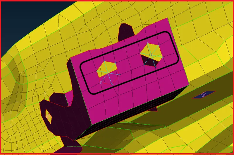
| Figure 22-Created RBE2 Elements. |
- Simillarly do the same thing in every required region.Create RBE2 Elements in required regions to represent Bolts and Rivets.
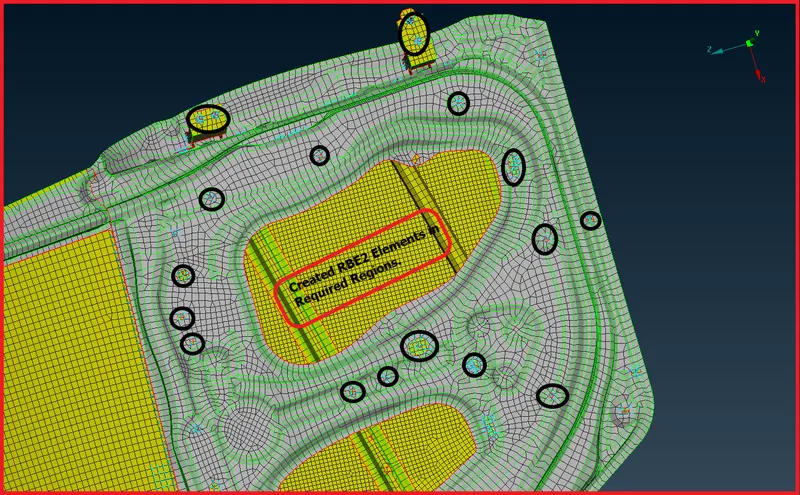
| Figure 23-Created RBE2 Elements in Required Regions. |
Creating Cluster RBE2 Elements -
- To create RBE2 Elements,Go to Nastran Deck Module >> Elements >> Many Nodes.
- First,Select the slave nodes which is dependent nodes and then followingly click the middle mouse buttom, it will automatically find the master location & create the node by itself which is nothing but a independent node.
- If we use this method, it will have multiple number of dependent nodes and only one independent node.
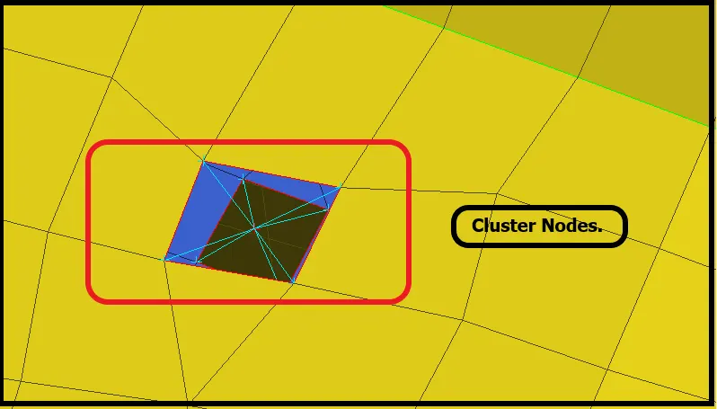
| Figure 24-Created Cluster RBE2 Elements. |
Creating Connection Between Rail and Glass -
- To Create a connection between rail and glass,Hide the unnecessary regions and isolate only glass and rail.
- And create a connection using Cluster RBE2 Elements.
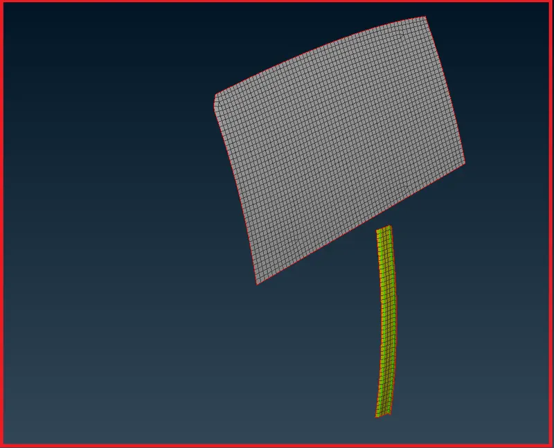
| Figure 25-Glass and Rail. |
- Now extend a rail near to glass using Move Free tool.
- Go to >> Mesh Module >> Grids >> MV Free >> Select the Nodes.
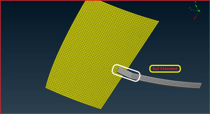
| Figure 26-Rail Extended. |
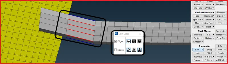
| Figure 27-Splitting using Opposite Path Tool. |
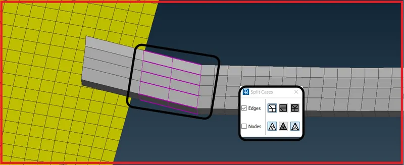
| Figure 28-Splitted two row of elements using Opposite Path Tool. |
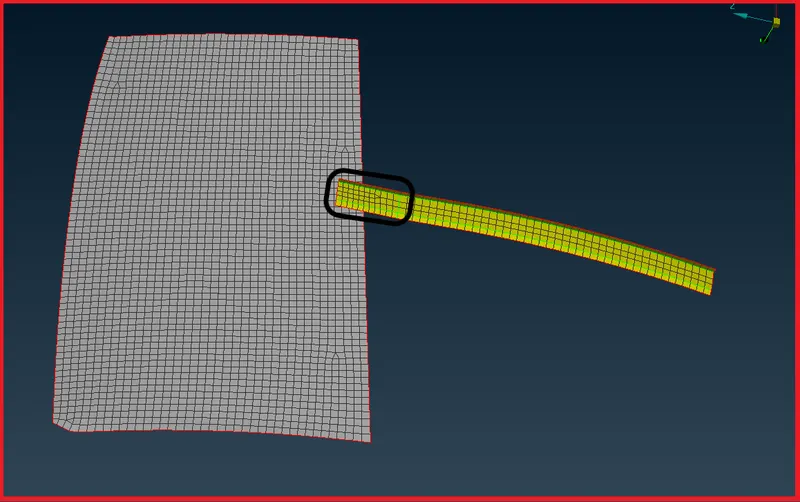
| Figure 29-Splitted the elements uniformly. |
- Now select the slave nodes to create a RBE2 Elements to connect the rail and glass.
- To create go to Nastran Module >> Elements >> RBE2 >> Many Nodes.
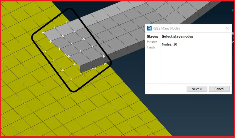
| Figure 30-Slave Nodes Slected to create RBE2 Elements to connect Rail and Glass. |
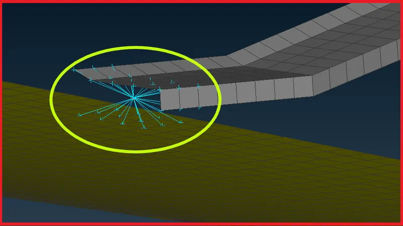
| Figure 31-Rail and Glass has been connected by creating RBE2 Elements. |
Creating Connection for Door Handle and applying mass -
- For the handles, which are presented in the door, we have to represent that part with mass concentration node.
- First,Create a RBE2 elements with multiple slave nodes and single node on both holes at where handle has bee fixed in rear door.
- To assigning the mass concentration, we have select the [CONMi] element.
- Go to the NASTRAN Deck modules >> Elements >> CONMi >> CONM2.
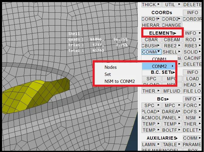
| Figure 32-Elements Panel. |
- Now create a RBE2 for the door handle.
- After Creating RBE2 elements.
- Create a RBE2 element using many nodes to create a master node,then only we will be able to assign a mass to the door handle.
- To create master node,Go to Nastran Deck Module >> Elements >> RBE2 >> Many Nodes.
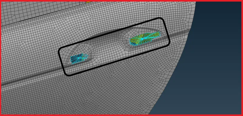
| Figure 33-Created RBE2 Elements. |
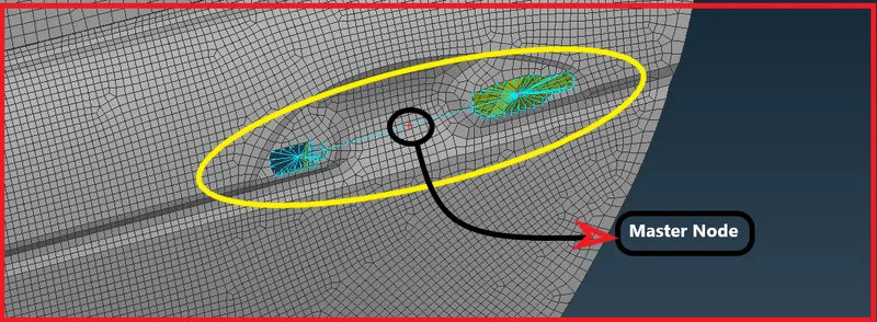
| Figure 34-Master Node Created using Many Nodes. |
- Now Apply Mass.To apply mass,Go to CONMi >> CONM2 >> Nodes from Nastran Deck.
- Now select the master node and middle click,a window will pop up.
- And the mass of handle is assumed rendomly as 100 Grams.
- Here the mass value should be in terms of tonnes.
- So Enter the vaue in tonnes.
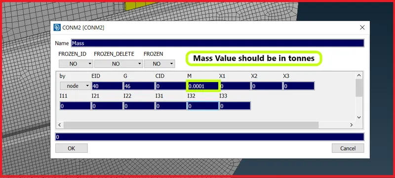
| Figure 35-CONM2 Panel. |
[Note : 1 Tonne = 1000000 Grams
Tonne (Metric ton) is a unit of mass in the Metric system. 1 tonne = 1000000 (one million) grams.]
Deploying Spot Weld Connection -
- To Deploying a spot weld connector,We need COG Point.
- Create a COG Point,To create a COG point,Go to Topo Module >> Points >> On COG >> Edges.
- After creating a COG Point,Convert it as 3D Spot Weld Point using Convert tool from utilities panel.
- Now select that spot weld point to deploy a spot weld connection.
- Connection manager window will pop up.
- Give a appropriate search distance and select the appropriate parts to deploy a spot weld connection.
- In FE representation type,Select RBE3-Hexa-RBE3.
- Now hit on apply and realize the connection,If the connector is not realized,select the appropriate p1 and p2,less search tolerance value,recreate cog point again and deploy a connector.
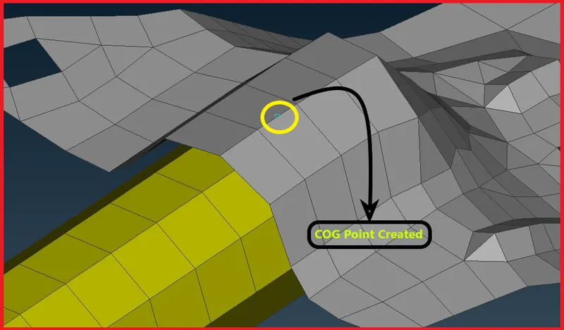
| Figure 36-COG Point Created. |
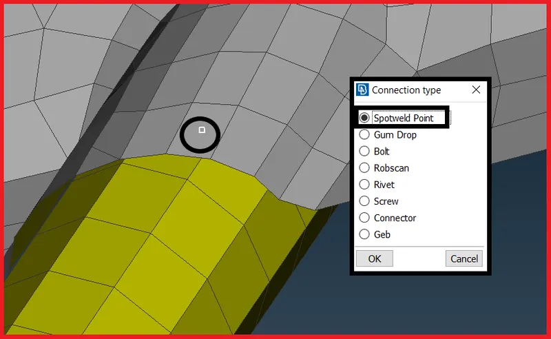
| Figure 37-SpotWeld Point. |
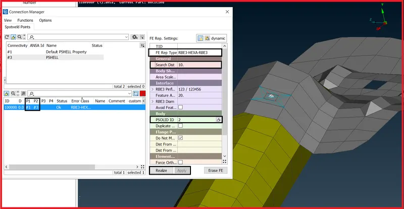
| Figure 38-Connection Manager. |
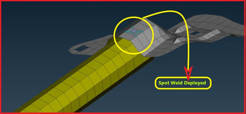
| Figure 39-Spot Weld Deployed. |
Deploying CBUSH Connection -
- To deploy a CBUSH connection,First create a curve where you want to deploy a connection.
- To create a curve,Go to Mesh Module >> Perimeters >> Feature Curves >> Select the element edges >> Middle Click.
- Convert the curves to the seam line curve to deploy a connection.
- To convert,Go to >> Utilities >> Convert >> Spot Line.
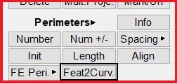
| Figure 40-Perimeters Panel. |
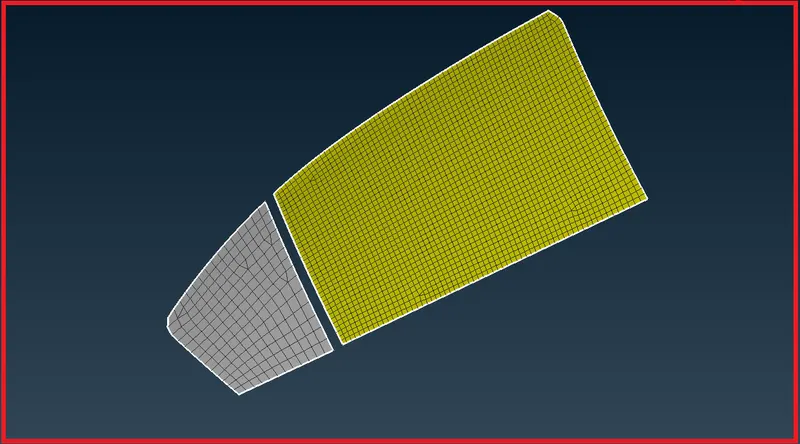
| Figure 41-Selecting the edges to create curve. |
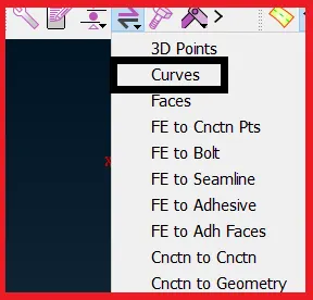
| Figure 42-Convert Tool. |
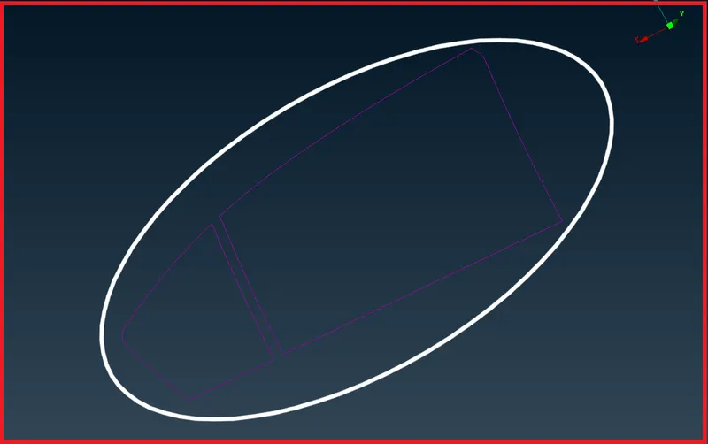
| Figure 43-Curves. |
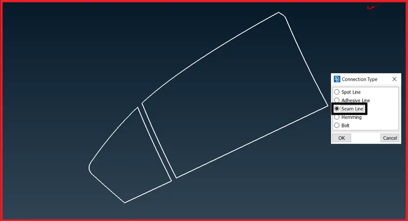
| Figure 44-Selecting the Curves. |
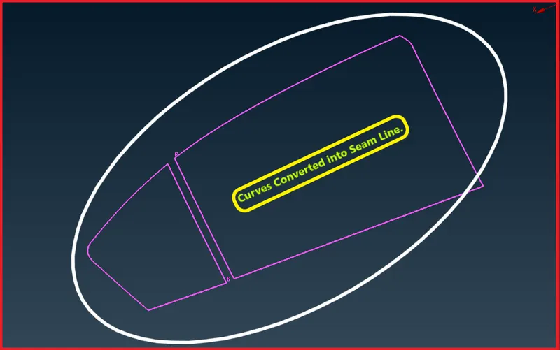
| Figure 45-Curves Converted into Spot Line. |
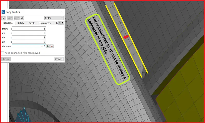
| Figure 46-Curve translated to 10 mm. |
- Now go the connection manager from utilities panel.
- A Connection selection Assistant will pop up.Select the curve and deploy a connection.
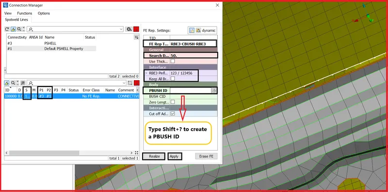
| Figure 47-Connection Manager. |
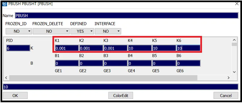
| Figure 48-PBUSH Panel. |
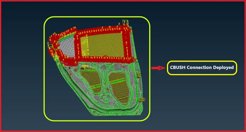
| Figure 49-CBUSH Connection Deployed. |
- Now the CBUSH Connections are not oriented properly,To orient the connections in one direction.
- Go to the Element DataBase.
- Select all the CBUSH Connections and right click on them and click on modify.
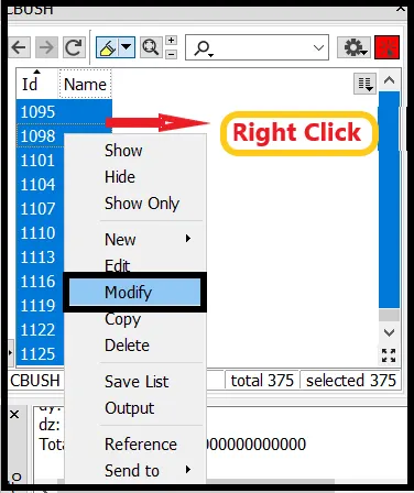
| Figure 50-CBUSH Elements. |
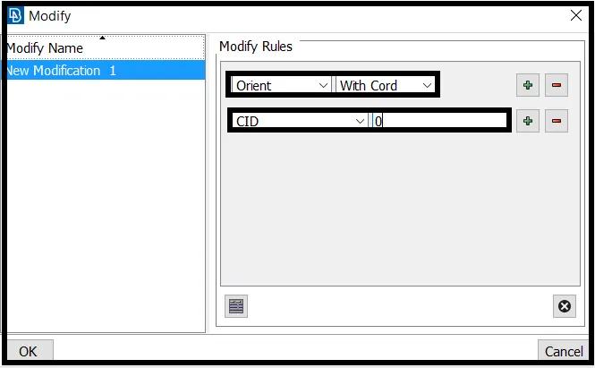
| Figure 51-Modify Panel. |
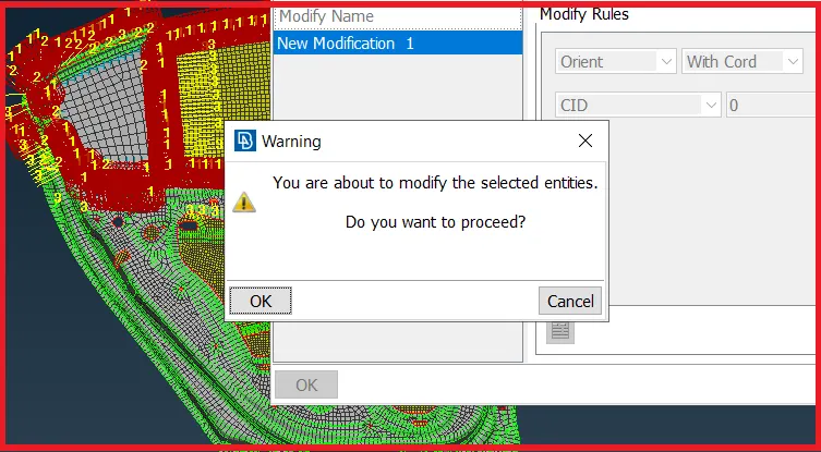
| Figure 52-Modifying the Entities to Orient in One Direction. |
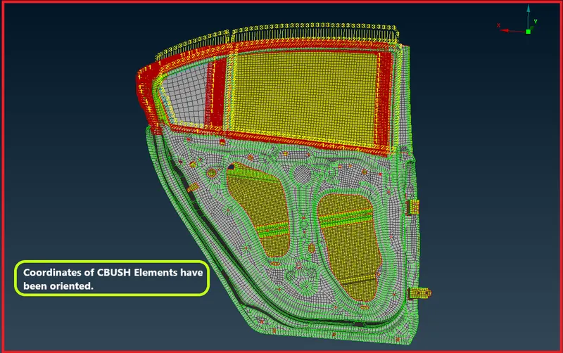
| Figure 53-Coordinates of CBUSH Elements Have been Oriented. |
Final CAD Model Image -
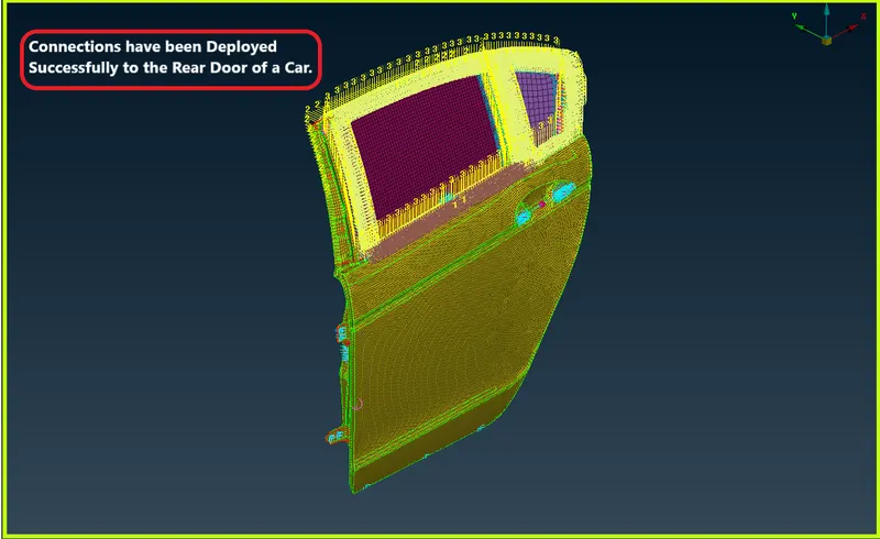
| Figure 54-Final Cad Model Image 1. |
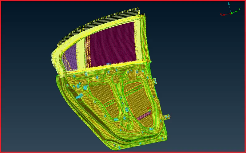
| Figure 55-Final CAD Model Image 1:1. |
Result -
- Hence the Connectors have been deployed successfully to the car rear door component by using RBE2,RBE3-CBUSH-RBE3,RBE3-HEXA-RBE3 and CONMI2 element.
- Hence the connector's has been deployed to the component's without any glitch.
- Hence the connector's with a proper realization type has been deployed successfully.
Learning Outcome's -
- All the connectors has been deployed efficaciously according to the realization type given in the challenge.
- In this Week 6 Challenge,I came to know how to deploy a connector with a suitable realization type.
- How to debug a connector ,If it is unrealized,If it is failing.
- How to create a connecotor in particular region.
- To import and export master connection files like MCF (master connectors file).