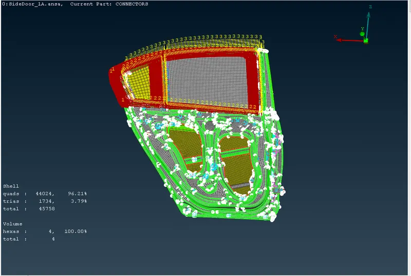
Week 9 - Creating connection for Rear door
CREATING A CONNECTION FOR REAR DOOR
Aim: To create a connector for the given model
Object:
1. To study the model carefully.
2. To understand the types of connector to be used.
3. Implement the particular connector to the given model.
Procedure:
1. Rigid connector: steps to be followed:
a. RBE2 element à many nodes à select the slave nodes à click on next à define a new part
b. To create a group of connection à drag the new connection part outside à drop the new group.
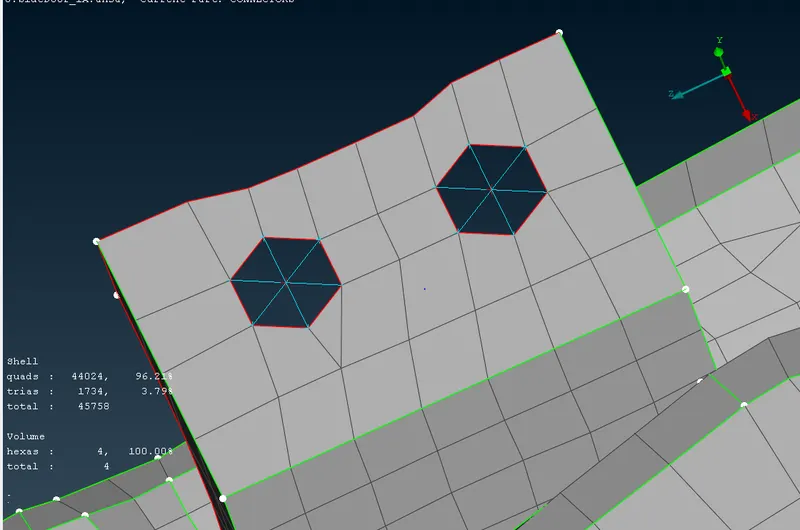
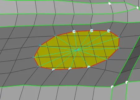
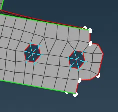
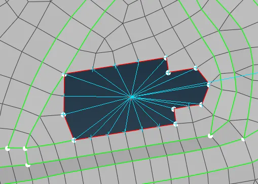
similaraly connecting the parallel feature using same command like
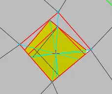
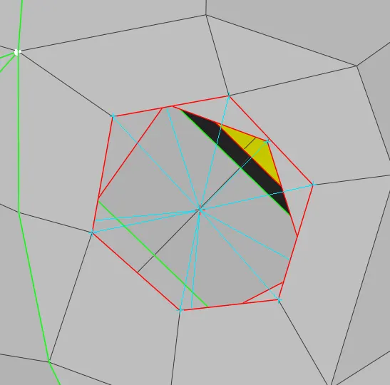
2. creating zone cut and creating the rigid connect
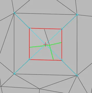
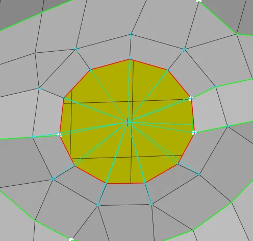
3. Connecting the number slave node by one master node.
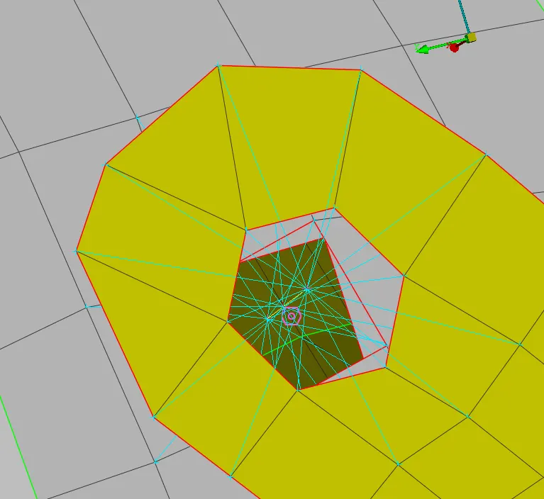
4. In the hinged part: connecting rigid connection into one master connect by constrained, constrained the all the degree of freedom excluding one rotational DOF on Z-axis.
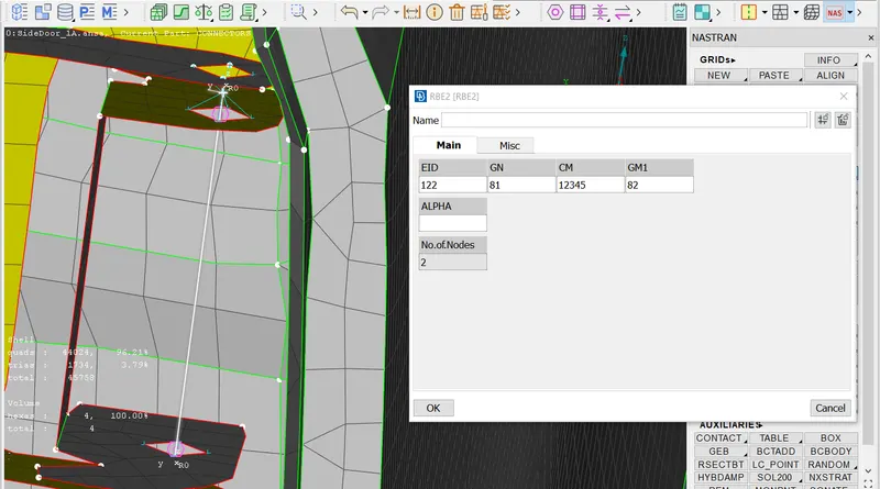
5. creating the mass connector in handle part: steps need to to be followed is
create the rigid connector using RBE2 --> many nodes --> then go to the CONM2 --> select the node --> assign the mass in terms of tonnes.
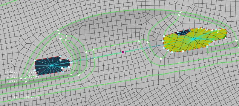
6. creating the spot weld: steps to be followed as follow:
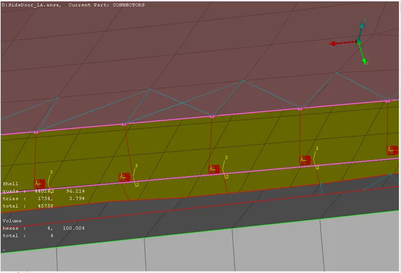
create the COG on where spot weld need to be done --> convert --> click on the COG --> convert into spot weld --> click on the COG and set the P1 AND P2 and type is RBE3-HEXA-RBE3 --> RBE3 pinflags à 123456 --> Create the PSOLID property ID and assign the PID in PSOLID
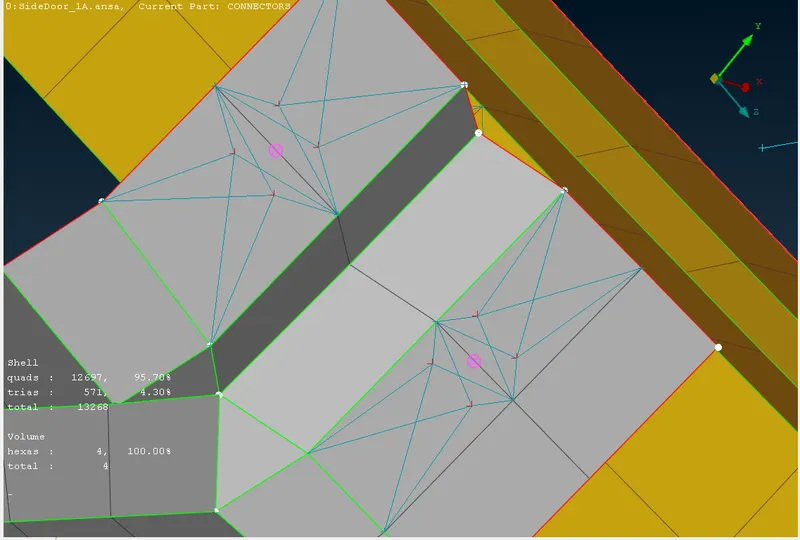
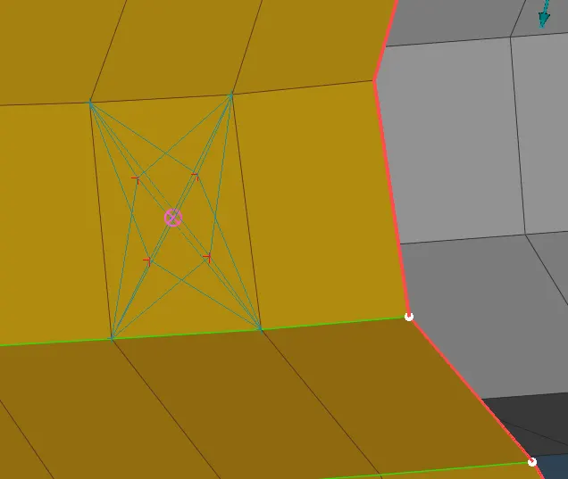
7. interms not able to creating the spot weld. We can use the RBE2 connect the 2 parallel part feature.
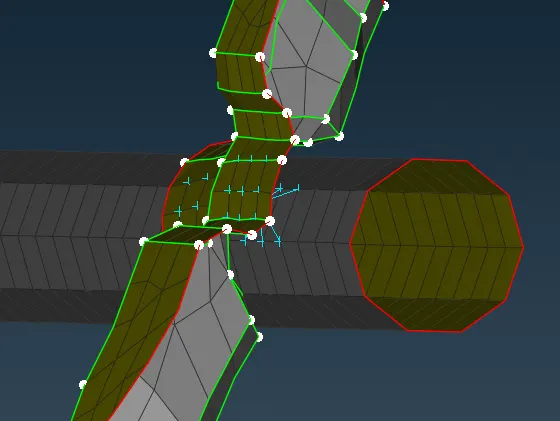
8.CBUSH connector: creating the CBUSH on window panel
Create the curve --> select teh curve --> convert into spot weld line --> connect the created spotweld line --> select P1 and P2 --> Set the search distance as 50 and enable the keep all the branches --> select the particular PBUSH PID --> apply --> realise.
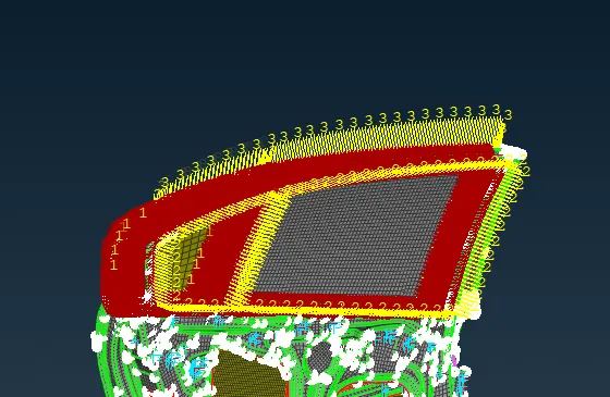
Final model with all the connector: