CREATING CONNECTORS BETWEEN MESHES
CREATING CONNECTORS BETWEEN MESHES
OBJECTIVE:
To create a connector between mesh surfaces.
INTRODUCTION:
Connectors is used to define connections between 2 or more components. It represents FE idealization of physical connections.
Types of connector:
- Seam
- Bolt
- Spot
CONNECTOR CHARACTERISTIC:
- Terminology: Defines connector method (Seam/Bolt/Spot) and State.
- Definition: Defines locations and layers of connections.
- Realization: State of connector.
- Review: Review the existing connectors.
CONNECTOR STATE:
- Realized: Green. (Connector defined perfectly)
- Unrealized: Yellow. (Connectors yet to defined properly)
- Modified: Blue. (Connectors modified after realized)
- Failed: Red. (Connectors failed to realize)
SUB PANEL EXPLANATION:
Column 1:
- Seam/Spot/Bolt -> Create connection and realized.
- Create-> Create only connections.
- Realize-> Realize existing connections.
- Edit-> Delete or remove connectors.
Column 2:
- Location: Nodes/Node list /Lines are selected for connection locations.
- Connect what: Components/Surfaces to be connected.
- Tolerance: Approx. lengths to find elements to next components.
Column 3:
- Type: Connection type with respect to the method of connections.
- Property: Material properties of connections.
Column 4:
- Procedure to make a connection between mesh/Surface is assigned in this column.
Pic 2:

PROCEDURE:
SEAM CONNECTOR:
- Seam connectors connects two or more components along the line or length of the components.
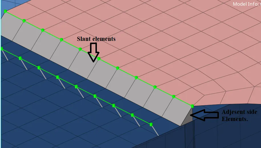
- Seam Quad (Angled+ Capped+ L): Create angled elements in terms of connections. It produces 2 types of elements 1. Slant elements 2. adjacent side elements. As shown in Pic 3.
Pic 3.
- Classifications:
Weld angle: Angle between node projection and slant elements.
Run-off angle: Angle between adjacent surface elements and slant elements
Cap angle: Angle between Adjacent elements and slant elements.
- Connector creation method:
Mesh Dependent > Adjust mesh > Quad transition > Imprint.
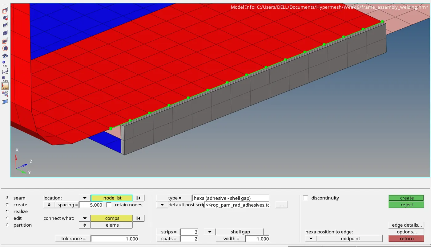
- Hexa (Adhesive): Creates weld connector in as 3D elements (Hexa hedron).
Classifications
Thickness: Thickness is defined by Tolerance. The actual value will be the length between elements to connect.
Width: Width of the Hexa mesh.
Strips: No. of elements along the width.
Coats: No. of elements along with the thickness.
Pic 4:
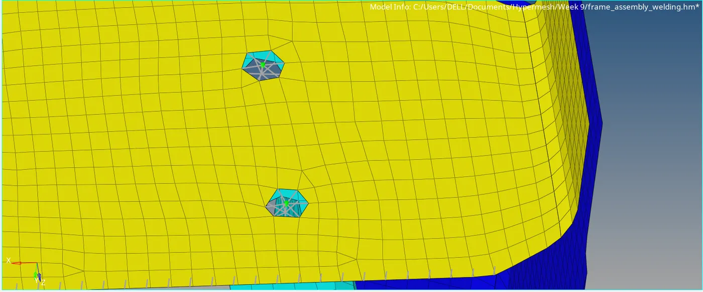
BOLTS: In terms of mechanical, bolt is a temporary connection between 2 or more components. Connection made by Bolt or screw with or without washer.
- Bolt (General): Simple bolt connections made by this option.
Column 1: Locations and No. of components to be connected are filled.
Column 2: Property and Vector is selected.
Column 3: Mesh dependent > Create hole, if none > Adjust hole > Realize and hole detect.
Pic 5:
SPOT: Spot connectors create weld connections at points. (Spot weld)
- Spot (Rigid): Creates 1D rigid elements.
Column 1: Locations (Nodes), Tolerance (Thickness), Connect what (Components/Surfaces) No. of connections.
Column 2: Type (Rigid), material properties, Diameter of the weld.
Column 3: Connector creation method:
Mesh Dependent > Adjust mesh > Quad transition > Imprint.
Pic 6:
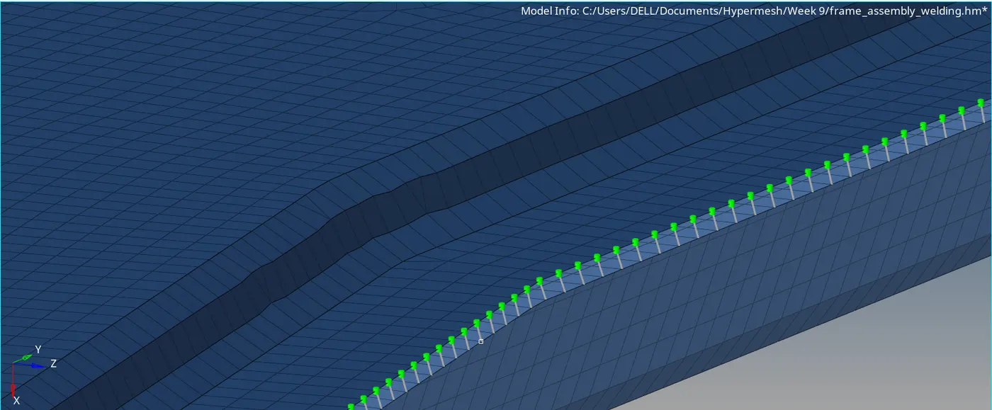
- Spot (Spring): Creates 1D spring elements.
Only parameter changes from spot (rigid) is type. Type will be spring on column 2.
Pic 7:
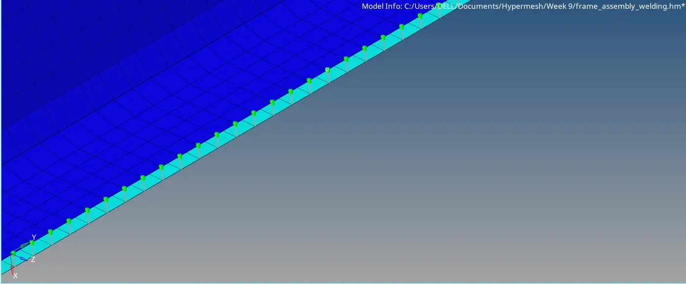
FINAL IMAGES:
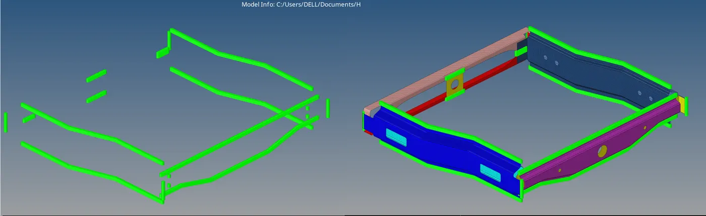
RESULT:
The final mesh created with various connectors like Spot, Seam and Bolt and verified its status.