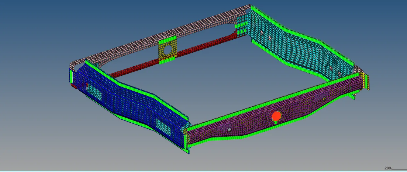
Week 9-Challenge
Objective:
- To create connectors and attach various parts of the given model
- Right_Rail_2 & Front_truss_1:- Seam-Quad(angled+capped+L)
- Left_Rail_2 & Front_truss_1:- Quad elements
- Front_truss_2, Front_truss_1 & Right_Rail_1:- Spot weld with 3 Layers and 5 mm Diameter
- Front_truss_2, Front_truss_1 & Left_Rail_1:- Hexa (Adhesive)
- Rear_truss_2 & Right_Rail_2:- Bolt Connector
- Rear_truss_2 & Left_Rail_2:- Bolt Connector
- Right_Rail_1 & Right_Rail_2:- Spot-weld with Rigid Elements
- Left_Rail_1 & Left_Rail_2:- Spot-weld with Spring Elements
- Rest all the component left Join them with suitable connectors
Case setup and execution:
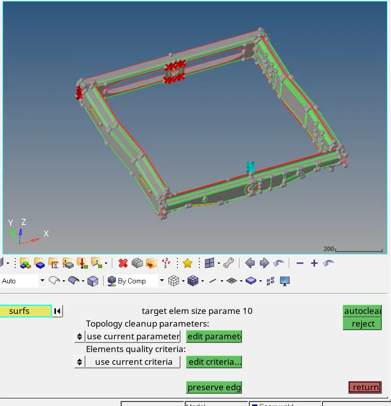
- Geometry cleanup
The given model is imported into Hypermesh. The model consists of many midsurface components.
- Meshing
There are many components in the model, and we will mesh them individually
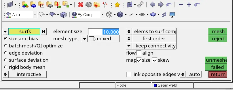
All surfaces are automeshed using 10mm as target length and in the automesh option, flow – align and size are checked
It is better to split the surface into smaller rectangles as much as possible to have smooth quads on the surface.
Geometry -> Quick edit -> Split surface (Node to Node or Node to Line)
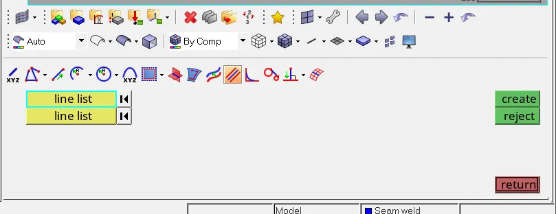
On fillets/hem regions, it is advisable to capture the high points on the fillet. In order to capture the high points, create a Mid line between the boundary lines of the fillet.
Lines -> Midline
Create nodes/points on the Mid Line
Geometry -> Quick Edit -> Add points on Line (Qty:3 – if given 3, two points will be on the endpoints and one will be created on the midpoints of the line)
Geometry -> Nodes -> Interpolate nodes on line (Qty:3)
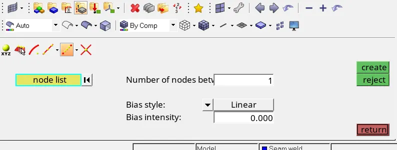
Now we can split the fillet/hem region using
Geometry -> Surface edit -> Trim with free lines and N1,N2,N3 and toggle the boundary lines of the fillet so that mesh quality error due to minimum size criteria can be avoided.
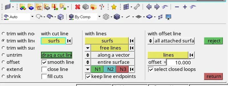
2D -> Automesh
Some of the commonly used commands
Geometry -> Node edit -> Align
2D -> Smooth
2D -> mesh edit -> Split
2D -> mesh edit -> Create
2D -> mesh edit -> combine
Tools -> Reflect
Tools -> Project
These tools are used to make sure the following criteria are satisfied
- No rotational quads
- No trias pointing opposite to each other or touching each other
- Mesh flow is smooth
- No trias on edges of the midsurface
- Elements pass the quality criteria provided
Connectors generation:
All types of connectors are available in
1D/2D/3D -> Connectors
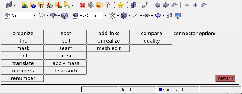
To create a Seam connector,
1D -> connector -> Seam

And use appropriate options
Location: Use lines/nodelist
Spacing: give value equal to element size we specified in automesh
connect what: select the components to be connected
Tolerance: this is the search tolerance. The node will search for other nodes within this search tolerance. Safe to provide a value greater than the distance between the components to be connected
Type: select the type of seam to be used like Quad(angled+capped+L), Quad elements, Hexa(Adhesive)
No postscript
Property: Rigid connectors don’t need any property. Other connector elements need property. We can use the component property or create a new property for connectors
Quad transition is selected to maintain proper flow in mesh
Imprint option is selected: This will imprint the newly created connector elements onto the components. This will distort the mesh to some extent.
Quad(angled+capped+L) requires these parametrs
Weld angle: angle of the seam element
Cap angle: 75 is recommended
Run off angle: 10 is recommended

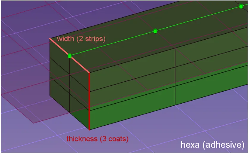
Hexa (adhesive) requires these parametrs
Strips: Define the number of hexa elements required along the width.
Coat: Defines the number of hexa elements required along the thickness.
width: Define the width of the continuous hexa weld in the direction perpendicular to the seam direction.
To create a Spot weld connector,
1D -> connector -> spotweld

And use appropriate options
Location: Use nodes
connect what: select the components to be connected
Tolerance: this is the search tolerance. The node will search for other nodes within this search tolerance. Safe to provide a value greater than the distance between the components to be connected
Num Layer: Total2 for 2 layers of components to be connected
Type: select the type of spotweld to be used like Plot, Rigid, Spring, etc.
No postscript
Property: Rigid connectors don’t need any property. Other connector elements need property. We can use the component property or create a new property for connectors
Diameter: Diameter of spotweld. 5mm is recommended
Project and find nodes: the selected nodes will be projected onto the other component and nodes within search tolerance will be selected for connection
To create a Bolt connector,
1D -> connector -> Bolt

And use appropriate options
Location: select one node in the Hole section of a component
connect what: select the components to be connected
Num Layer: Total2 for 2 layers of components to be connected
Tolerance: this is the search tolerance. The node will search for other nodes within this search tolerance. Safe to provide a value greater than the distance between the components to be connected
Type: select the type of Bolt to be used like Bolt(general), Bolt spider, etc.
No postscript
Property: Rigid connectors don’t need any property. Other connector elements need property. We can use the component property or create a new property for connectors
Consider existing Hole: This option will use the existing hole to create bolt connection. There are other options to create a new Hole and bolt connection.