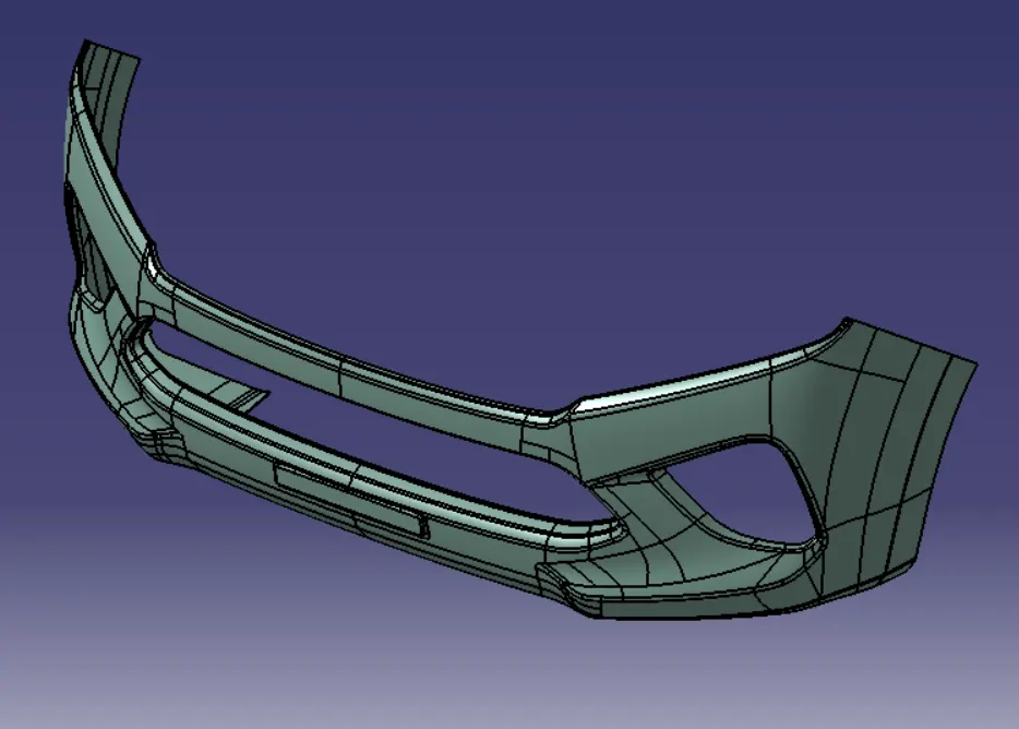
Week 9 - Challenge 3 - Bumper
BUMPER DESIGN
AIM:
Create the bumper plastic component using the given Class-A surface. To begin with, the tooling axis on the given Class-A surface should be created, meeting the requirements of the draft angle, and then the draft analysis on the component.
Objectives:
- To create the bumper plastic component from the given Class-A surface.
- The tooling axis from the given surface must be created to meet the requirement of the draft angle.
- To create the Class-B and Class-C surfaces compared to the Class-A and join the Class-A, B, and C surfaces into a single closed component.
- Perform the Draft Analysis on the model.
INTRODUCTION:
A bumper is a structural component attached to the front and rear ends of a motor vehicle, designed to absorb and mitigate impact in low-speed collisions, thereby protecting passengers, pedestrians, and vital parts of the vehicle such as the engine, trunk, lights, and exhaust system.
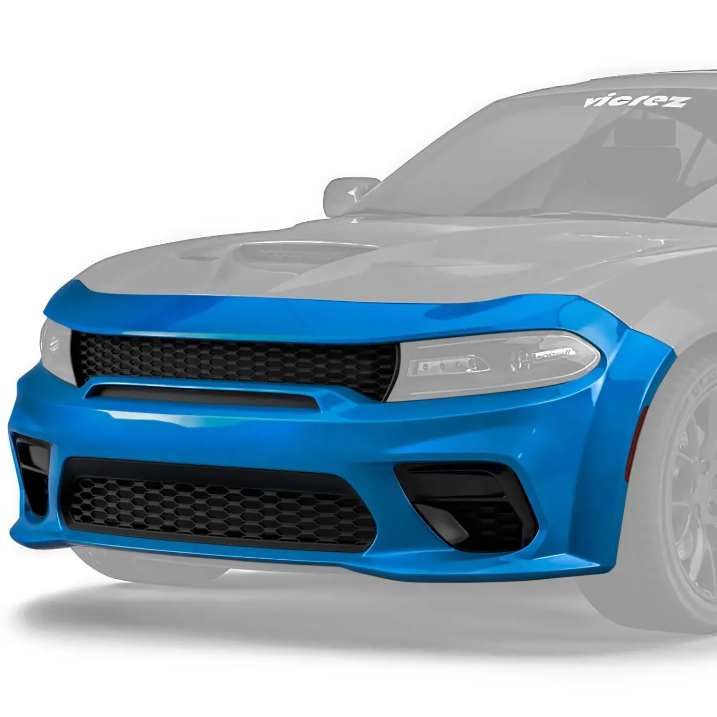
Typically made of plastic covers over a reinforcement bar and energy-absorbing materials like foam or rubber.
Integrated into the vehicle’s body design for both functional and aesthetic purposes.
Regulated by safety standards in many countries to meet impact performance and pedestrian safety requirements.
Functions:
- Impact Absorption – Minimizes damage during low-speed collisions.
- Safety – Helps protect pedestrians and occupants.
- Aesthetic – Integrated into vehicle design for a sleek look.
Types of Car Bumpers:
Standard Bumpers – Made of plastic or metal with energy-absorbing materials inside.
Reinforced Bumpers – Include extra support bars, often used in trucks or off-road vehicles.
Custom/Aftermarket Bumpers – Modified for style, performance, or added protection.
Common Materials:
Thermoplastic or thermoset plastics.
Aluminum or steel (especially for internal reinforcement).
Polypropylene foam or similar for impact absorption.
CLASS-A SURFACE:
Class A is an aesthetic finish with the highest quality. Most Class A surfaces for automotive components are created using Autodesk Alias based on final concept sketches. All Class A surfaces must have "curvature continuity." That is, continuity between surfaces must have the same boundaries. It is used as a reference for automotive plastics designers to create "Class B" and "Class C" finishes.
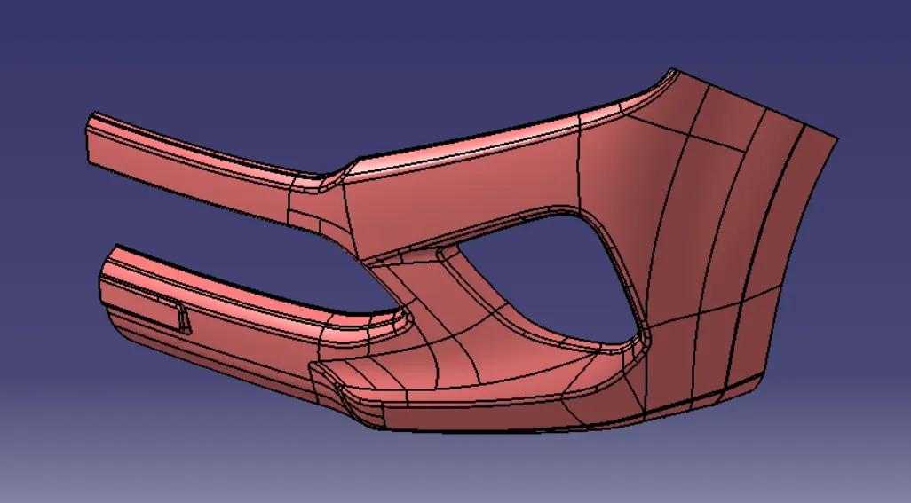
TOOLING AXIS:
The tooling axis defines the direction in which a mold or core and cavity open during the molding process. It's essentially the direction of the molded part's "pull" or "draft" away from the mold. To define the tooling axis, you typically need to identify a point and a direction or create a line representing the tooling direction.
This axis is crucial for draft analysis and plastic component design.
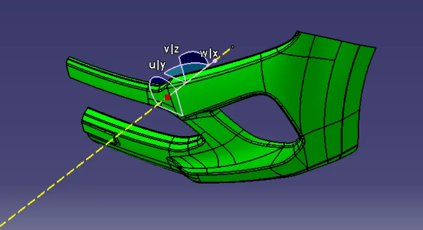
The Tooling Axis is created from the X Direction on the Class A surface:
- The center point is created using the point on the selected curve.
- At this point, the axis system is created
- After pointing to the surface to draw a line, the line is created from the point to the X Direction.
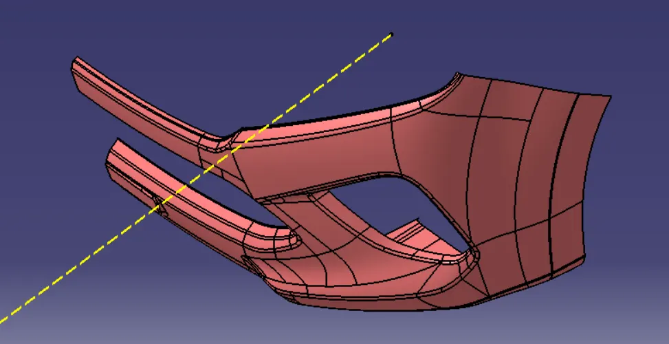
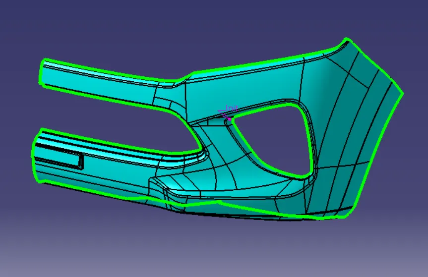
CLASS-B SURFACE:
A class B surface is below a class A surface at a certain thickness. It is created using structural principles consisting of all necessary features such as ribs, bosses, and snaps. This surface is invisible to an outside observer.
Creating Class-B Surface:
- Offset the class-a surface to 3mm(thickness)
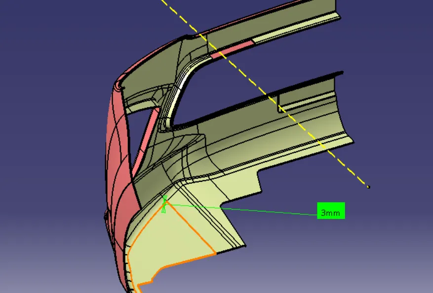
- Fill the patches that are not offset using the commands Extract, Boundary, multi-section surface, Extrapolation, Trim, and Edge fillet.
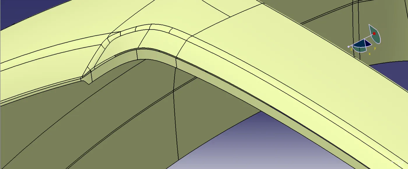
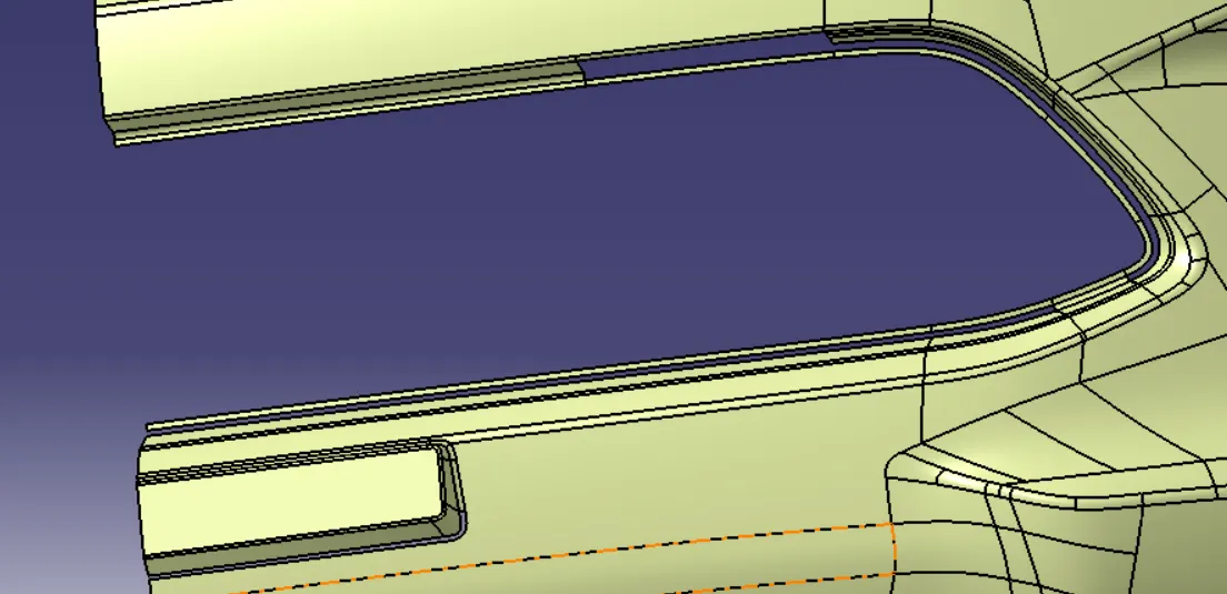
- Then join the patches to the offseted surface using the join command.
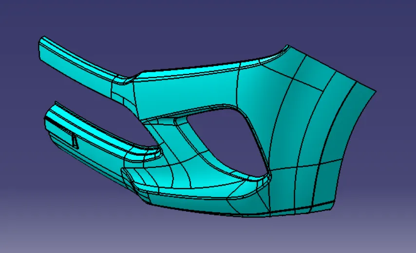
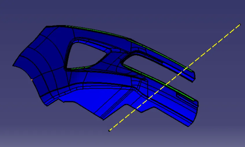
- To check the final surface using the boundary
CLASS-C SURFACE:
A class C surface is a surface created to connect class A and class B surfaces.
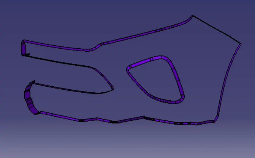
- Join all the surfaces (Class-A, B, and C)
- Create a Closed body surface in part design.
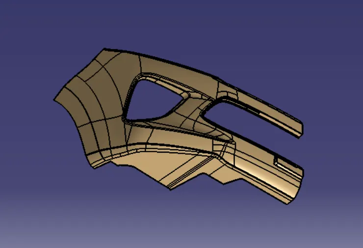
Close Body:
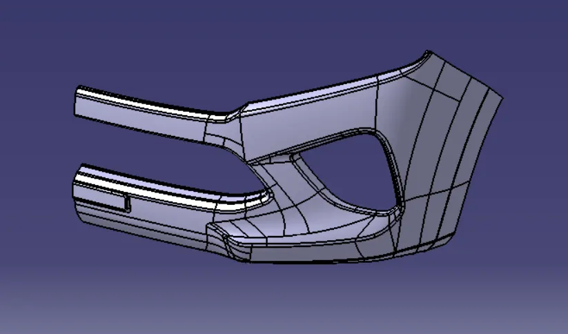
DRAFT ANALYSIS:
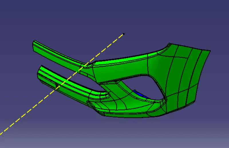
Draft analysis enables you to detect that the part we drafted will be easily removed. This type of analysis is performed based on color ranges, identifying the zones on the analyzed element where the deviation from the draft direction at any point corresponds to specified values.
- Go to insert
- Click on the compass icon and align it with the tooling axis, and click on the surface. We will get our result.
Class-A Draft Analysis:
Final Body Draft Analysis:
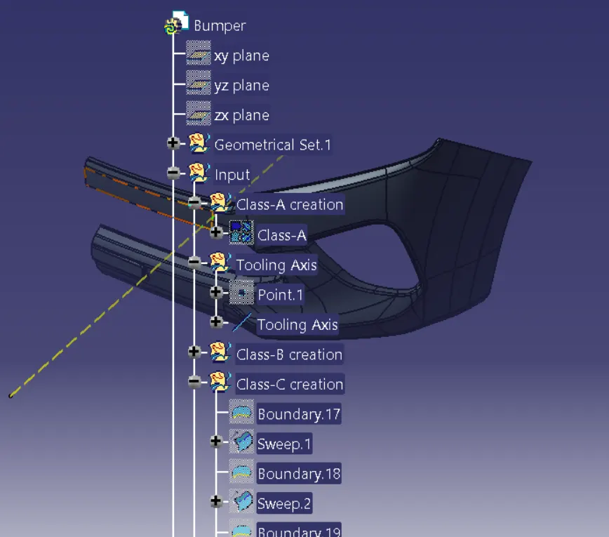
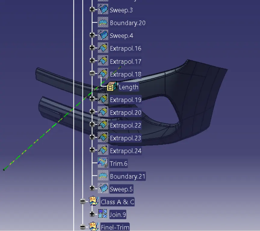
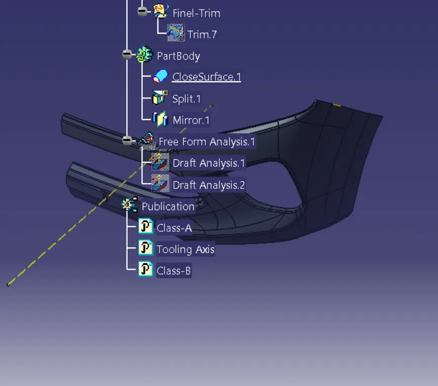
Tree Structure:
Orientations:
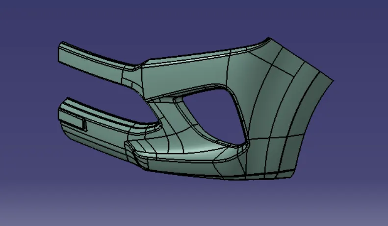
Isometric View:
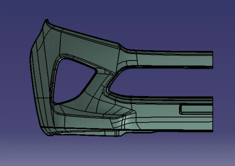
Front View:
Side View:
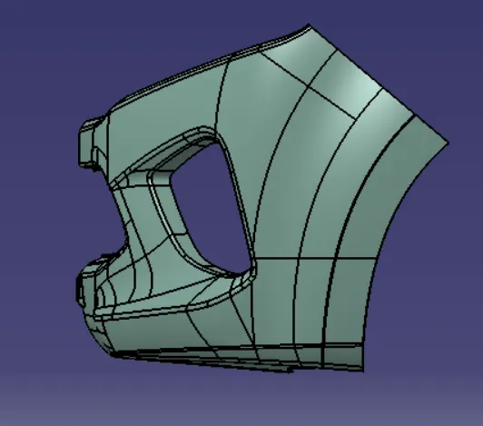
Top View:
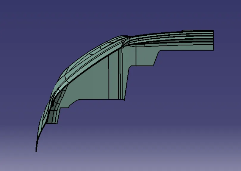
Bumper :