Week 9 - Challenge 3 - Bumper
Object :- Create a tooling axis in proper way for finding better draft analysis from given class A surface. Create draft analysis of class A surface and create class B and class C surface from class A surface. And finally create draft analysis of finished body.
Consider the thickness of the component 3 mm.
Introduction :- This project is done on CATIA software. This software is different from other. It is easy to designing for surface modelling. Its have more accuracy than other.
Class A Surface :-
In automotive design application Class A Surfaces are created on all visible exterior surfaces (ex; body panels, bumper, grill, lights etc.) and all visible surfaces of see-touch & feel parts in interior (ex: Dashboard, seats, door pads etc.). This can also include beauty covers in the engine compartment, mud flaps, trunk panels and carpeting.
Tooling Axis :-
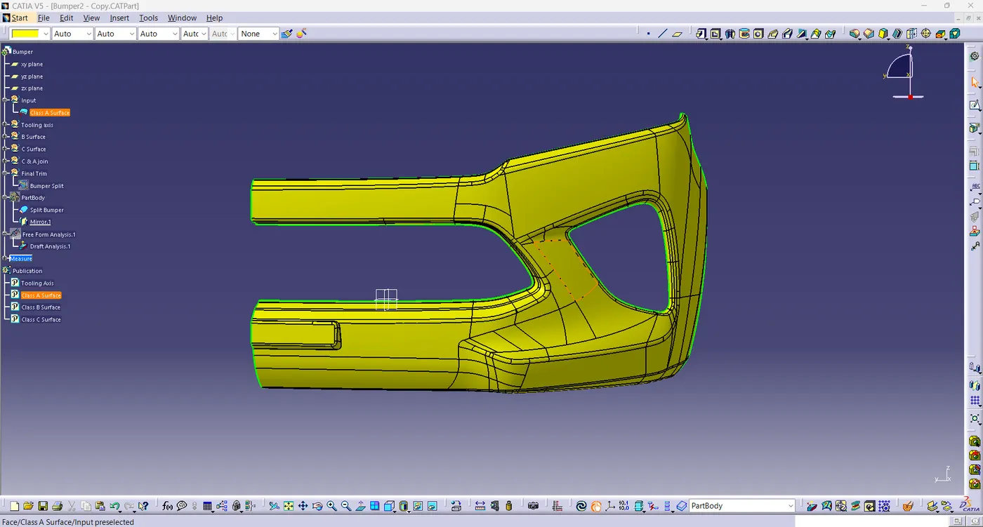
Tooling axis or tooling direction is main consideration for plastic part and mold parts because it defines movement of mold part and possibility of plastic part to come-out from mold part (Core and Cavity). In Molding machine arrangement is given to open the mold along a direction which is known as Tooling Direction. The mold is built from two separate halves (Core and Cavity) and tooling direction basically define the direction of mold pulls apart. Tooling direction is known as primary direction.
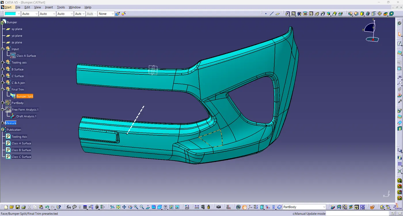
- Here I have created a tooling axis. First of all I extract a base surface and create a mid pont on it. And then I create a line through this point with perpendicular to base surface. And then I performed draft analysis ans I saw every thing is ok. Then finally it is my tooling axis.
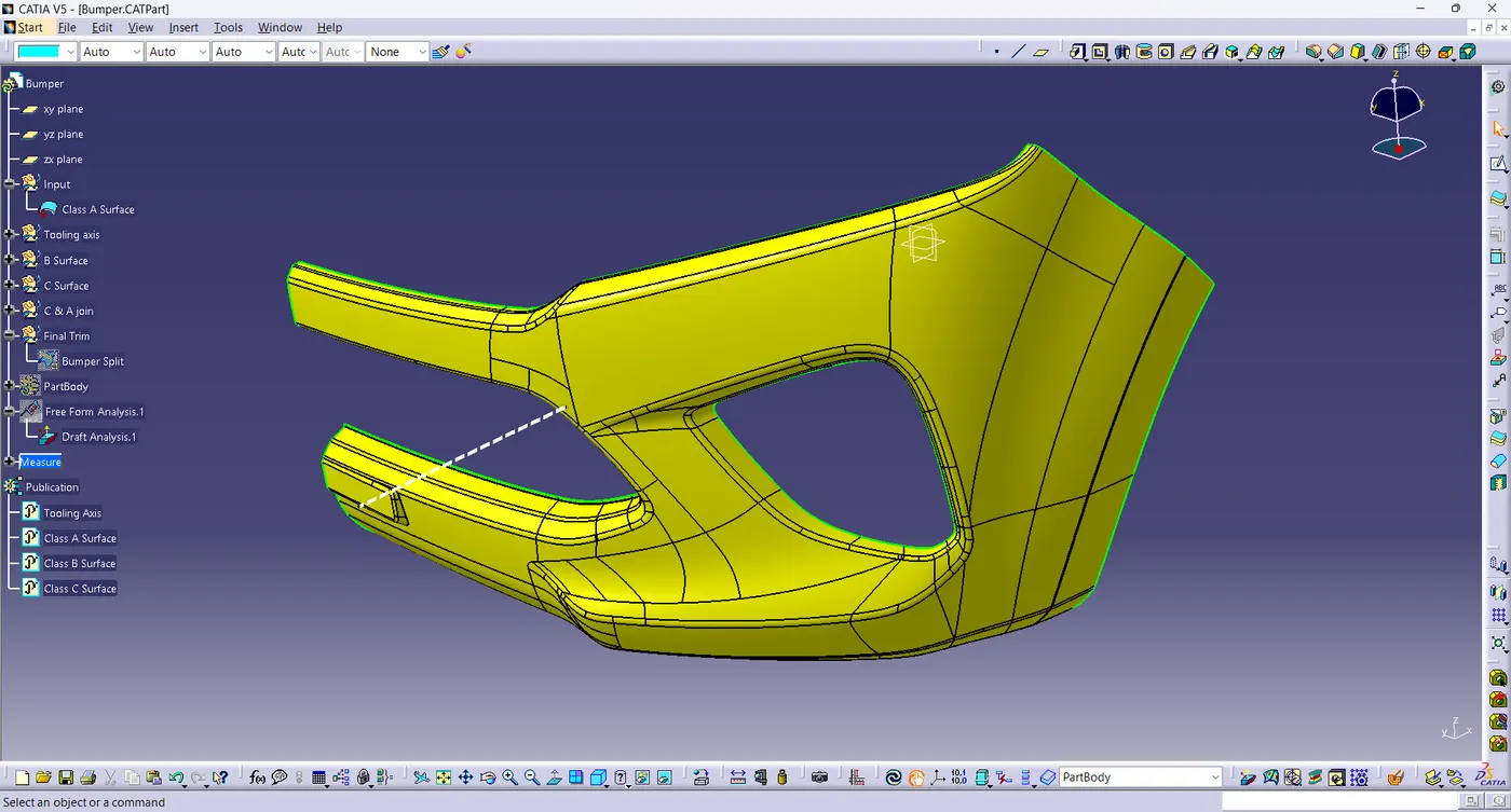
-
Class B Surface :- The surface which is back side of Class A surface is called Class B Surface. Mostly it not visible. It is created with the help of Class A surface with some distance (thickness) like 2mm, 3mm etc.
- Here I created Class B Surface on 3mm from Class A Surface.
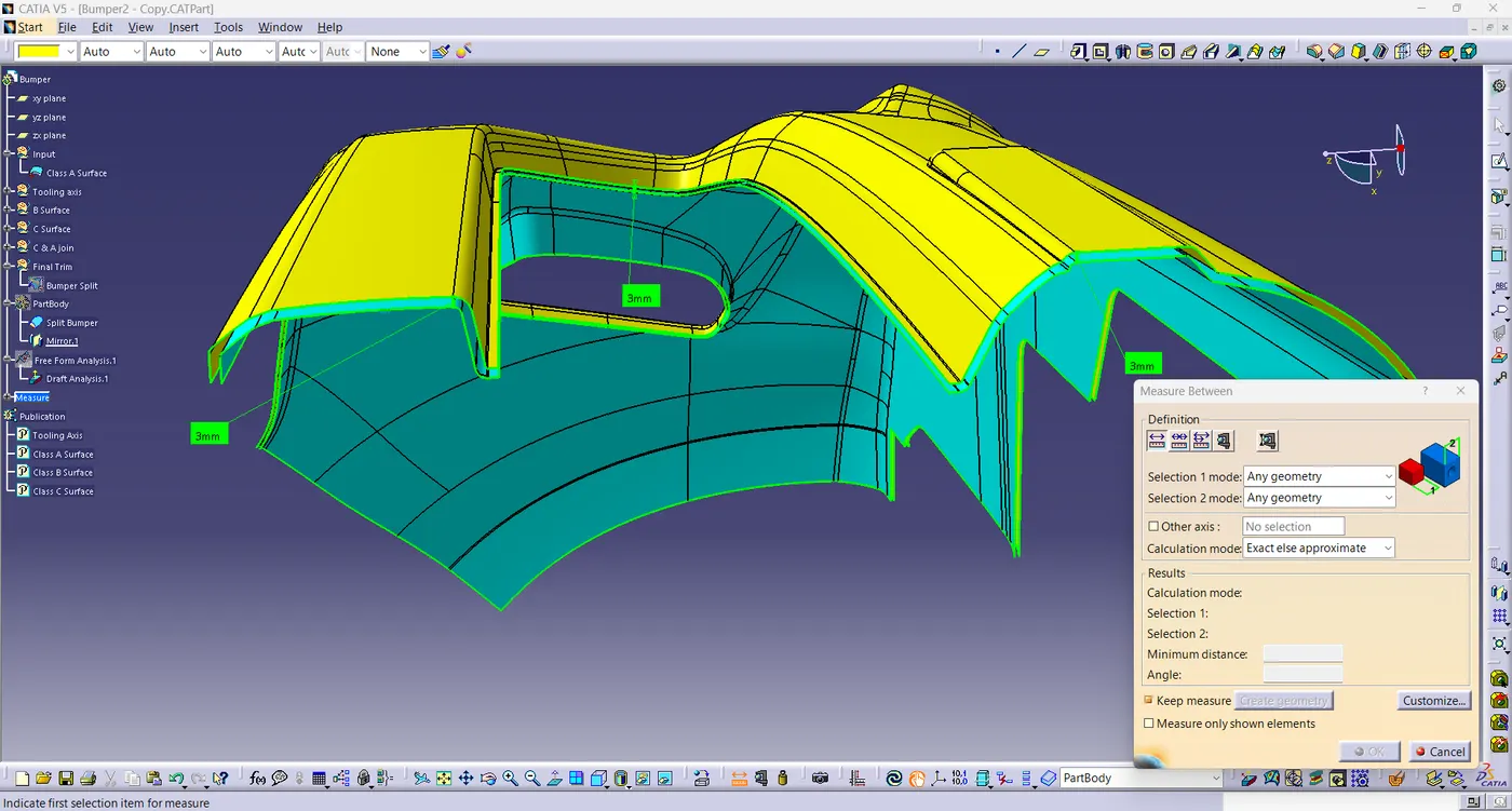
- Class C Surface :- The Class C surface is the back side of a part of a surface that is permanently covered by another part.
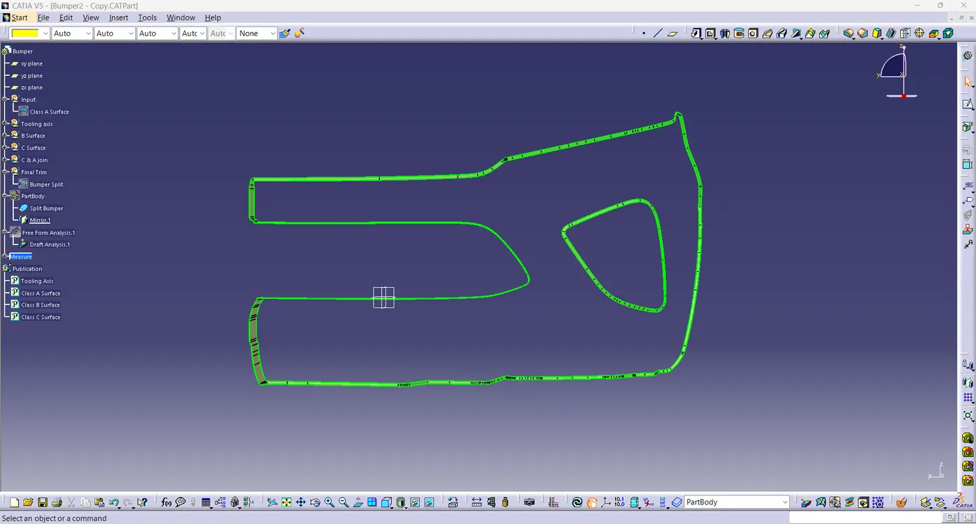
- With the help of join and trim feature I have created a closed surface body.
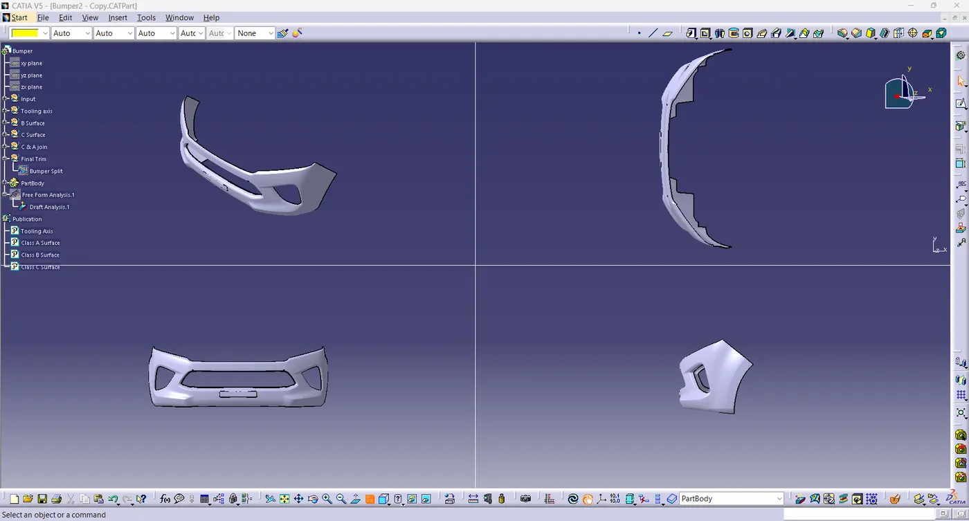
Draft Analysis of Part Body :-
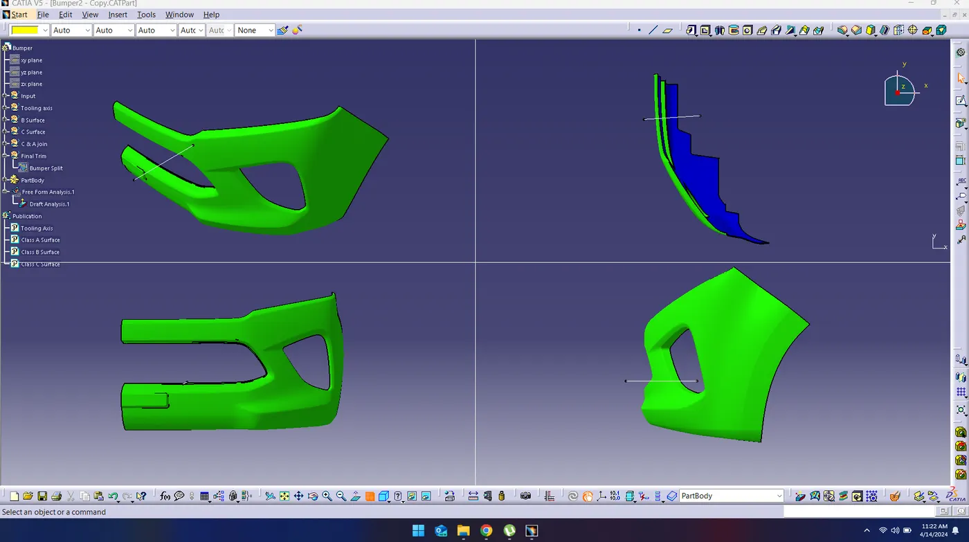
Conclusion :- In this project we learnt that how to find tooling axis in appropriate way and how to create Class B and Class C Surface from Class A Surface.