Week 9 - Challenge 3 - Bumper
OBJECTIVE:
The objective of this project is to create the Bumper component of the Automobile with the help of the provided Class A surface. The complete creation of Class B and Class C surfaces along with the tooling axis creation and draft analysis is performed on the component.
GIVEN DATA:
The Class A surface data is provided.
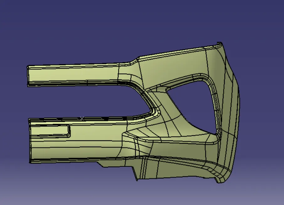
Also, the thickness of the component is taken as 3mm.
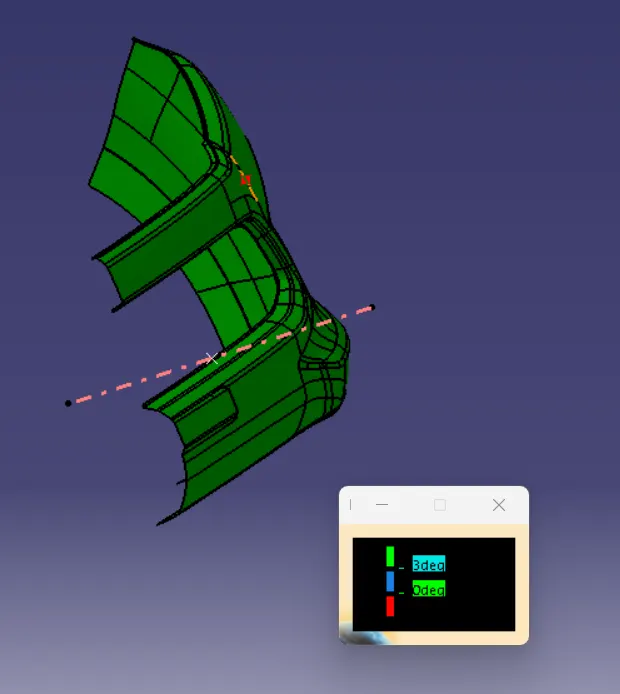
We begin the process with the creation of the tooling axis. From visual inspection, we can visualize all the components with respect to the X-axis. Therefore we create a dummy tooling axis along the X axis on any curve suitable and perform the draft analysis.
We can see that the component's draft analysis along the dummy tooling axis clears the 3-degree draft angle criteria. Therefore we fixed the dummy tooling axis as our main tooling axis.
Here a bisecting angle case hasn't arisen, so we directly go with the dummy tooling axis.
As we succeeded in the creation of the tooling axis, we moved on to the creation of a proper Class B surface.
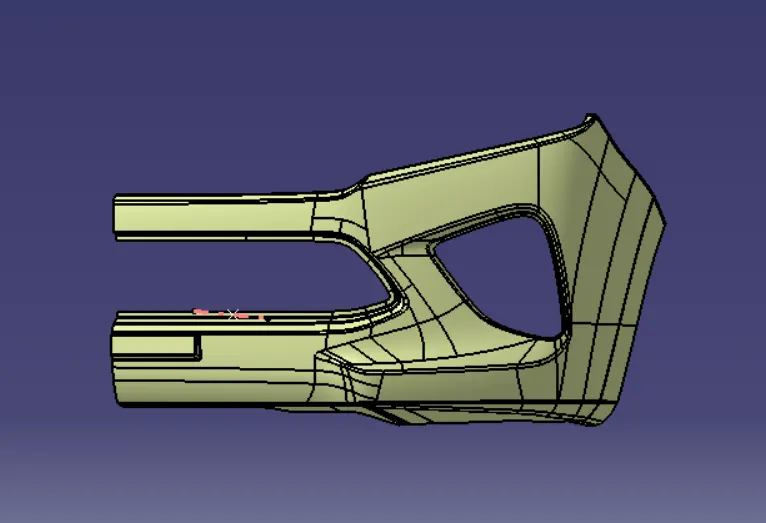
The Class A surface has a complex structure. Therefore we adopt a different strategy than going for the normal extraction and extrapolation method. We directly offset the whole surface to 3mm and the work on critical sections and points.
With missing fillet patches, we create extraction surfaces with sharp corners and apply the required fillet altogether. We also perform different extract, untrim, and extrapolation operations to obtain the required Class B surface.
Now for the creation of the C surface, we use the sweep command.
But clearly, the parting surfaces are oriented in different directions.
Also parting surface should not lie on the Class A as it can cause obstructions to the aesthetic appearance of the component.
For edges that extrapolate parallel to the tooling axis, we can blindly provide a draft angle of 90 degrees. But for surfaces perpendicular to the tooling axis, there is a 3-degree draft angle provided.
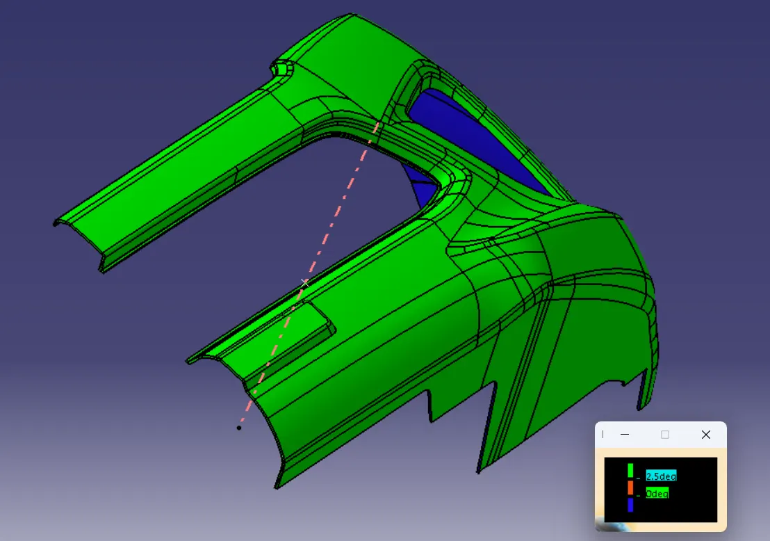
Using proper intersection and trimming, the complete Class C surface is obtained. Then we perform a final trim to obtain the bumper sections. After checking for any present boundaries inside the body, we proceed to the part design workbench, and using the close surface command we create a solid bumper component.
We also successfully completed the draft analysis on the solid component with a 2.5-degree draft.
Additional screenshots of tree structure and geometrical sets are provided below.
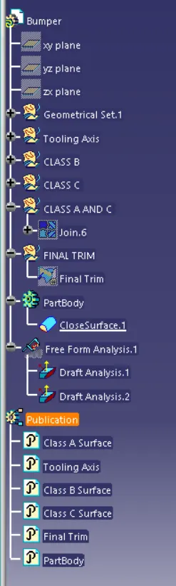
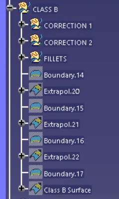
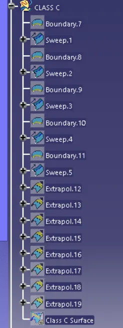
The complete part file is also attached below.
RESULT:
Successfully created Tooling Axis, Class B, and Class C surfaces and draft analysis separately done on Class A and final product with respect to the created tooling axis.