Hood design-Week 2
HOOD DESIGN [ PERFORMED ON NX 12 ]
OBJECTIVE: Design the Hood Outer Panel, Inner Panel, and the necessary Reinforcements in reference to the Master section provided.
INTRODUCTION:
The hinged cover above the engine of a car is called the Hood. Opening of hoods provides access to the engine compartment mainly for maintenance and service purposes.
From a design standpoint, the hood must satisfy a number of requirements, including those related to pedestrian safety, lock striker positioning, force distribution in the event of a frontal accident, safety of passengers, etc.
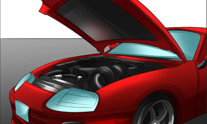
Fig 1: Representation of an Automobile Hood
Hood outer and inner panels, latch and striker, hinge, and hood stay make up a conventional hood assembly.
A mechanism known as a hood release is present in most automobiles. It typically consists of an inner hood latch or lock handle, a cable to open the hood, and a lock that closes the hood. The hood lock handle is typically found in the door frame on the opposite side of the driver's seat or, less frequently, on the same side as the steering wheel. When the engine hood is opened, the engine room may be inspected, cooling water and engine oil can be refilled, parts can be changed, repairs can be made, etc.
A hood stay is a device that holds the open engine hood of an automobile in place. They can be of 2 types: simple support rods or more complex gas stays.
Car hoods are often built of steel and aluminum, though they can also be made of other materials. In addition to dry carbon, carbon fiber, and fiberglass, a wide range of alternative materials can be used to make aftermarket automobile hoods.
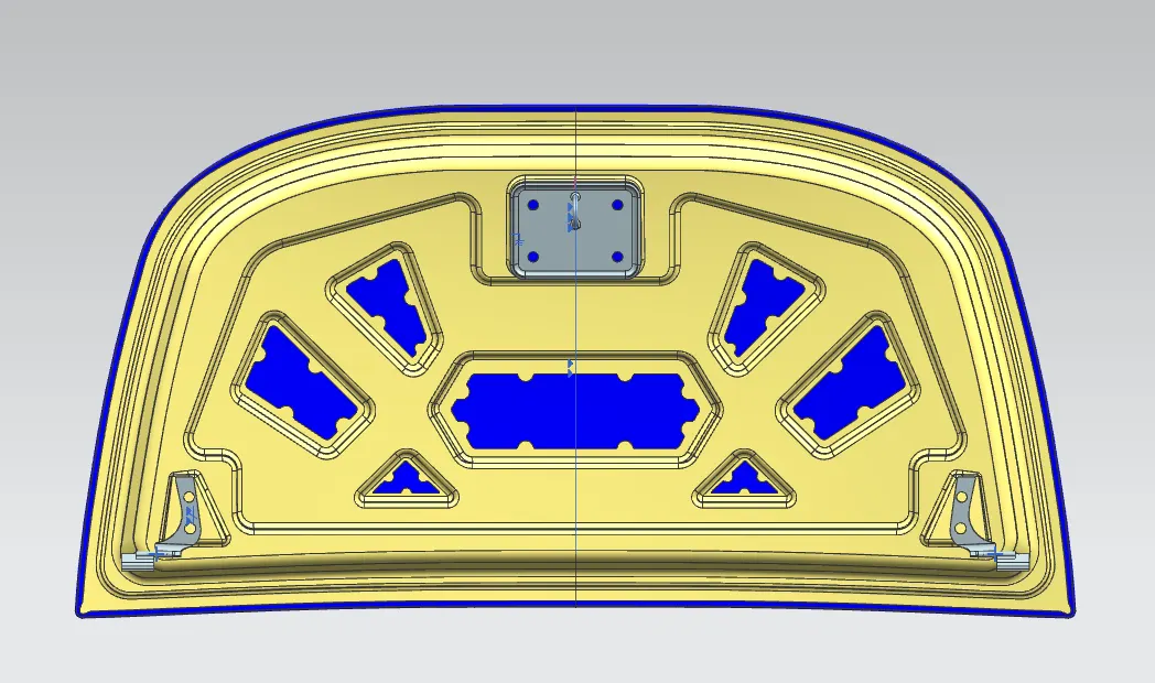
Fig 2: Complete Assembly of a Hood
DESIGN PROCESS:
The master Section provided is given below:
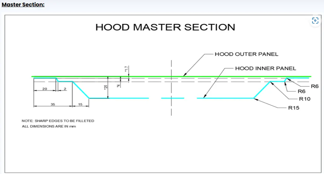
Fig 3: Master Section
Hood Outer Panel:
We start the design process from the given skin data of the Outer panel. The outer panel should be designed primarily on pedestrian safety considerations and also on the engine compartment capacity, not to mention the aesthetic appearance of the hood. Hemming is used to join the outer panel to the inner panel. Therefore, the requisite hemming flange and reliefs must be provided for the hemming operation. To lessen vibration, we also offer mastic sealants between the outer and interior panels.
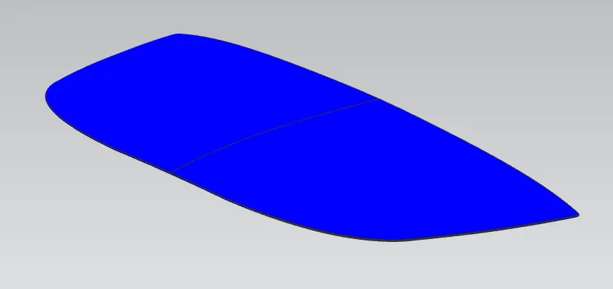
Fig 4: Hood Outer panel from Skin data
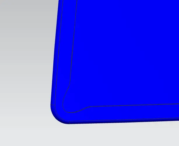
Fig 5: End Reliefs provided for Hemming.
Hood inner panel:
The inner panel provides strength and rigidity to the outer panel. The initial emboss size and shape are represented by the master section. After determining the placement, we then supply the emboss for the latch and hinge components. The further reinforcements, mastic data, etc. all are attached to the inner panel.
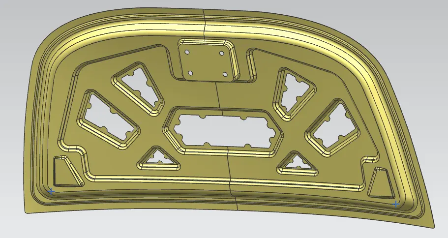
Fig 6: Hood Inner Panel
Striker and Hinge along with Reinforcements:
A sensor near the front of an automobile that detects contact with an object is part of a system for opening and lifting the hood. The hinge operates upon a circular trajectory that ensures a smooth opening of the hood. To strengthen the regions where an attachment is provided, such as a striker or hinge, we add reinforcements. Reinforcements typically have a thickness that is more than that of the inner panels, and their value varies depending on cost and demand.
The hinge and latch reinforcements are given a 1.5mm thickness here in accordance with the design specification. Also while creating embossed we try to create it in such a way that it creates stress concentration points you to adhere to passenger safety.
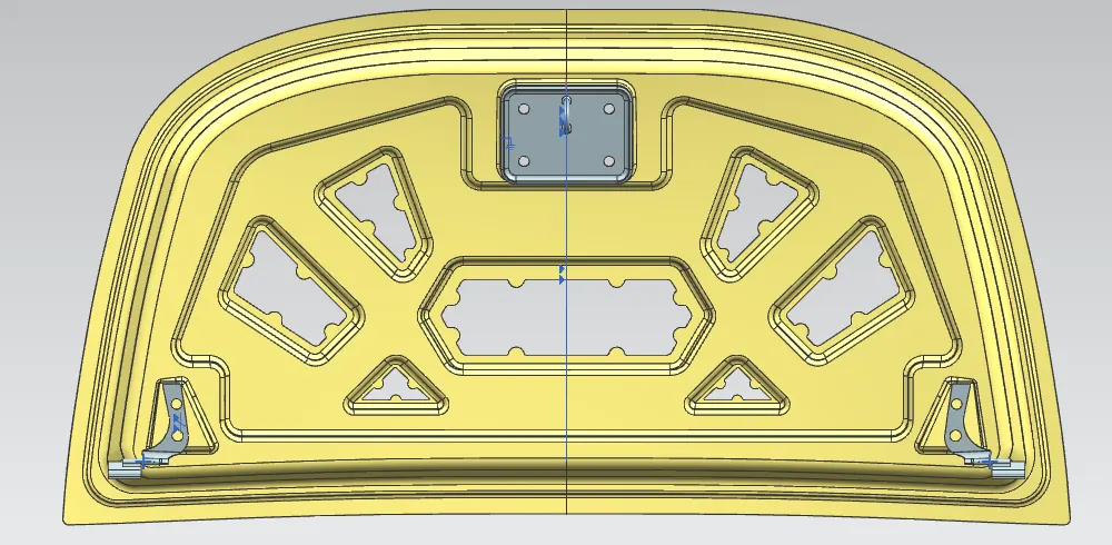
Fig 7: Striker and Hinge in Grey.
Latch Trajectory:
The circle formed by the hinge axis point provides the latch trajectory. Either the latch or the hinge can be fixed first. If the hinge location has been fixed, the trajectory circle for the latch should be plotted. The striker axis through the tip of the striker should be tangential to the latch trajectory for optimum mating conditions.
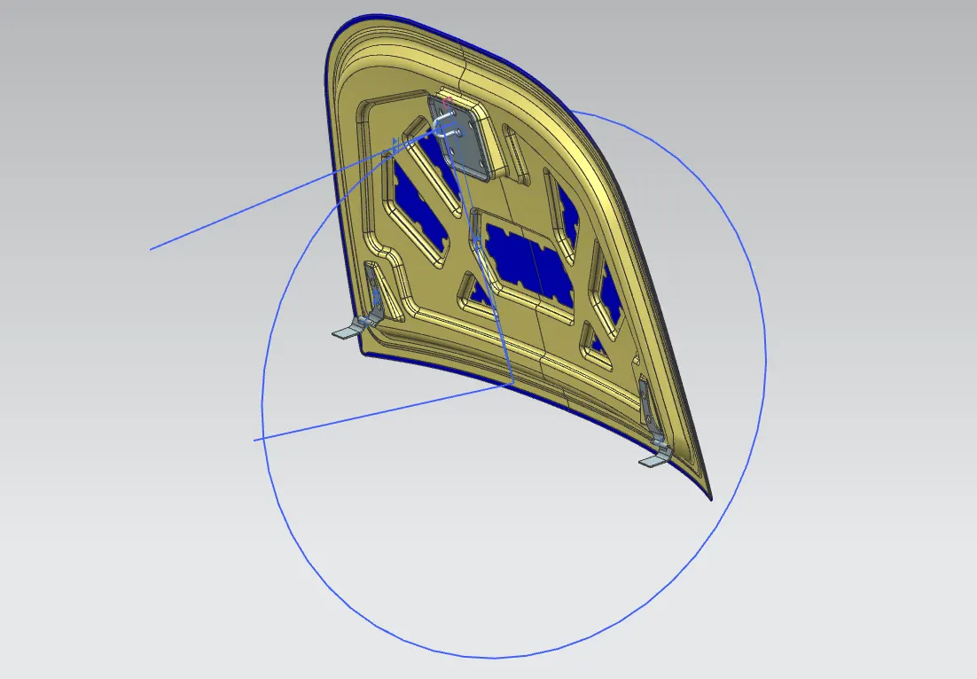
Fig 8: Latch Trajectory
Mastic Data:
Hoods frequently have enormous surfaces, and the only way to hem one of them is through the boundary. Other joining methods, like welding and riveting, produce traces on the outside panel that detract from its visual appeal, thus we are unable to use them. Therefore, the inner surfaces of the outer panel and inner panel are adhered to using mastic sealants. Mastic sealants are rubber-like elastic compounds. At predetermined locations, it is applied between the inner and outer panels. Each mastic sealant area has an 80mm diameter sphere that it affects. As a result, the mastic points are positioned so that they cover the more vibration-sensitive parts away from the hemming.
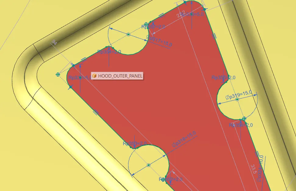
Fig 9: Mastic Data Definition
Emboss Definitions:
The inside panel features a variety of embosses. These embosses enable us to increase the inner panel's rigidity. The size and shape of the embosses also affect how the force distribution from a frontal collision is distributed. Always distribute the force away from the passengers. Based on each designer's calculations numerous emboss definitions can be made. I have made the following emboss definitions in the project.
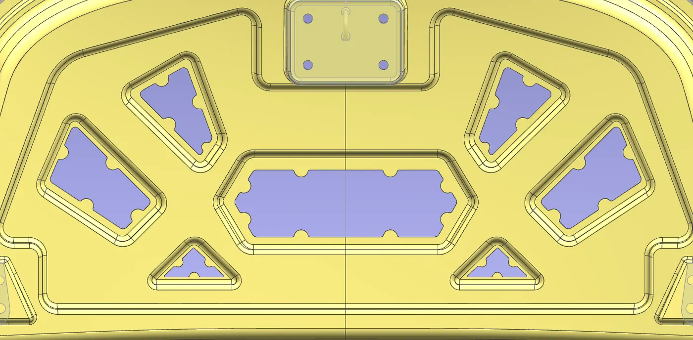
Fig 10: Emboss Definitions
The manufacturing processes mainly used in the hood design are Deep Drawing and Hemming which are discussed below.
Hemming :
In order to obtain a tight fit, the sheet's edges are folded or folded over another area during the hemming process. Hemming procedures are typically used to join components together, to enhance a part's appearance, and to reinforce part edges.
Hemming is a secondary technique used in the assembly of automotive parts to link two sheet metal sections (the outer and inner) together after deep drawing, trimming, and flanging operations. For this kind of assembly, hoods, doors, trunk lids, and fenders are typical components.
There are various types of hemming operations:
- Conventional die hemming
- Roll hemming
Die hemming is used in mass production. In die hemming, a hemming tool is used to fold the flange over the entire length. After the drawing and trimming activities are finished, the flange is created with a hemming tool, which results in the actual hemming of the material. The created flange is subsequently hemmed in a number of processes. These phases comprise, for instance, the pre-hemming and final hemming based on the flange's respective opening angle. Although conventional die-hemming production facilities are quite expensive, they have relatively quick cycle times.
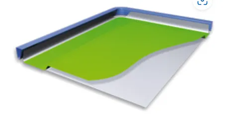
Fig 11: Die Hemming
In Roll Hemming, a hemming roller is used to hem rolls progressively. The flange is formed and the hemming roller is guided by an industrial robot. Several pre-hemming and final hemming process processes can also be separated into the roll hemming operation. When compared to traditional die hemming, roll hemming offers much greater tool flexibility and cheaper tool costs. The fact that the hemming is accomplished with a hemming roller that follows a predetermined path, however, results in substantially longer cycle times.
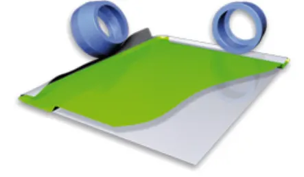
Fig 12: Roll Hemming
Deep Drawing:
The transformation of a sheet metal blank into cylindrical containers with a flat or hemispherical base is known as deep drawing. When the drawn part's depth is more than its diameter, the procedure is referred to as "deep" drawing. This is accomplished by redrawing the component using a number of dies. Due to the material retention property, the flange region experiences radial drawing stress and tangential compressive stress. It basically consists of a die, punch, and blank holders. The mechanical impact of a punch causes a sheet metal blank to be radially dragged into a forming die. Thus, it is a shape-change process that keeps the material. Flange wrinkles are caused by these compressive forces. By using a blank holder, which facilitates controlled material flow into the die radius, wrinkles can be avoided. It combines sheet metal processing with metal shaping.
In Hood Design Deep Drawing is done in the tooling direction which is shown below.
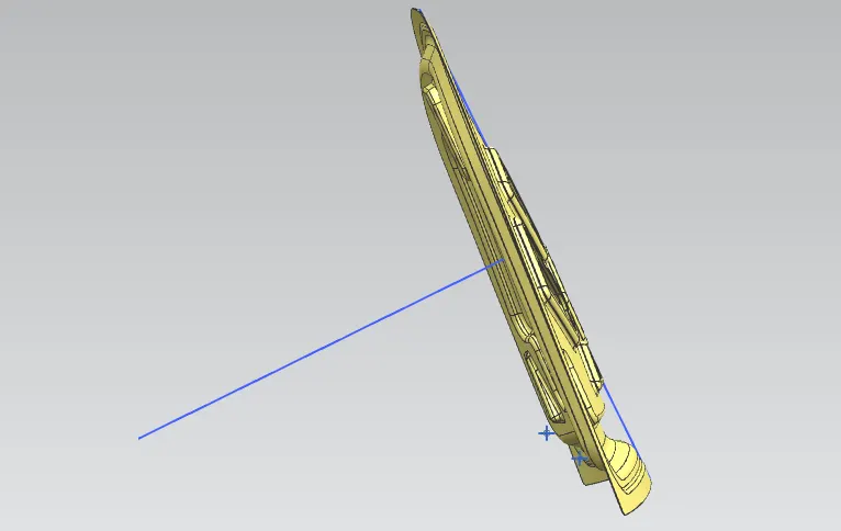
Fig 13: Tooling Direction
This results in the Final Assembly:
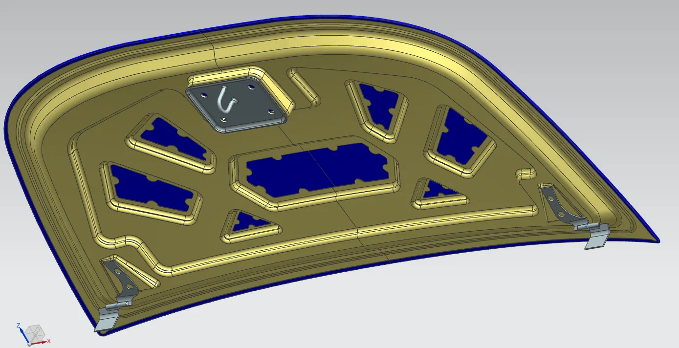
Fig 14: Final Assembly
The design parameters followed are completely in accordance with the master sections and skin data given and,
Hood Thickness Information
Outer Panel Thickness = 0.75mm
Inner Panel Thickness = 0.75mm
Reinforcement Thickness = 1.5mm.