Week 9 - Challenge 3 - Bumper
BUMPER DESIGN
A bumper is a structure attached to or integrated with the front and rear ends of a automobile, to absorb impact in a minor collision, ideally minimizing repair costs.
They are designed to absorb impact onto the front and rear of vehicles and minimize low-speed collision damage. Today, standard passenger's vehicle bumpers have a rigid reinforcing bar under the outer cover, with sections of compressible foam or plastic underneath.
Modern consumer production cars have almost completely switched over to plastic bumpers. Modern car bumpers are made from thermoplastic olefins, a blend of plastic molecules, rubber, and a reinforcing filler like carbon fiber or calcium carbonate. This blend of materials creates a scratch and impact-resistant plastic that can bond with a wide range of paints and finishes, making it ideal for vehicle bumpers.
Plastic is the preferred material for modern car bumpers for several reasons. First and foremost, plastic is much lighter and more aerodynamic than metal, which improves the car's fuel efficiency. Plastic is also easier to shape, which is useful during both the manufacturing and bumper repair process.
Bumpers of most modern automobiles have been made of a combination of polycarbonate (PC) and acrylonitrile butadiene styrene (ABS) called PC/ABS.
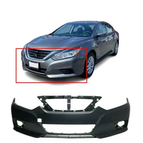
Class A Surface
Class A Surface is the asthetic surface with the highest quality finish that is created through scaning of clay model. This Class a Surface is a input CAD model for part design.All Class A surfaces should have Curvature-Continuity which means the continuity between the surfaces should share the same boundary. It is taken as a reference by the Automotive Plastic Designer to create Class B and Class C Surfaces.
Class B surface
Class B surface is created in a certain distance according to the thickness of the part.It is created using Engineering Principles that consist of all the necessary features such as Ribs, Bosses, Snaps, etc. This surface isn't visible to the observer from the outside.
Class C Surface
The Class C Surface is the surface created between the Class A and Class B surfaces to join them with each other.
PROCEDURE TO CREATE THE TOOLING AXIS:
There are two different methods that we can use to create the Main Tooling Axis for our Class A Surface.
1. Using a Vertex to create a line along the axis which allows us to view all the holes & exposes a maximum surface area of the Class A Surface.
2. Using Inertia Method to find out the Center of Gravity and create a line along it.
First, we'll view the Class A Surface from all three axes to determine the most suitable axis along which the Main Tooling Axis can be created.
A) VIEW ALONG THE Z-AXIS:
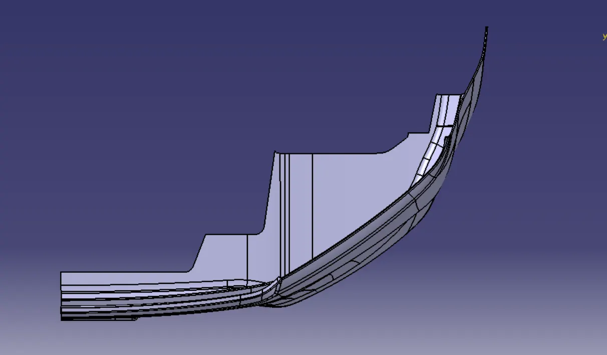
From the above image, we can observe that not much area of the bumper is exposed here and we cannot view either the hole section, not the cutout section from this viewpoint hence this will not be the appropriate direction for the Main Tooling Axis.
B) VIEW ALONG THE Y-AXIS:
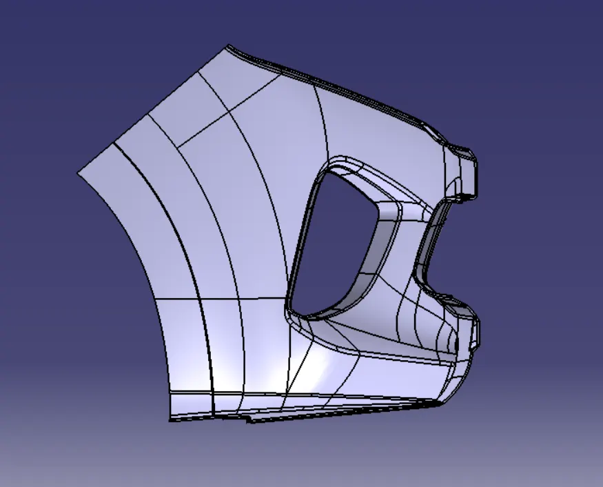
From the above image, we can observe that although more area is exposed along this axis compared to the previous axis it is not sufficient as it'll be difficult to create the hole section and the cutout section from this direction.
C) VIEW ALONG THE X-AXIS:
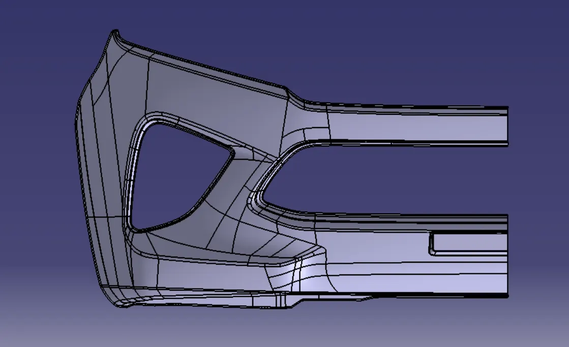
From the above image, we can observe that here the maximum amount of the bumper's surface area is exposed and we can view both the hole section & the cut-out section of the bumper concurrently hence making this direction the most suitable choice for the Main Tooling Axis.
TOOLING AXIS:
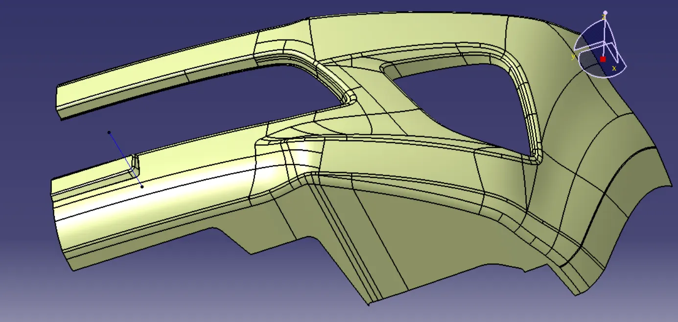
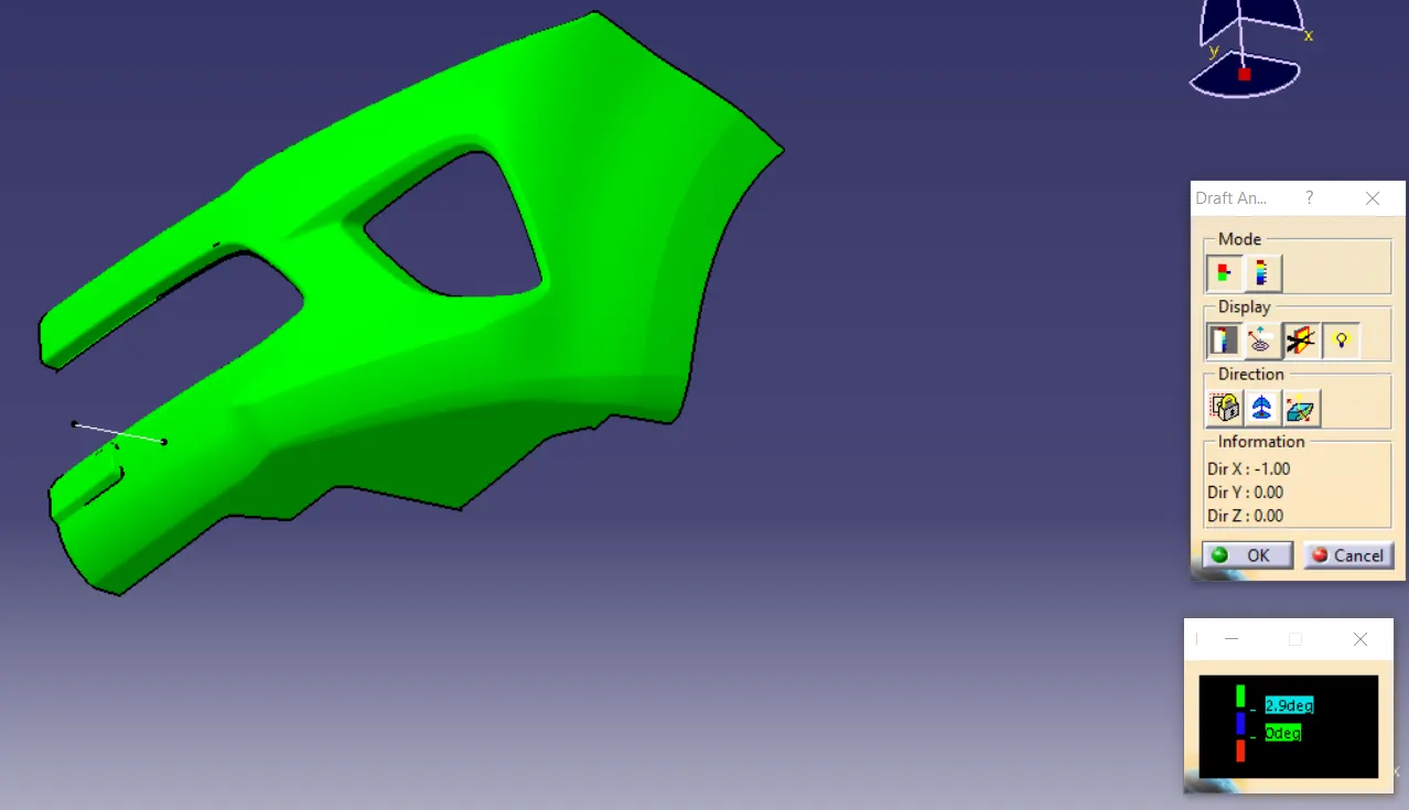
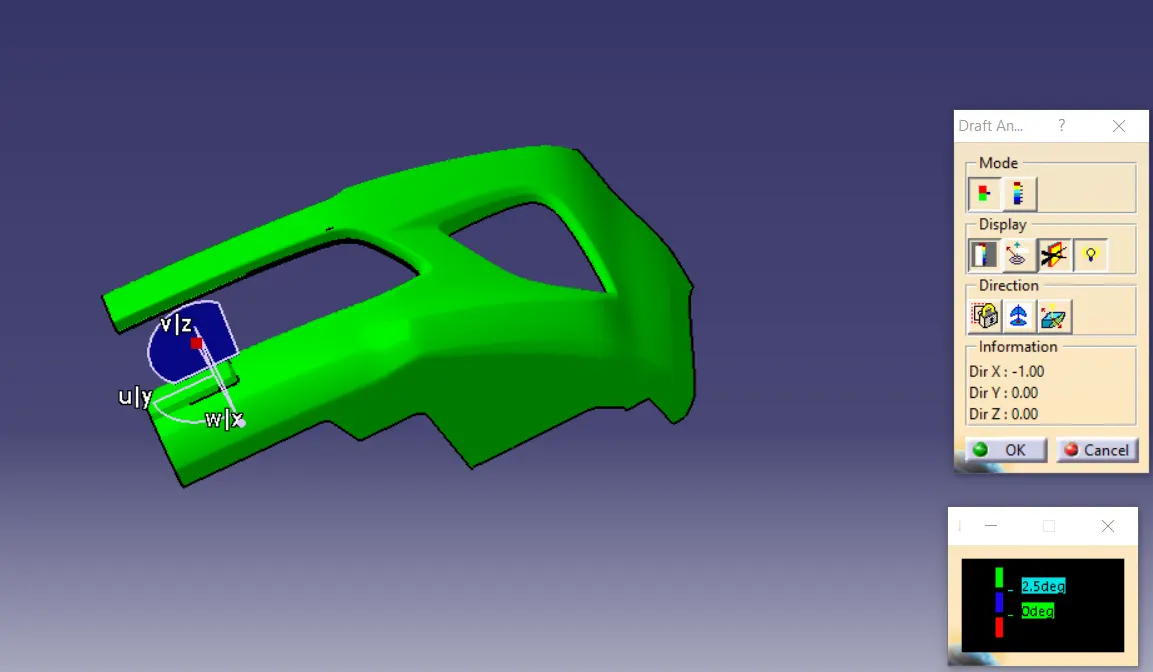
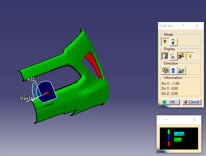
To create the tooling axis, I extracted a surface from class A and created a point in the middle of the surface by using the point command and created a line at that point through the x-axis. Now, I performed a draft analysis check from that line whether the created tooling axis is in the correct position or not. If, in the draft analysis check the surface highlighted with green colour on both sides of the surface the tooling axis is in the correct position and direction.
Draft Analysis
CLASS B SURFACE:
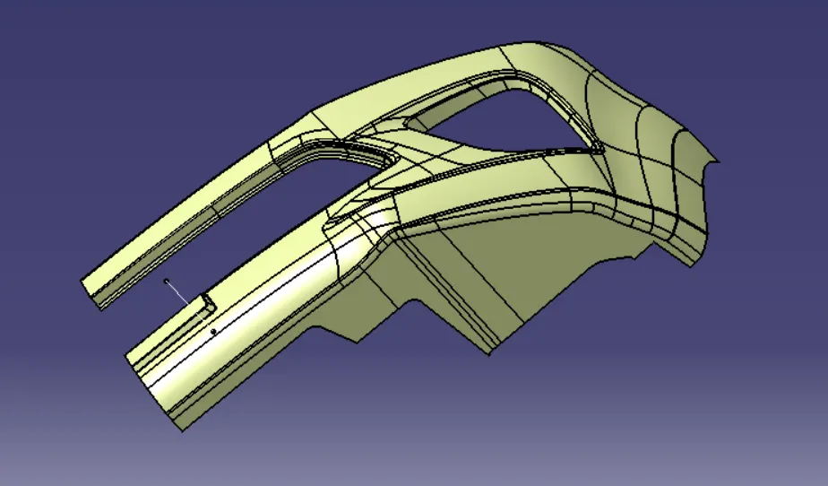
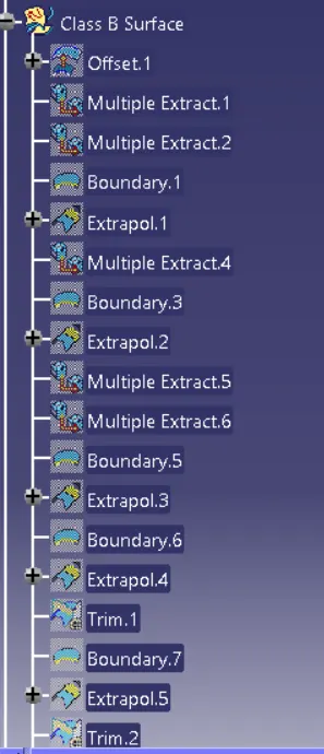
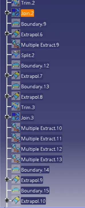
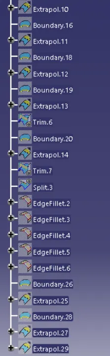
To create the class B surface, offset the class A surface inside as per our thickness requirement (here the thickness is 3mm, so I offset the class A to 3mm inside). Once the offset is created, we can observe some patches on the offset surface by taking the boundary for the offset surface, those patches are formed due to the fillets on the class A surface. We need to cover those patches with the help of the multi-section surfaces command by extracting the patch boundaries. Once all the patches on the offset are covered properly join all the patches with the offset surface, to get the replicated surface of the class A surface.
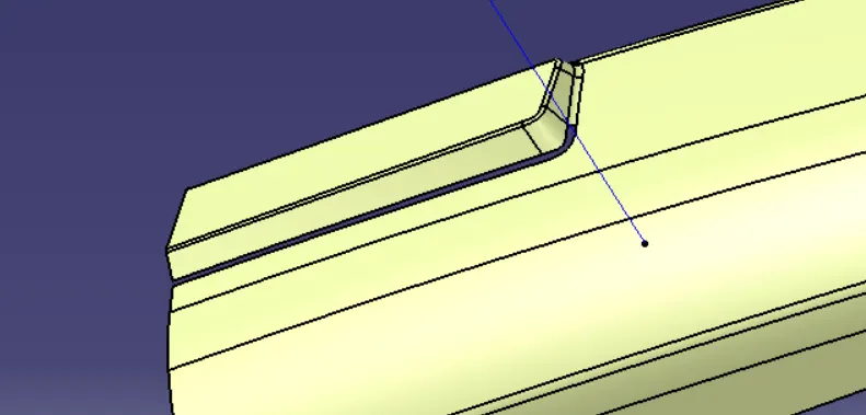
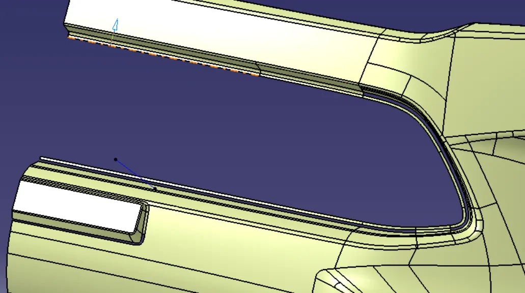
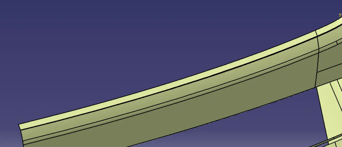
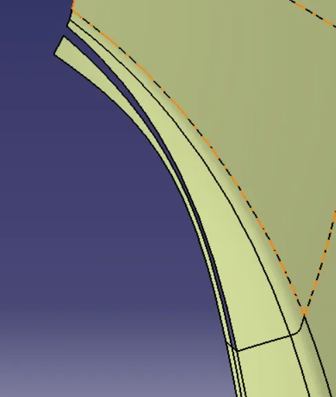
Final CLASS B surface.
CLASS C SURFACE:
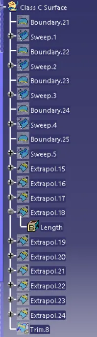
To create the class C surface concerning the boundary of the class A surface, I used the sweep command. Initially, I extracted the boundary of the class A surface with tangent continuity, and I sweep the extracted boundary concerning the surface at 3deg (for draft angle).Once we sweep all the surface boundaries of class A, extrapolate the sweeped surfaces until both surfaces got intersected properly, and trim them to remove extended extrapolated surfaces to get a proper sweep boundary throughout the entire surface, including the centre hole of the bumper.
Now, join both class A and sweep boundary to get the complete class C surface.
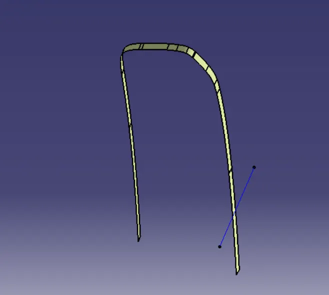
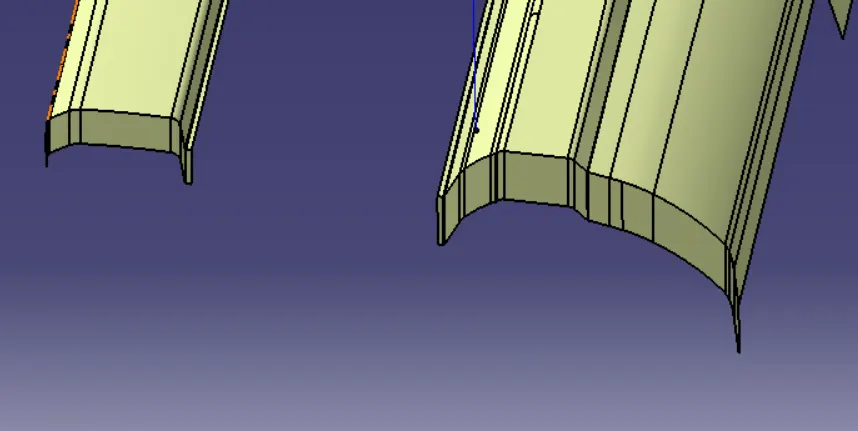
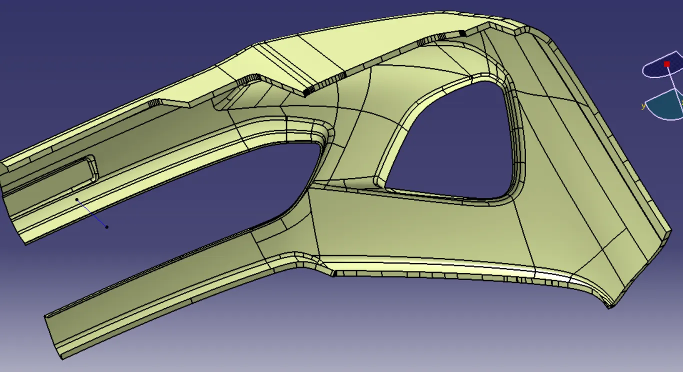
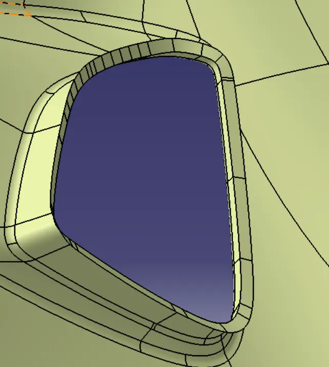
Now, unhide the class B and class C surfaces. Check whether all the sides of class B and Class C surfaces are intersecting properly with each other, to get a closed surface by trimming class B and class C surfaces. If the class B and class C sides are not intersected properly, we need to extrapolate the sides of the class B surface which are not intersecting with the class C surface. Now, check class B and class C surface boundaries whether all the sides are intersecting or not with each other. Once the surfaces are intersecting properly trim them together to get a closed surface.
Final CLASS C surface.
Trim all the Class C surface to join all the sweep to form a surface.
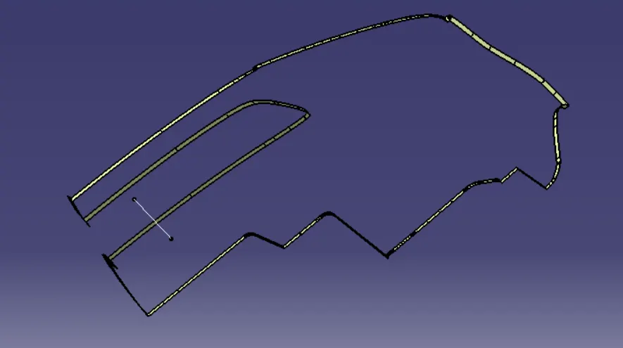
JOIN A & C SURFACE
By using join option we are join the Class A surface with Class C surface
FINAL TRIM
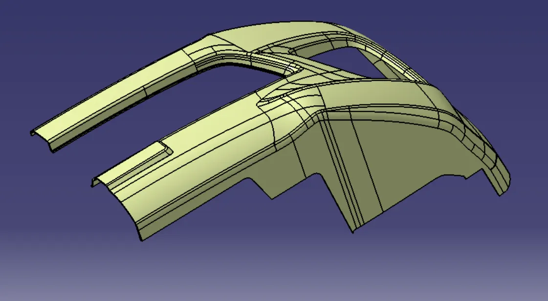
It is the trimming option of Class A&C with Class B surface to join the both surface to form closed surface
PART BODY:
To create the solid part body from the closed surface, I used the closed surface command in the part workbench.

DRAFT ANALYSIS:
After creating a solid body from the closed surface I performed a draft analysis on it, to check the draft angle of the solid body.
Draft angles are a required feature of injection-molded custom parts. A functional part for injection molding has to have draft angles that face both the cavity and core sides. This will reduce the risk of damage to the parts and ensure that they can be ejected from the machine.
TREE STRUCTURE :
Conclusion
The Draft analysis of the component showed that the component is feasible to be molded without any issues.
Thus it satisfies all design and manufacturing criterias needed for a proper part.