Week 9 - Challenge 3 - Bumper
BUMPER
AIM
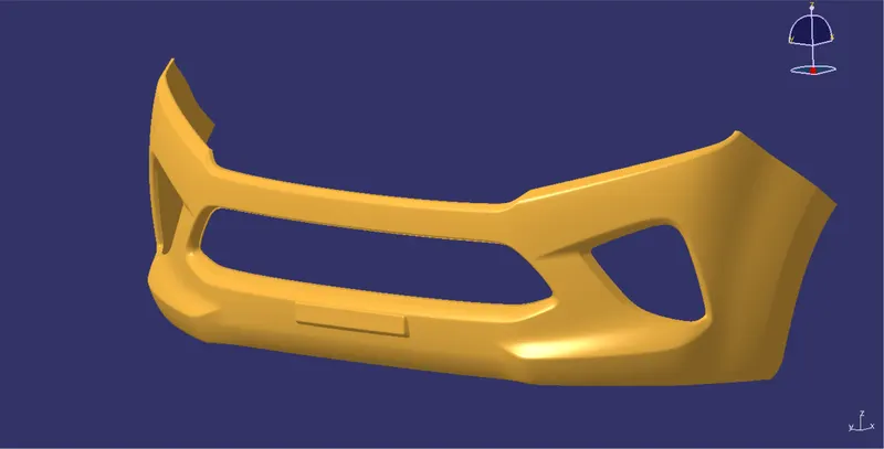
- Create the Bumper Plastic component through the given Class-A surface. To begin with, the tooling axis for the given Class-A Surface.
INTRODUCTION
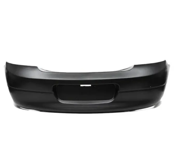
- A bumper is the curved bar across the front of a car that protects it from getting dented or scratched during minor accidents. If you bump into your mailbox, you may damage your car's bumper.
OBJECTIVE
- To design Bumper as per automotive industry Standard.
- Create tooling axis for the given CLASS-A surface.
- Create B and C Class surfaces.
- Create final surface model and convert it into solid body.
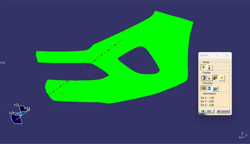
- Perform draft analysis for both Class-A surface and Final part body.
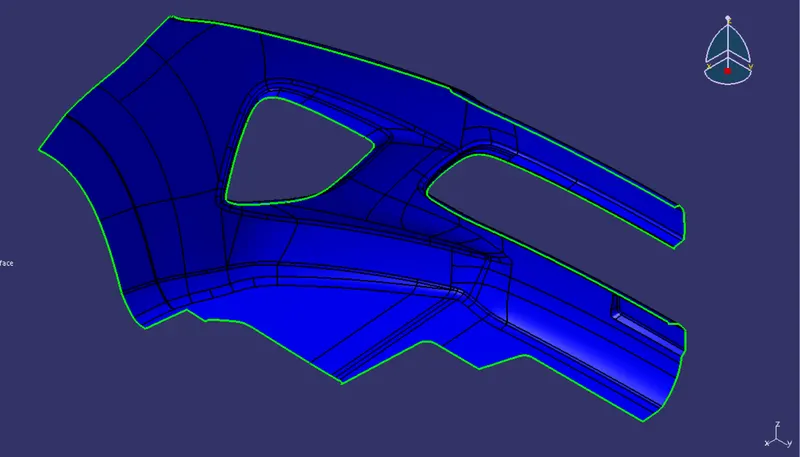
Class A is
1.Visible surface and aesthetic look
2.surface with textures
3.Surfaces provided by customer(OEM)
4.Don't have any features like(rib, snap, bosses, etc) on class A surface.
5.Class A surface is made from scanned data with different software like alias etc.
6.Surfaces which are having CURVATURE CONTINUITY IS CALLED class-A.
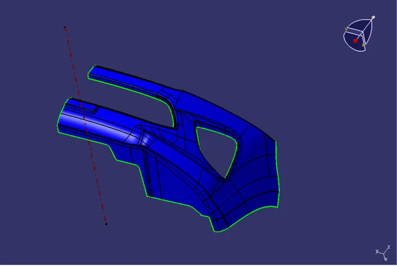
TOOLING AXIS
- Tooling axis represents the opening and closing of the mold core and cavity during the manufacturing of the components. A plastic product designer should consider the best tooling direction to cutdown the cost of the component very less.
DRAFT ANALYSIS
-
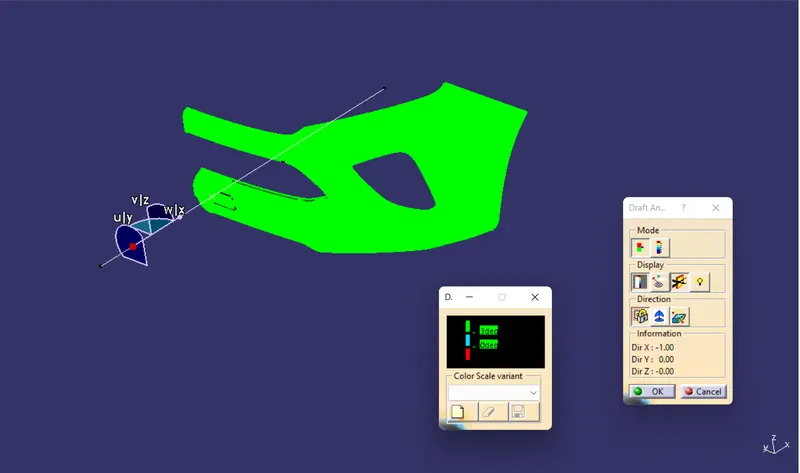
The Draft Analysis is a command enables you to detect if the part you drafted will be easily removed. This type of analysis is performed based on colour ranges identifying zones on the analysed element where the deviation from the draft direction at any point, corresponds to specified values.
-
Draft analysis is done after determining the tooling axis, draft analysis is used to check whether the minimum draft (3 degrees) is maintained or not.
Check Draft Analysis for the given Class A surface
CLASS B SURFACE
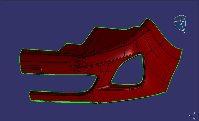
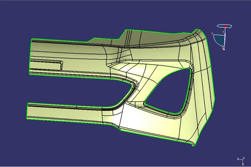
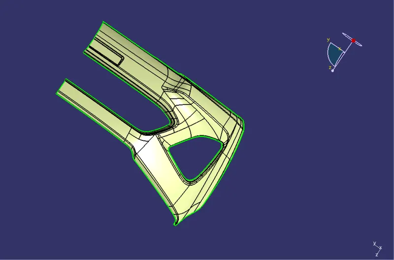
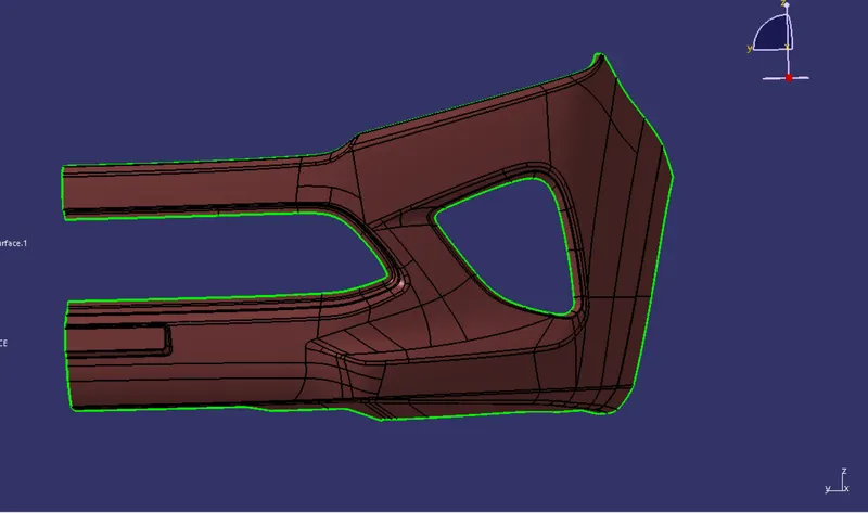
- A surface below a certain thickness from the class-A surface is class-B surface. This is the surface that contains engineering aspects of a model.
Class B Surface is created in different steps:
1. OFFSET
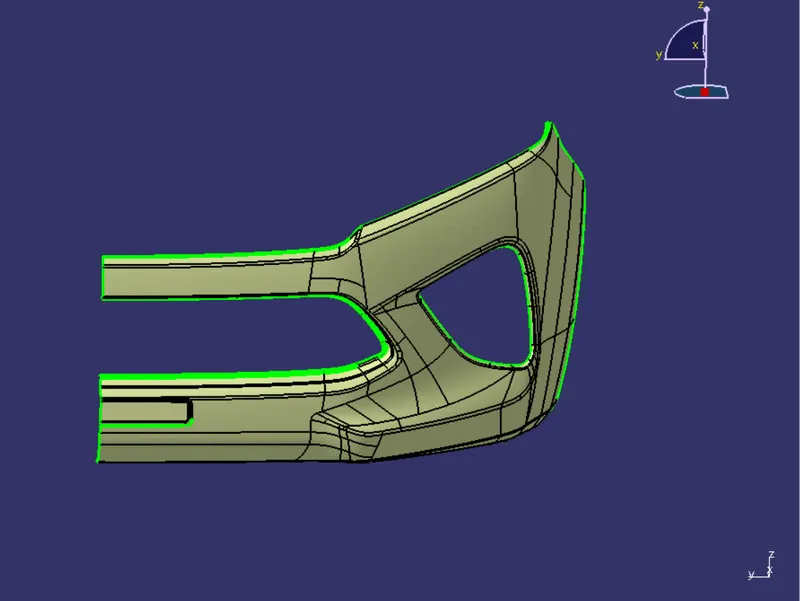
2. PATCH 1
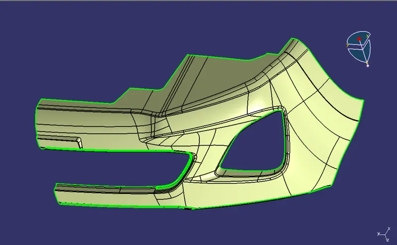
3. PATCH 2
4. PATCH 3
5. FILLET
6. FINAL CLASS B SURFACE
CLASS C SURFACE
-
Surface that joins class-A and class-B surfaces is class-C surface. Class C is often specified for interior surfaces not readily visible, surfaces that will be covered by another part when assembled
-
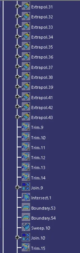
Since it is a complex class-A surface, we cannot simply create the class-A boundary curve and sweep it at one shot. Hence, we need to create smaller curves using multi-extract command and then create sweep of 90 degree with reference to the surface option. sweeps at the midportion of the bumper should have a 93 degree vaue to pass the draft analysis.
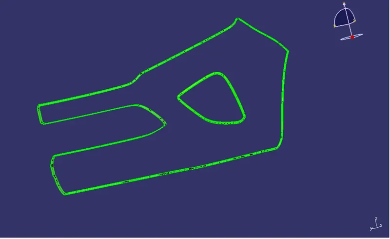
FINAL OUTPUT
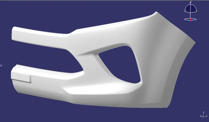
SOLID MODEL OF A BUMPER
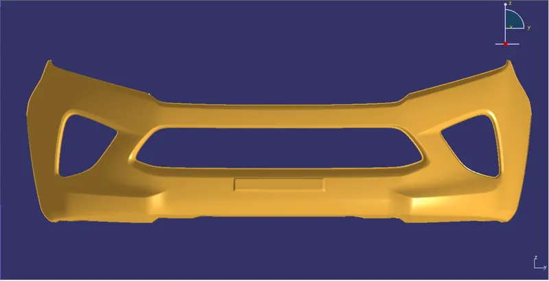
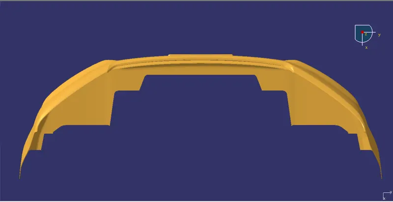
FINAL DRAFT ANALYSIS
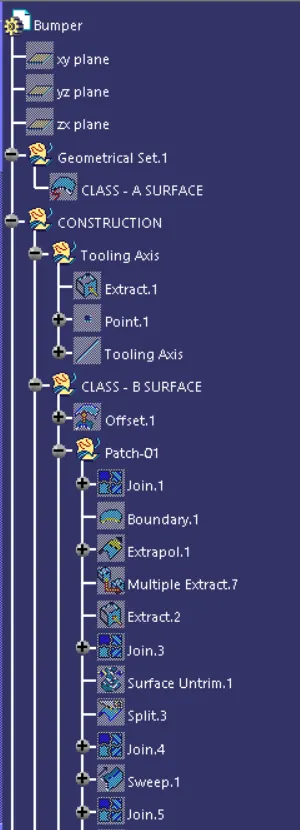
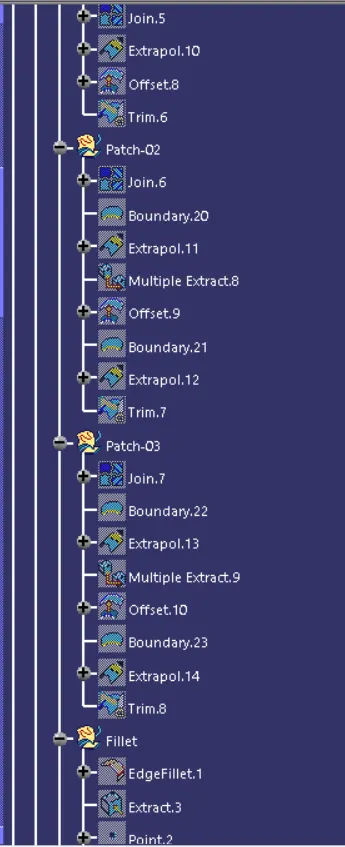
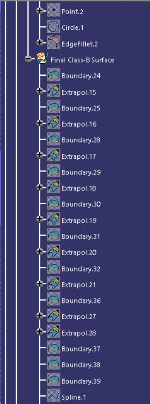
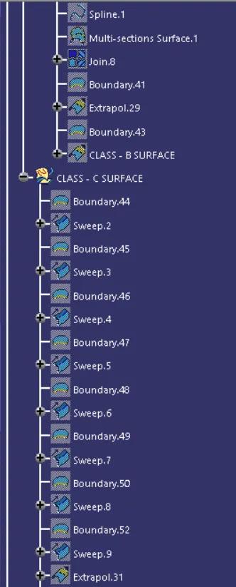
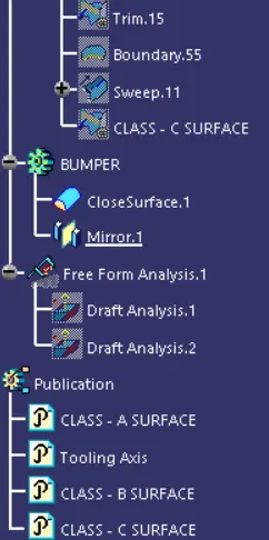
TREE STRUCTURE