Photo Realistic Rendering
THE AMERICAN CHOPPER
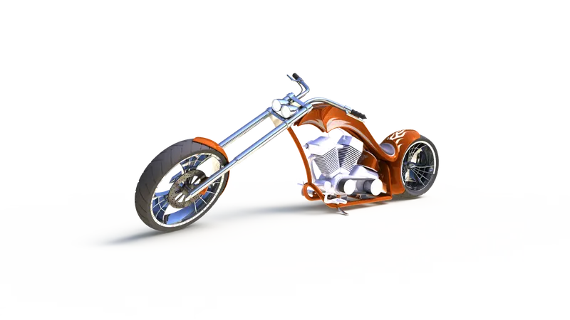
- OBJECTIVE:- Using Solidworks, The objective of this project is to create a model of an American Chopper.
The primary objective was Part Modeling after that Assemble parts under the assembly environment and lastly
Photorealistic Rendering for better visualization.
- INTRODUCTION:- A Chopper is atype of custom motorcycle which emerged in California in the late 1950s. The Chopper is perhaps the most extreme of all custom styles, often using radically modified steering angles and lengthened forks for a stretched-out appearance. They can be built from an original motorcycle which is modified or built from scratch. Some of the characteristic features of chopper are long front ends with extended forks often coupled with an increased rake angle, hardtail frames, very tall Ape Hanger or very short Drag handlebars, lengthened or stretched frames, and larger than stock front wheels.
- DESIGN METHODOLOGY:-
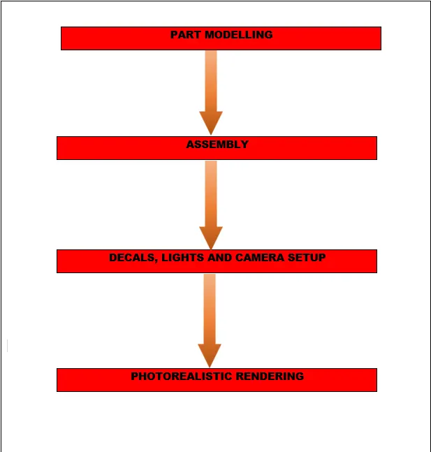
- PART MODELLING
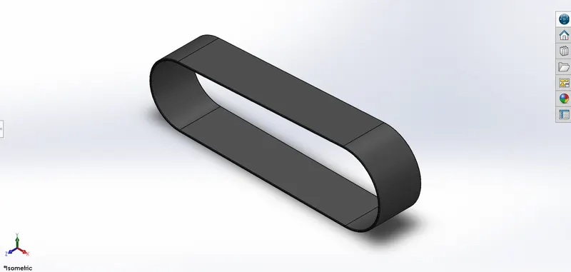
1. TRANSMISSION BELT:-
A belt is a loop of flexible material used to link two or more rotating shafts mechanically, most often parallel. Belts may be used as a source of motion, to transmit power efficiently or to track relative movement. Belts are looped over pulleys and may have a twist between the pulleys, and the shafts need not be parallel.
Commands used: Following were the commands used to model the part,
- 2D sketch
- Fillet
- Smart Dimensions
- Appearance
- Extruded boss/base
- Curve driven pattern
- Mirror feature
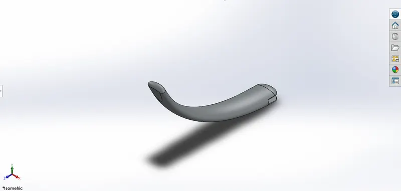
2. KICK STAND:-The kickstand is a swiveling metal bar for holding a bicycle, motorcycle, or another two-wheeled vehicle upright when it is not being ridden and is used for the safety of the vehicle. It is pivoted to the axle in such a way that it can be kicked down below the frame.
Commands used: Following were the commands used to model the part,
- Sketch
- Loft
- Dome
- Extrude Boss
- Extrude Cut
- Fillet
- Split
3. FENDERS:-
A fender is the part of a vehicle that protects and frames its wheels and keeps mud from splashing it. Most modern vehicles have fenders on their front and back wheels.
FRONT FENDER:-It is for the front wheel.
Commands used: Following were the commands used to model the part,
- 2D sketch
- Fillet
- Smart Dimensions
- Appearance
- Split
- Revolve
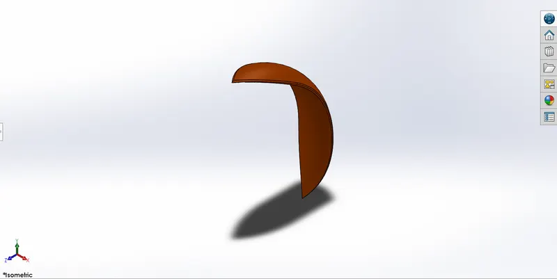
REAR FENDER:-It is for the rear wheel. It also comprises of a decal.
Commands used: Following were the commands used to model the part,
- 2D sketch
- Fillet
- Smart Dimensions
- Appearance and decals
- Split
- Revolve
- Shell
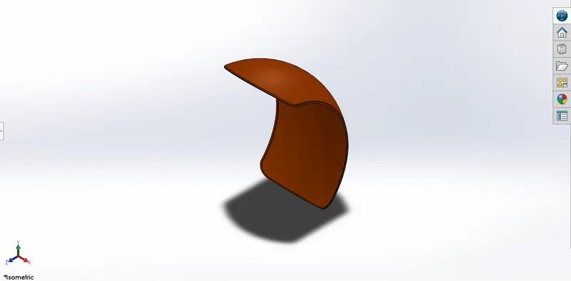
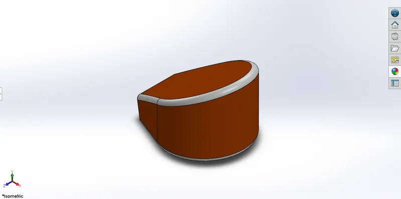
4. OIL TANK:- Oil tanks are used to store engine oil which from there is pumped to the engine and other parts of an automobile for lubrication and maintenance.
Commands used: Following were the commands used to model the part,
- Sketch
- Extrude Boss
- Combine
- Fillet
- Shell
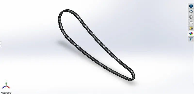
5. CHAIN:- Motorcycle chains are part of the drive train to transmit the motor power to the back wheel. Properly lubricated chains can reach an efficiency of 98% or greater in the transmission. Unlubricated chains will significantly decrease performance and increase chain and sprocket wear.
Commands used: Following were the commands used to model the part,
- 2D sketch
- Fillet
- Smart Dimensions
- Appearance
- Extruded boss/base
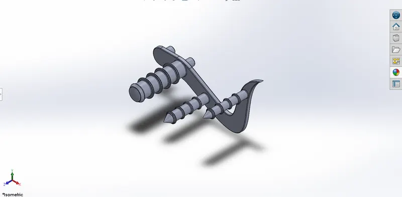
6. PEDAL:- It is the external part attached to the chassis. Used to rest the foot of the rider on to it for the purpose of comfort.
Commands used: Following were the commands used to model the part,
- 2D sketch
- Fillet
- Smart Dimensions
- Appearance
- Chamfer
- Revolved boss/base
- Extruded boss/base
- Linear Pattern
- Dome
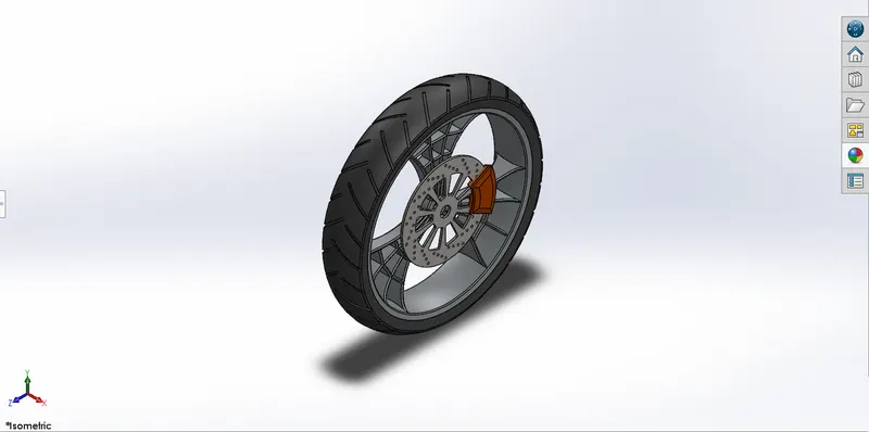
7. FRONT WHEEL:- A wheel is a circular block of a hard and durable material whose center has been bored a circular hole through which is placed an axle bearing about which the wheel rotates when a moment is applied by gravity or torque to the wheel about its axis.
Commands used: Following were the commands used to model the parts,
- 2D sketch
- Offset entities
- Fillet
- Trim entities
- Smart Dimensions
- Appearance
- Chamfer
- Mirror Entities
- Extruded cut
- Revolved cut
- Combine
- Circular pattern
- Extruded boss/base
- Revolved boss/base.
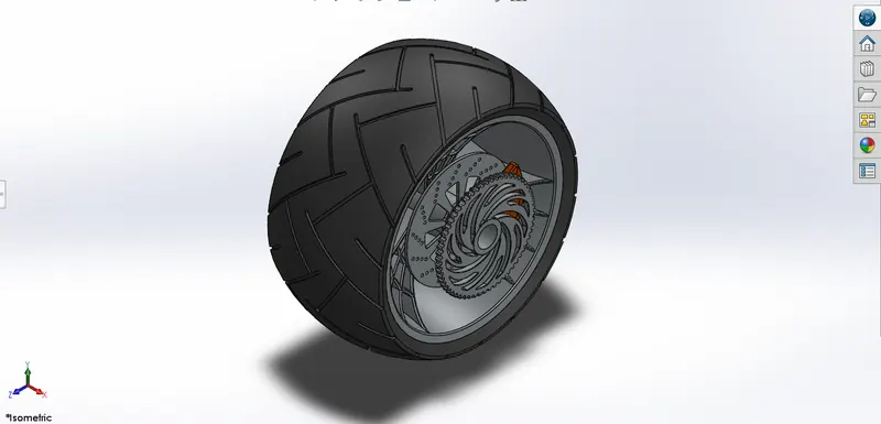
8. REAR WHEEL:- Rear wheel is situated at rear portion of chassis. The rear wheel carries the large sprocket and disc. The power is transmitted to rear wheel from the gearbox through the chain.
Commands used: Following were the commands used to model the part,
- 2D sketch
- Offset entities
- Fillet
- Trim entities
- Smart Dimensions
- Appearance
- Chamfer
- Mirror Entities
- Combine
- Extruded cut
- Revolved cut
- Circular pattern
- Extruded boss/base
- Revolved boss/base.
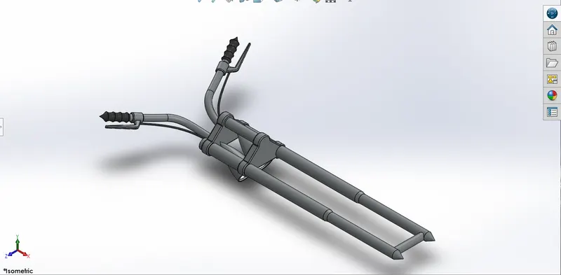
9. FRONT FORK:- The front fork is a suspension component for either bicycle fork or motorcycle fork. The forks can be most easily understood as simply large hydraulic shock absorbers with internal coil springs. They allow the front wheel to react to imperfections in the road while isolating the rest of the motorcycle from that motion.
Commands used: Following were the commands used to model the part,
- 2D sketch
- Fillet
- Trim entities
- Smart Dimensions
- Appearance
- Dome
- Mirror Entities
- Body-Move/Copy
- Combine
- Extruded cut
- Revolved cut
- Circular pattern
- Linear pattern
- Projected curve
- Reference Plane
- Extruded boss/base
- Swept boss/base
- Revolved boss/base.
10. CHASSIS:- A chassis is the load bearing framework of a chopper which structurally supports its function and construction. All the parts of a vehicle wheels, transmission, fuel tank etc. are mounted on it.
Commands used: Following were the commands used to model the part,
- 2D sketch
- Sketch picture
- Fillet
- Split
- Smart Dimensions
- Appearance
- Chamfer
- Mirror
- Combine
- Dome
- Extruded cut
- Projected curve
- Reference Plane
- Extruded boss/base
- Revolved boss/base
- Swept boss/base.
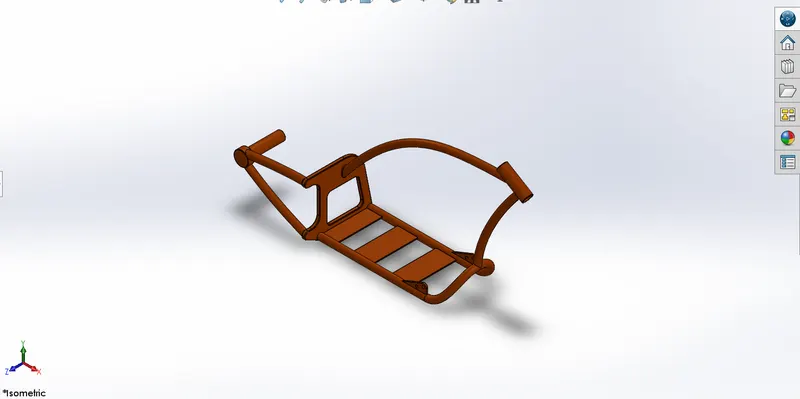
11. ENGINE:- A motorcycle engine is an engine that powers a motorcycle. Motorcycle engines are typically two-stroke or four-stroke internal combustion engines, but other engine types, such as Wankels and electric motors, have been used.
Commands used: Following were the commands used to model the part,
- 2D sketch
- Sketch picture
- Fillet
- Trim
- Smart Dimensions
- Appearance
- Chamfer
- Mirror
- Split
- Combine
- Dome
- Extruded cut
- Circular pattern
- Linear pattern
- Projected curve
- Composite curve
- Reference Plane
- Extruded boss/base
- Revolved boss/base
- Swept boss/base.
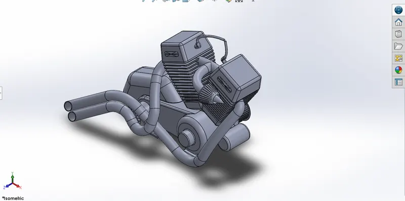
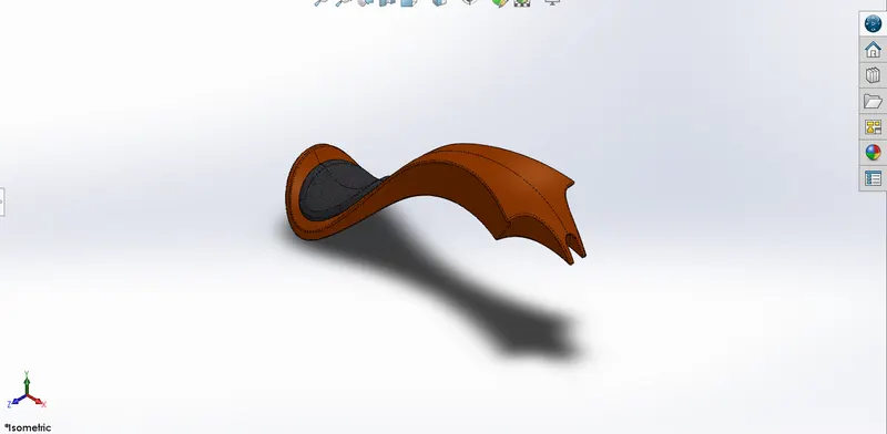
12. GAS TANK:- The gas tank acts as a reservoir to meet the fuel requirements of the chopper.
- Storage of fuel: the system must contain a given quantity of fuel and must avoid leakage and limit evaporative emissions.
- Filling: the fuel tank must be filled in a secure way, without sparks.
- Provide a method for determining the level of fuel in the tank, gauging (the remaining quantity of fuel in the tank must be measured or evaluated).
- Venting (if over-pressure is not allowed, the fuel vapors must be managed through valves).
- Feeding of the engine (through a pump).
- Anticipate potentials for damage and provide safe survival potential.
Commands used: Following were the commands used to model the part,
- 2D sketch
- Sketch picture
- Fillet
- Trim
- Smart Dimensions
- Appearance
- Chamfer
- Mirror
- Split
- Combine
- Dome
- Extruded cut
- Circular pattern
- Linear pattern
- Projected curve
- Composite curve
- Reference Plane
- Extruded boss/base
- Revolved boss/base
- Swept boss/base.
- ASSEMBLY
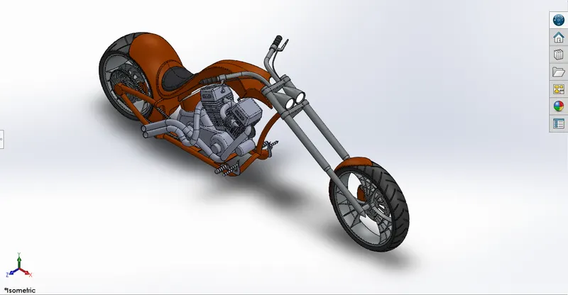
Assembly is done in the assembly environment by inserting all the modeled parts of the chopper using insert part option.
Parts of the chopper are fixed in the assembly environment by giving possible mate conditions or by fixing the planes.
You can build complex assemblies consisting of many components, which can be parts or other assemblies, called subassemblies. For most operations, the behavior of components is the same for both types.
Adding a component to an assembly creates a link between the assembly and the component. When SOLIDWORKS opens the assembly, it finds the component file to show it in the assembly. Changes in the component are automatically reflected in the assembly.
MATES
Mates create geometric relationships between assembly components. As you add mates, you define the allowable directions of linear or rotational motion of the components. You can move a component within its degrees of freedom, visualizing the assembly's behavior.
TYPES OF MATES
The various types of mates available in Solidworks are:-
- Standard Mates - Angles, Coincident, Concentric, Distance, Lock Parallel, Perpendicular, Tangent mates.
- Advanced Mates - Limit, Linear/Linear coupler, Path, Symmetry, Width mates.
- Mechanical Mates - Cam-follower, Gear, Hinge, Rack and Pinion, Screw, and Universal joint mates.
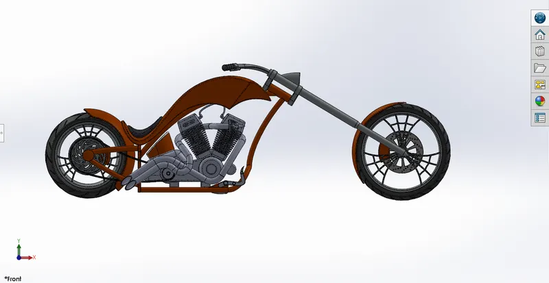
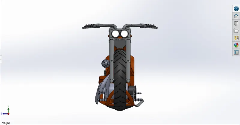
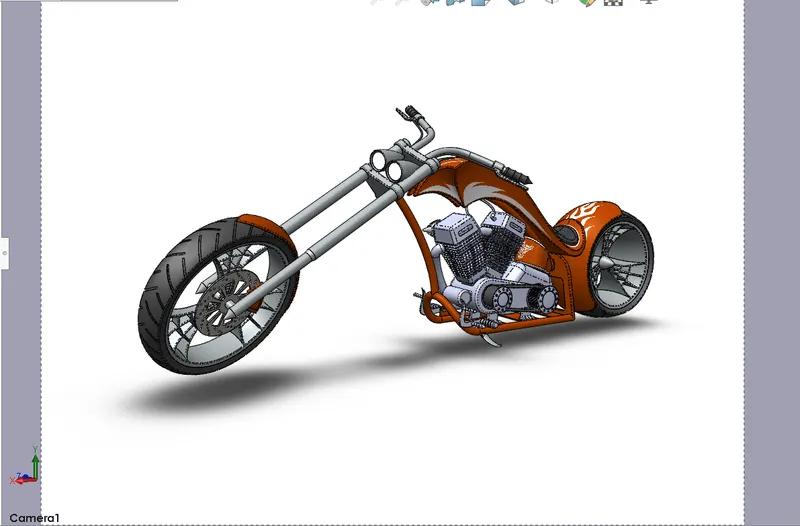
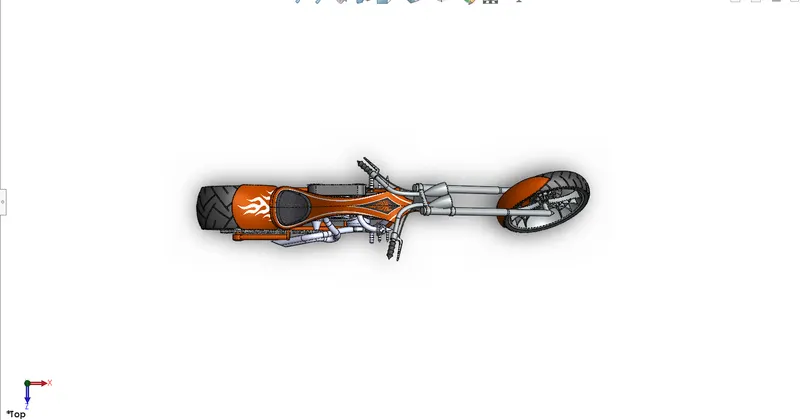
- Images of the assembly: Following are the images of the chopper assembly in different views,
- PHOTOREALISTIC RENDERING OF CHOPPER
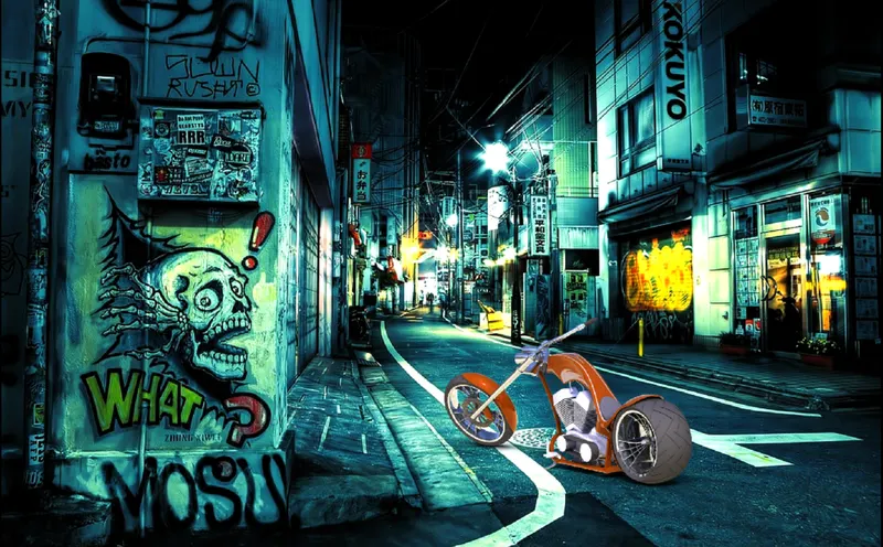
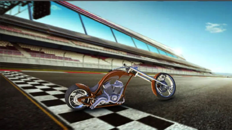
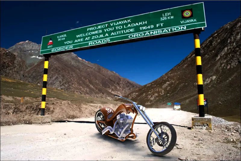
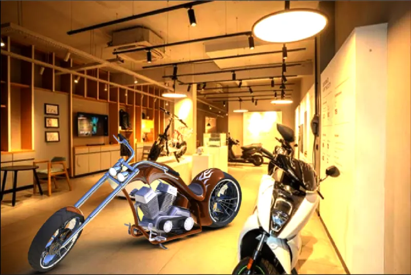
Rendering is the process of creating realistic images of the Photorealistic model with the environment. Rendering has been done in two ways in solidworks. The following are the two ways:-
1. Photoview 360
2. Solidworks Visualize
- PHOTOREALISTIC RENDERED IMAGES OF AMERICAN CHOPPER

CONCLUSION
All the parts of the American chopper were modelled and the assembly was created using Solidworks and the Photorealistic renders of the chopper were created using Photoview 360 only.
NOTE :- 'SOLIDWORKS VISUALIZE SOFTWARE IS NOT INSTALLED IN THE SYSTEM DUE TO SOME ERROR AND THE SAME IS INFORMED DURING ONE ON ONE SESSION. WORK IS DONE ACCORDING TO TECHNICAL TEAM GUIDANCE & PERMISSION'.