Week 9 - Challenge 3 - Bumper
AIM
To create a Bumper Plastic Component through a given Class A Surface and perform Draft Analysis on the final plastic component.
OBJECTIVE
- To make sure that the model meets the requirements of the draft angle.
- To create the Tooling axis using bisecting method.
- To perform Draft analysis on the given Class A Surface.
- To create the required Class B and Class C surfaces.
- To obtain a solid body from the surface using Close Surface feature.
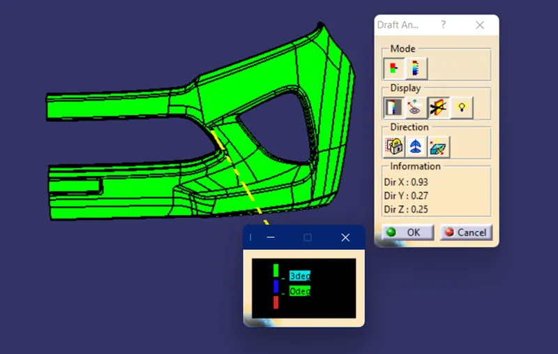
- To perform draft analysis on final plastic component.
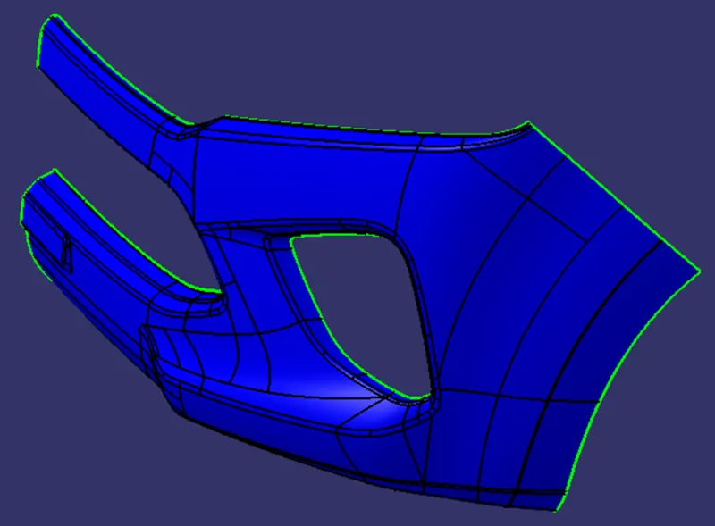
CLASS A SURFACE
- Class ‘A’ surfaces are primarily used in the automotive environment and refer to those surfaces which are visible in a product. In other words: A - class surfaces are those aesthetic/free-form surfaces, which are visible to us (interior/exterior), and have an optimal aesthetic shape and high surface quality.
- The surfaces or regions which are visible nowadays are considered for Class-A modelling. It is one of the reasons why the importance of Class-A modelling is increasing day by day. Majority of the time this term is used in Plastic Part designs.
CLASS B SURFACE
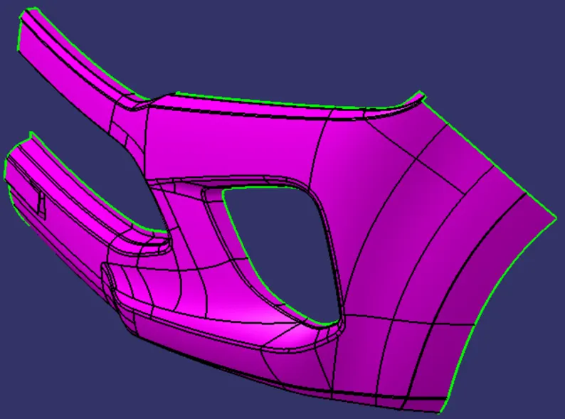
- The Class B surface is created from the Class A surface, keeping the thickness of the component in check.
- The Class B surface resembles an offsetted surface from the Class A.
CLASS C SURFACE
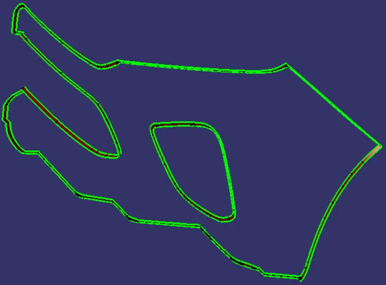
- The Class C surface is used to bind the Class A and Class B surface together in order to form a closed surface.
PROCEDURE
Creating Tool Axis
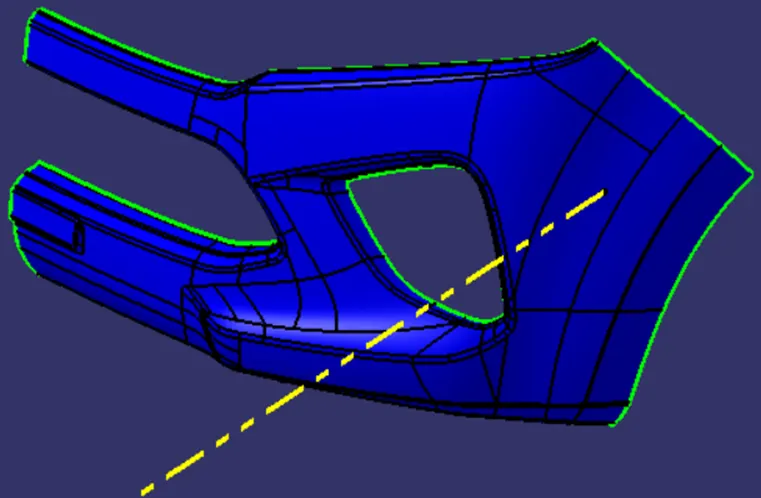
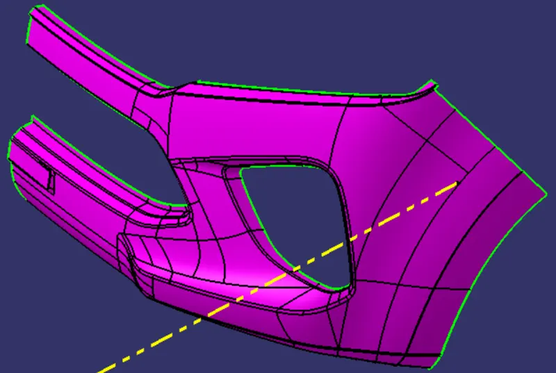
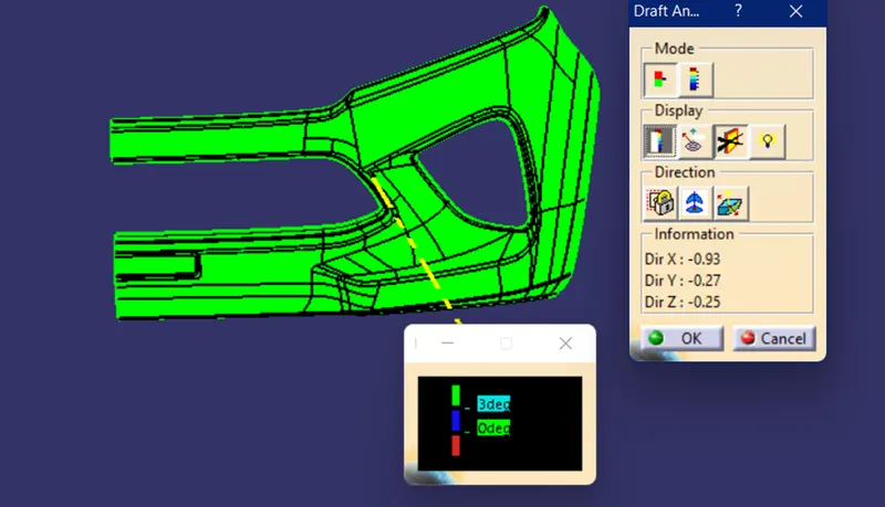
- Initially the given Class-A surface was imported and checked for any discrepancies in the boundary and performed draft analysis on it at 3-degree draft.
- The ejection from the mould after manufacturing the interior trim must have the nominal 3-degree draft angle.
- Hence the tooling directions created by considering the above factor and bisecting method is used.
- The base surface of the class-A was extracted to create a reference point on the surface using the point, create a line in the z-direction and an axis system was inserted to the point.
- Then using projection intersection along the XY-plane is created and the two inclined lines were drawn inside the positioned sketch.
- Then bisecting line with the two inclined lines were created.
- Now the same procedure is done along the XZ-plane.
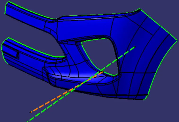
- Bisecting these two lines of different planes, the bisecting line is created and published as a tooling axis.
Creating Class B surface
- First offsetting entire class A surface to 3mm in the inward direction as 3mm is thickness of component.
- Some of errors were created in the offsetted surface like incomplete surfaces, gaps, small patches.
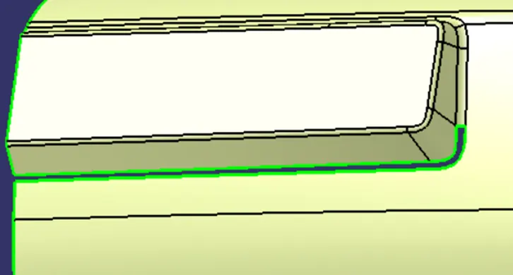
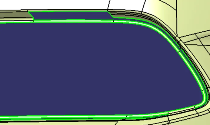
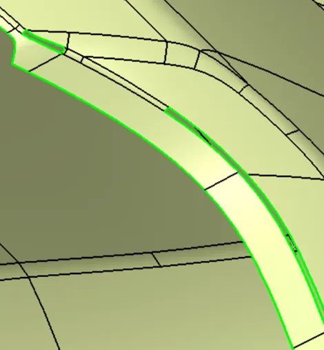
- These errors were solved by extracting surfaces, join by sub-elements to remove, extrapolating, sweep, multi-section surfaces etc commands.
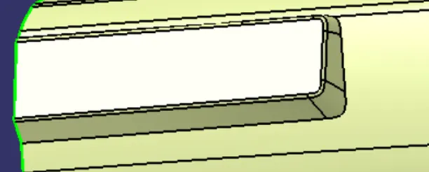
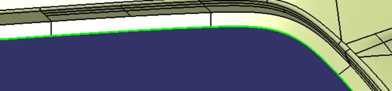
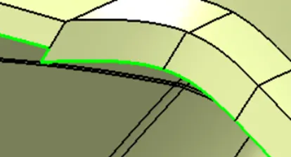
- Finally filleting the edges of the surfaces and obtained the class B surface.
Creating Class C surface
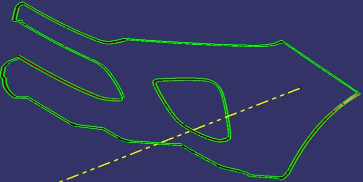
- We first extract the edges from the Class A surface with the help of the multi extract command which we create the path for a sweep for class C.
- We even extract the adjacent surfaces to use them as a reference plane.
- Create a sweep with reference to the curve and the reference surface with a 90-degree angle and give the inside direction Check for the continuity of the surfaces if there is any gap go for extrapolated and trim all together now, we will get the class C surface.
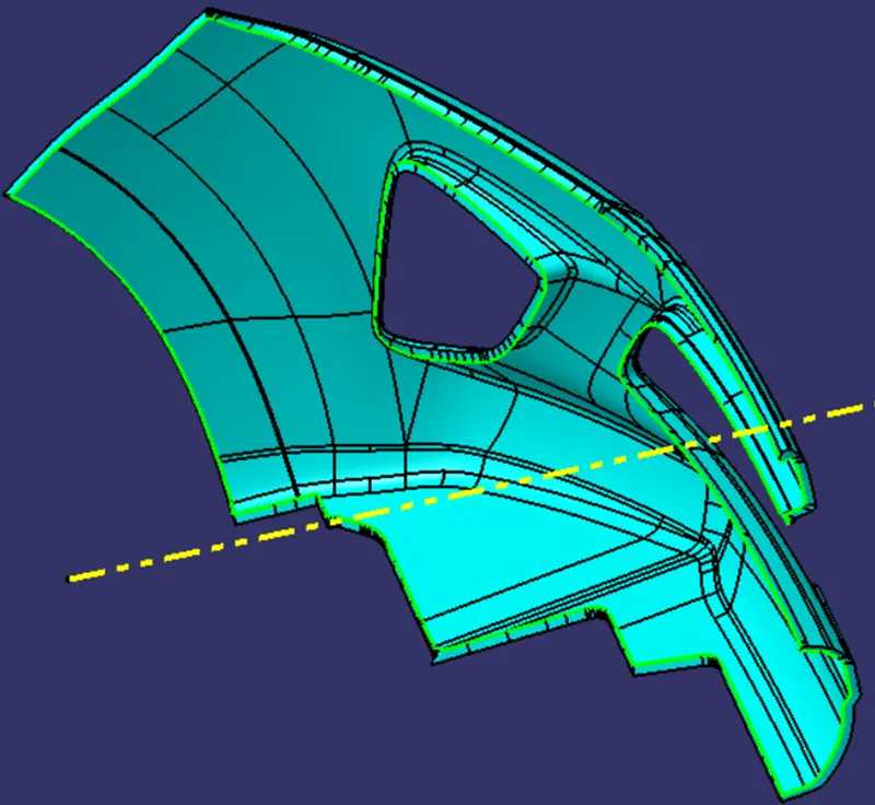
- Joining class-A surface and class-C surfaces together.
Creating Solid Body
- Later, CLASS C and CLASS B surfaces were trimmed and forms the Bumper surface.
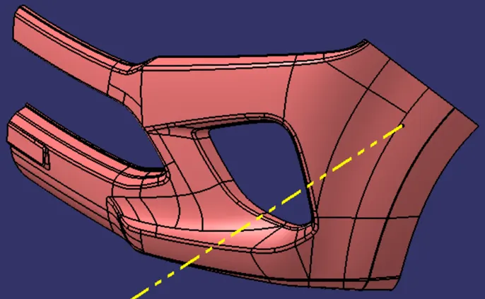
- Using the surface created, the solid component was obtained using the Close surface feature present in the part workbench.
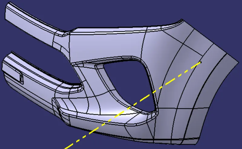
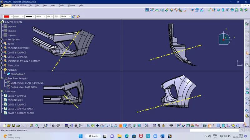
- The Tooling axis, Class A, B and C surfaces were published.
DRAFT ANALYSIS
- First, we should change model into material mode.
- Go to insert and in analysis select feature draft analysis.
- Align the compass along tooling axis and lock it.
- Next click on the surface and see that the surface is within the permissible limit of the values.
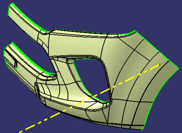
- The green colour area shows that it satisfies the 3-degree draft angle. If not satisfied then by using the Running point tool the area is measured and then altered to get a successful draft for the created tooling direction.
On given Class A surface
On obtained PART BODY
CONCLUSION
- The creation of Tooling axis and Draft analysis were performed.
- The solid component was created from the surface geometry.
- The necessary screenshots and files were attached.
- The Class A, B, & C surfaces and also the Tooling Direction have been Published.