Week 9 - Challenge 3 - Bumper
Class A surface
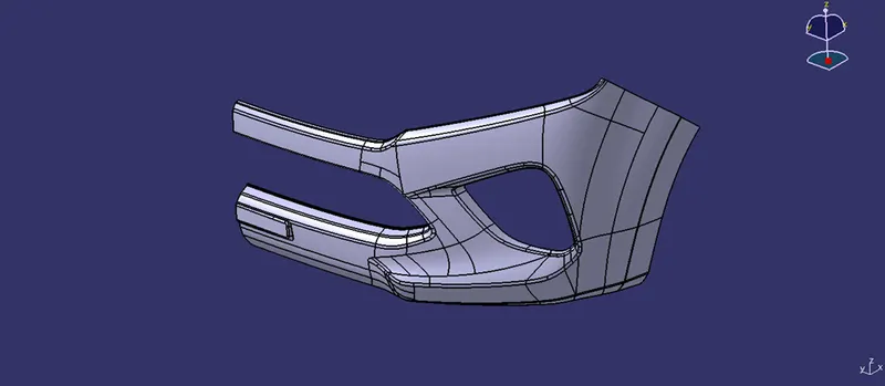
Given class A surface is visually analysed to understand its structure. We have to ensure that given class A surface is free from improper open boundaries and improper faces which is not worked.
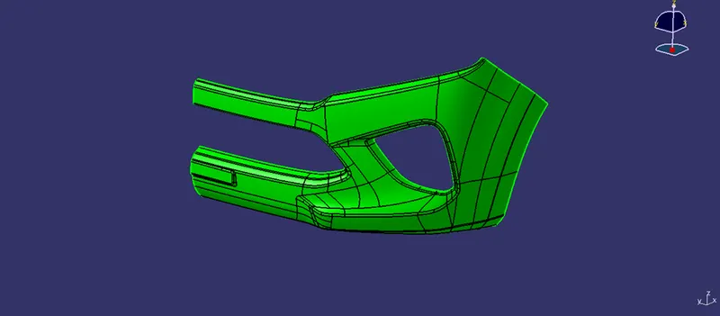
Tooling axis
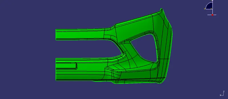
In the below model X direction is selected for creation of tooling axis for the reason it covers all the major surfaces of the components, use of side core and other complex plastic injection moulding features are avoided. With the help of this manufacturing cost and complex operations are reduced, which directly helps to reduce the cost of component.
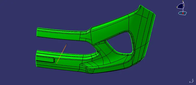
To create a tooling axis, on the class a surface, point is created on mid region. With the help of the point dummy tooling axis is created for our reference with the help of line tool in X direction.
Draft analysis
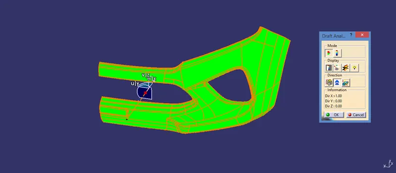
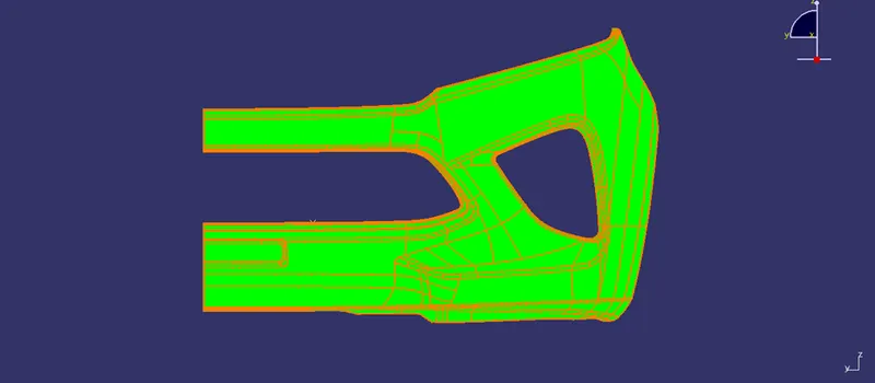
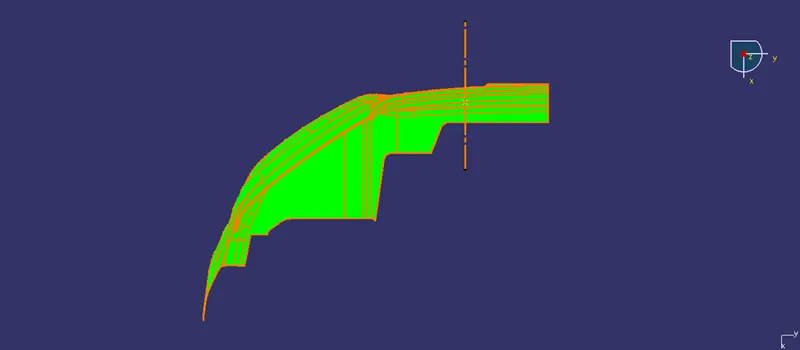
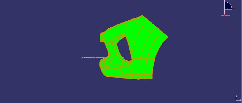
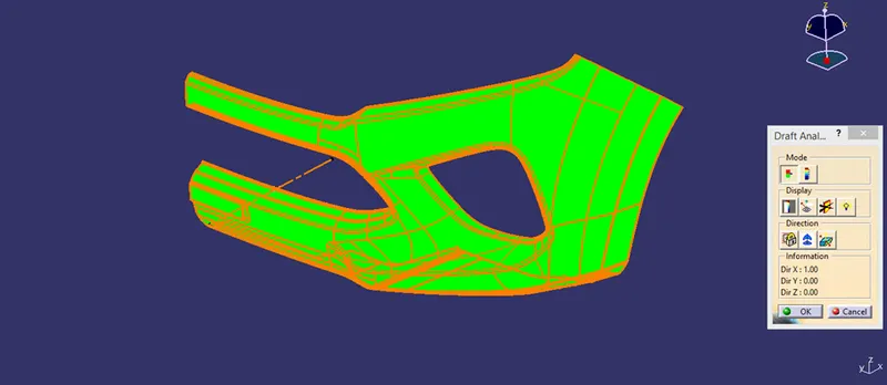
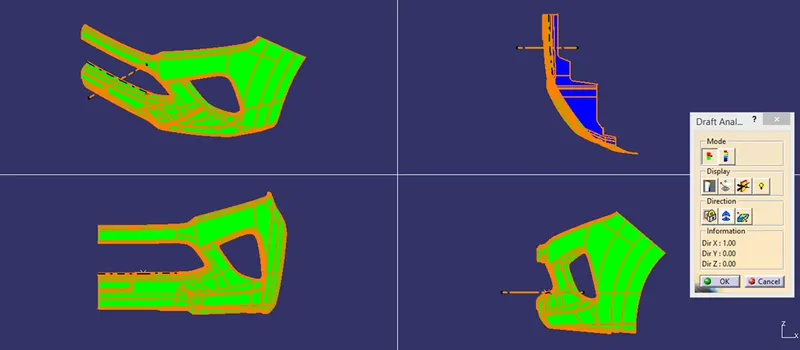
Draft analysis feature helps to check the class A surface, whether it is created as per the moulding standards. An important factor that has to be considered during moulding design is no faces of the component should be in a perpendicular to the base plane. All the faces should be at specific angle as per requirement (say 3 degrees). Using draft analysis feature the surface feasibility can be studied, initially the cordinate system should be placed on the tooling axis, based upon the coordinate system, angular value of the face is viewed with the help of color distribution. The required max and min angle value should be feeded in the scale region. Based upon the preset angle value the colour of the component varies. Using the colour which is displayed on the component is concluded with whether the design standards is followed are not.
Isometric view
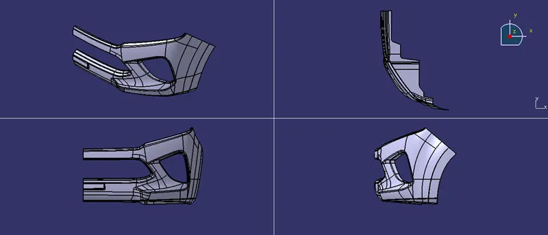
Front view
Top view
Side view
Class B surafce
Class B surface is also called as engineering surface which consist of supporting features to strengthen the component and screw boss to attach the components to the main assembly. Initially main faces of the class A surface should be extracted for creating class B surface. No fillets should be extracted, since offsetting of fillets will create irregular surface or non-proper surface which affects the final output of the component. Once the structure of the component is created then finally sharp edges can be filleted to create final component.
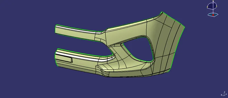
Class C surface
The surface which connects class A and B surfaces are Class C surface, it also closes the surface which helps in creating the solid body of the model which is used in manufacturing purposes.
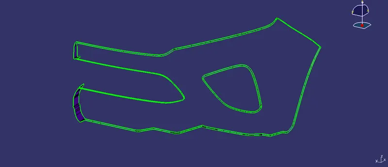
Finished surface model of Bumper
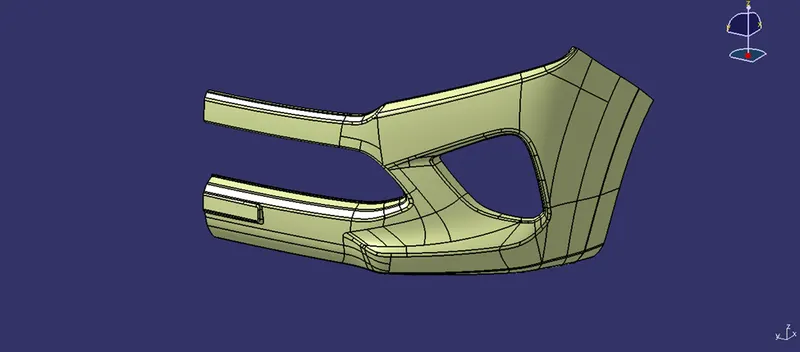
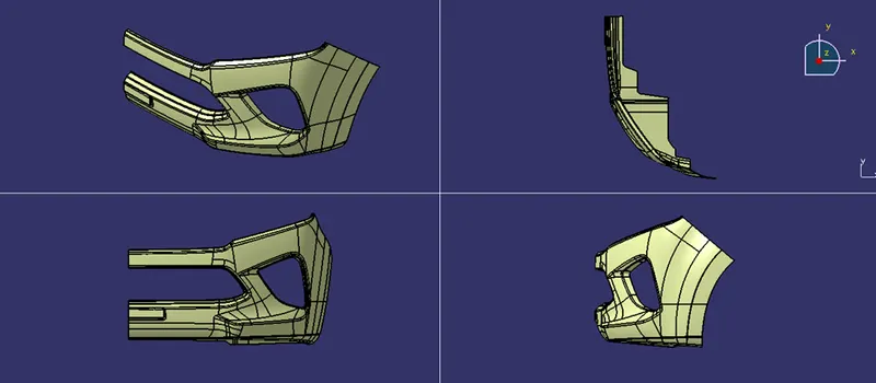
Finished solid model of Bumper
Draft analysis on solid model of Bumper
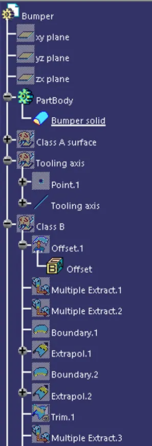
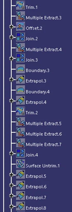
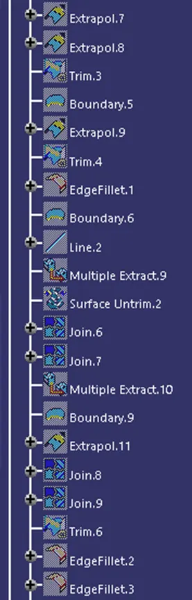
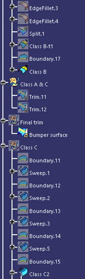
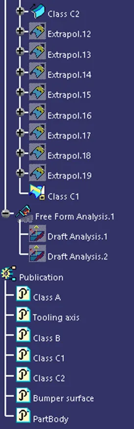
Tree structure