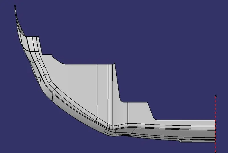
Week 9 - Challenge 3 - Bumper
BUMPER CHALLENGE :-
Object :- Create a tooling axis in proper way by point method for finding better draft analysis from given class A surface. Create draft analysis of class A surface and create class B and class C surface from class A surface. And finally create draft analysis of finished body.
Consider the thickness of the component 3 mm.
Tooling Axis :- Tooling axis or tooling direction is main consideration for plastic part and mold parts because it defines movement of mold part and possibility of plastic part to come-out from mold part (Core and Cavity). In Molding machine arrangement is given to open the mold along a direction which is known as Tooling Direction. The mold is built from two separate halves (Core and Cavity) and tooling direction basically define the direction of mold pulls apart. Tooling direction is known as primary direction.
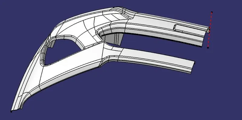
Class A Surface :- In automotive design application Class A Surfaces are created on all visible exterior surfaces (ex; body panels, bumper, grill, lights etc.) and all visible surfaces of see-touch & feel parts in interior (ex: Dashboard, seats, door pads etc.). This can also include beauty covers in the engine compartment, mud flaps, trunk panels and carpeting. This surface has 0 mm thickness.
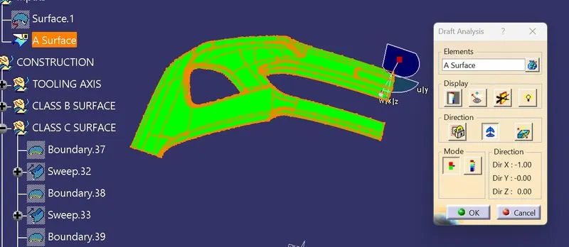
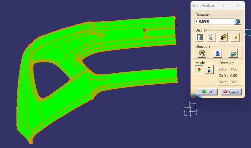
Draft Analysis :- Draft analysis of the surface is carried to check if the surface or part can be manufactured with the required draft angle. Draft angle is needed for the component to clear the core and cavity surface as it would have shrunk towards the center while cooling. The draft angle in this design is 3 degrees. As A surface is a single surface there won't be much difference in color.
Draft analysis for class A surface :-
Draft analysis for final component :-
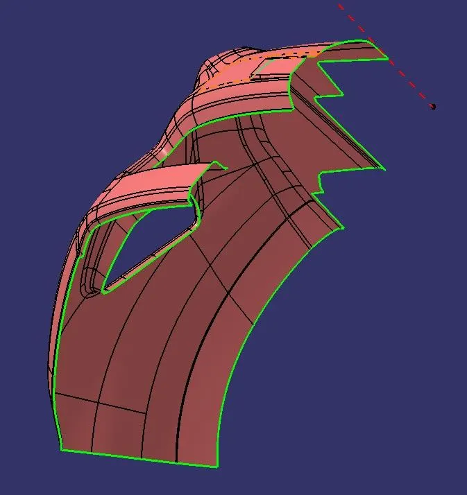
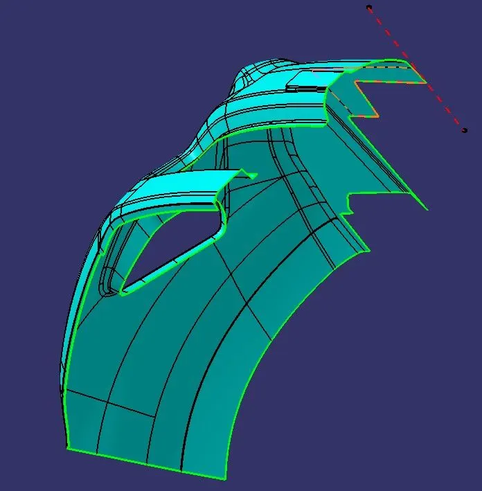
Class B Surface :- The surface which is back side of class A surface is called class B surface. Mostly it is not visible, it is created with the help of class A surface with some distance (thickness) like 2 mm, 3 mm etc. Here I created class B Surface on 3 mm from class A Surface.
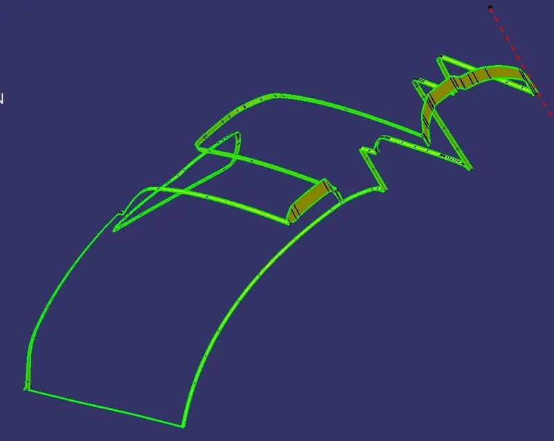
Class C Surface :- The A and B surfaces are connected by another single surface which is called the C surface. It is created by using sweep with A surface acting as the reference surface and curve created from the boundary of the same surface.
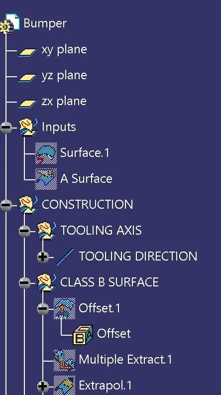
TREE STRUCTURE :-
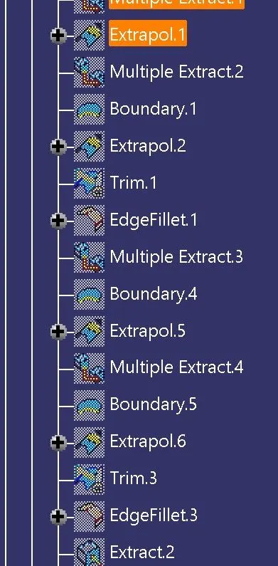
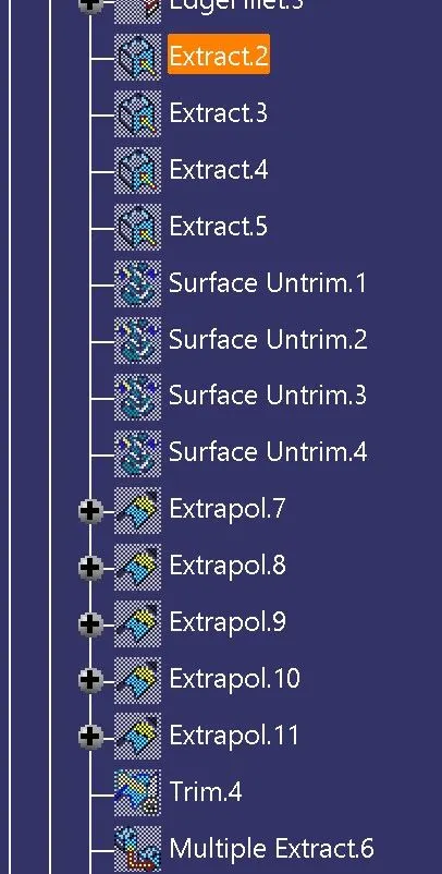
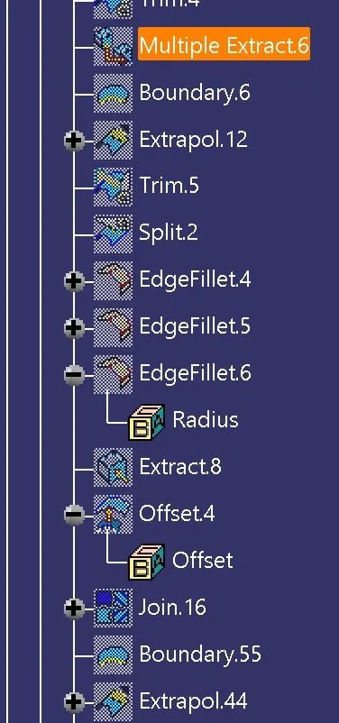
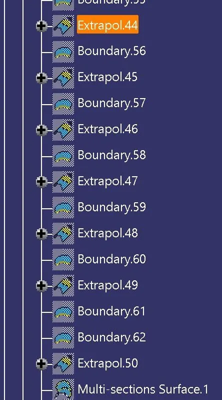
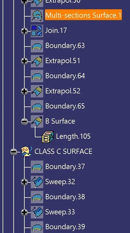
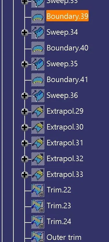
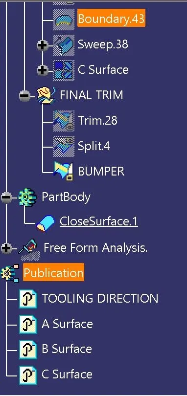
Views from the different orientations of the Bumper Part Body:
Isometric View :-
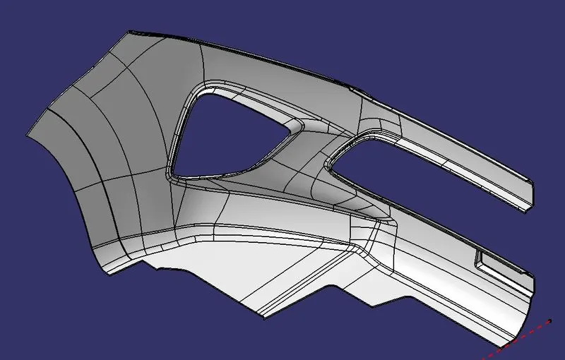
Front View :-
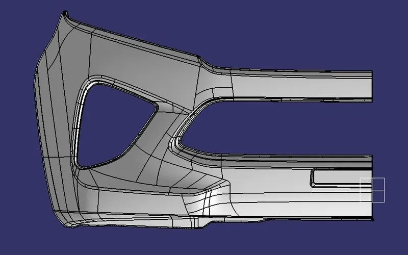
Side View :-
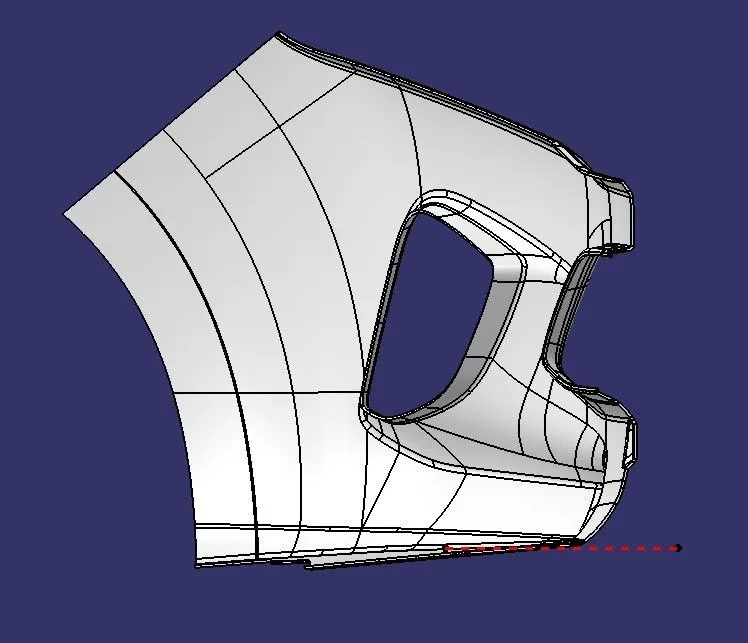
Top View :-
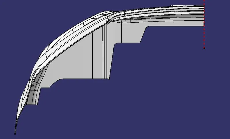
Bottom View :-