Week 9 Challenge
1. Design of dual slope (pitched) roof frame
Design a 3 hinged pitched roof frame of a steel building. Assume no wind load acting on the walls and roof. Analyse the frame structure and draw bending moment, shear force and axial force diagrams of the frame. The slope of the roof is 1 in 10 and the roof is accessible for maintenance purpose (assume 75 kg/m2) only. Dead load on the roof are given below. Assume bay spacing as 5 m and frame width is 20 m. (Design code as per AISC:ASD. No seismic load consideration required)
Weight of roofing sheet = 5kg/m2
Weight of purlins + tertiary members = 25 kg/m2
Roof Slope 1:10
tan θ">θ�= (1/10)
θ">θ� = 5.71 degrees
Bay Spacing = 5 m
Live Load = 75 kg/m2 = 0.735 kN/m2 = 0.735 x 5 = 3.675 kN/m
Dead Load = 5 kg/m2 + 25 kg/m2 = 30 kg/m2 = 0.294 kN/m2 = 0.294 x 5 = 1.47 kN/m
Procedure:-
Open the STAAD Pro Software and create a new model as shown below.
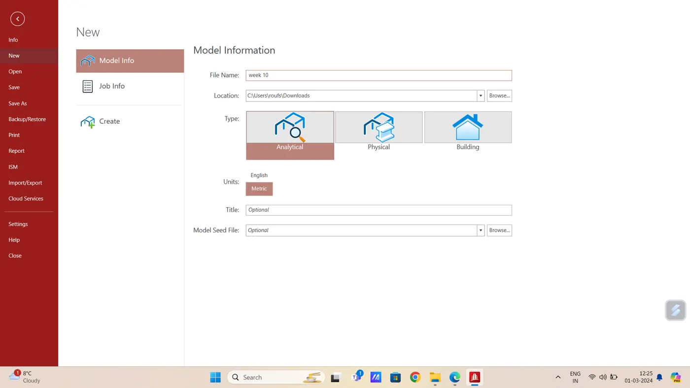
- Using Add beam command join two Nodes
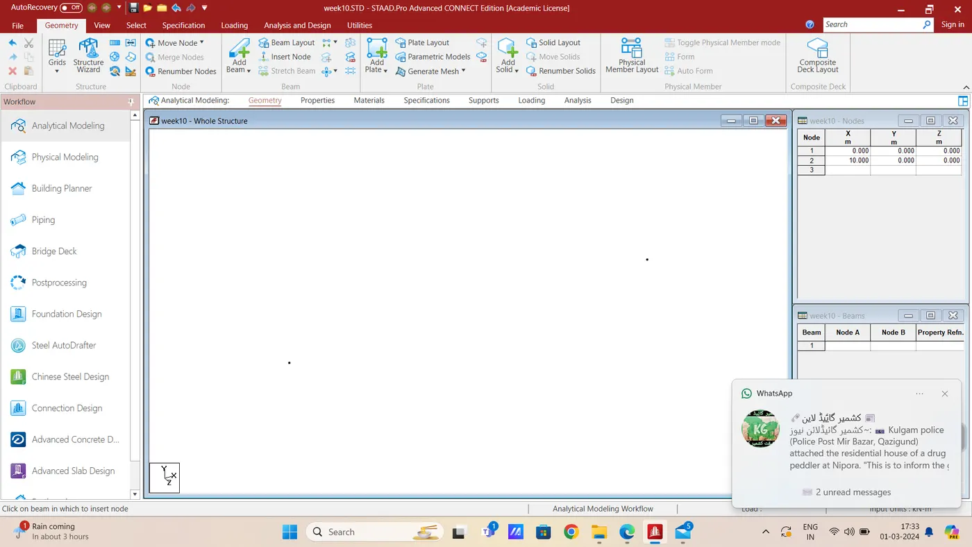
- Create one more node at (0,5,0) assuming the height of the column as 5m
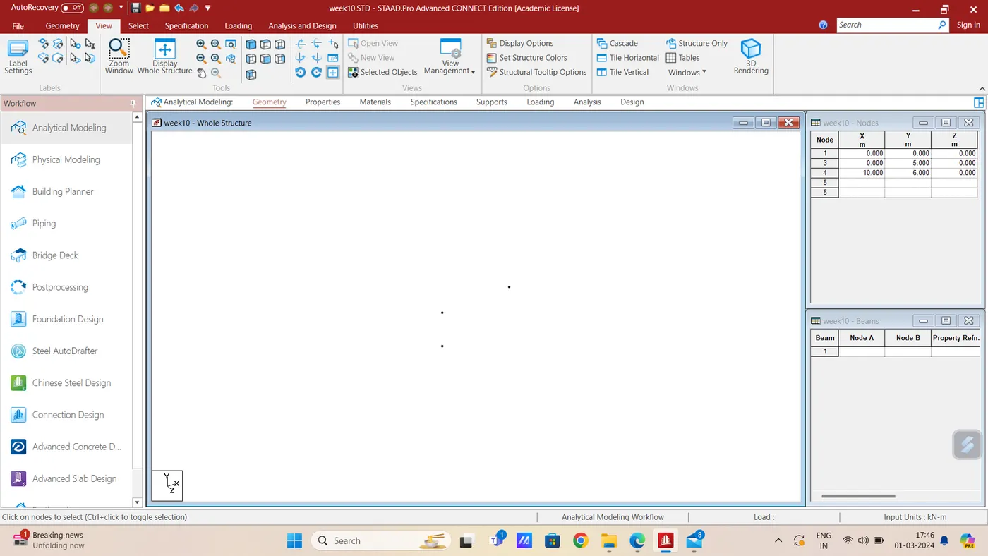
- Move Node No # 4 vertically by 1 m for maintaining slope of 1:10
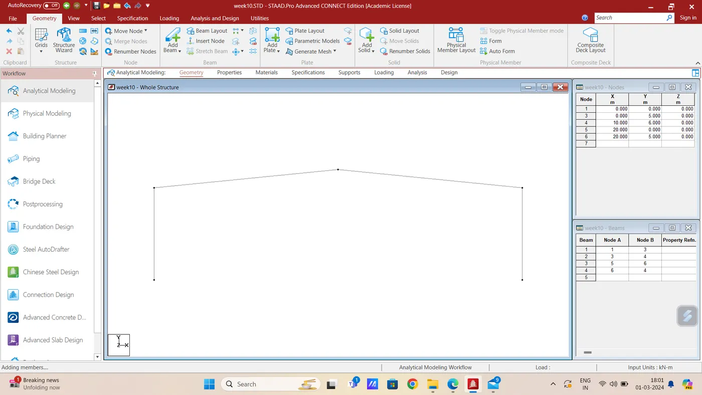
- Now add 2 more points and add beams to complete the frame
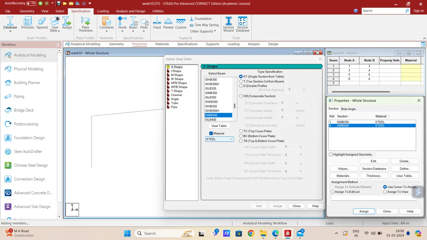
- Define Section properties in the Properties Tab.
- Then assign Sections to the members.
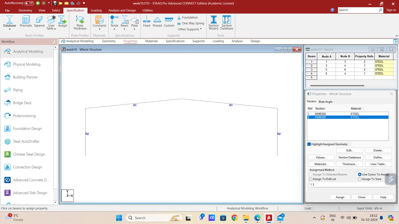
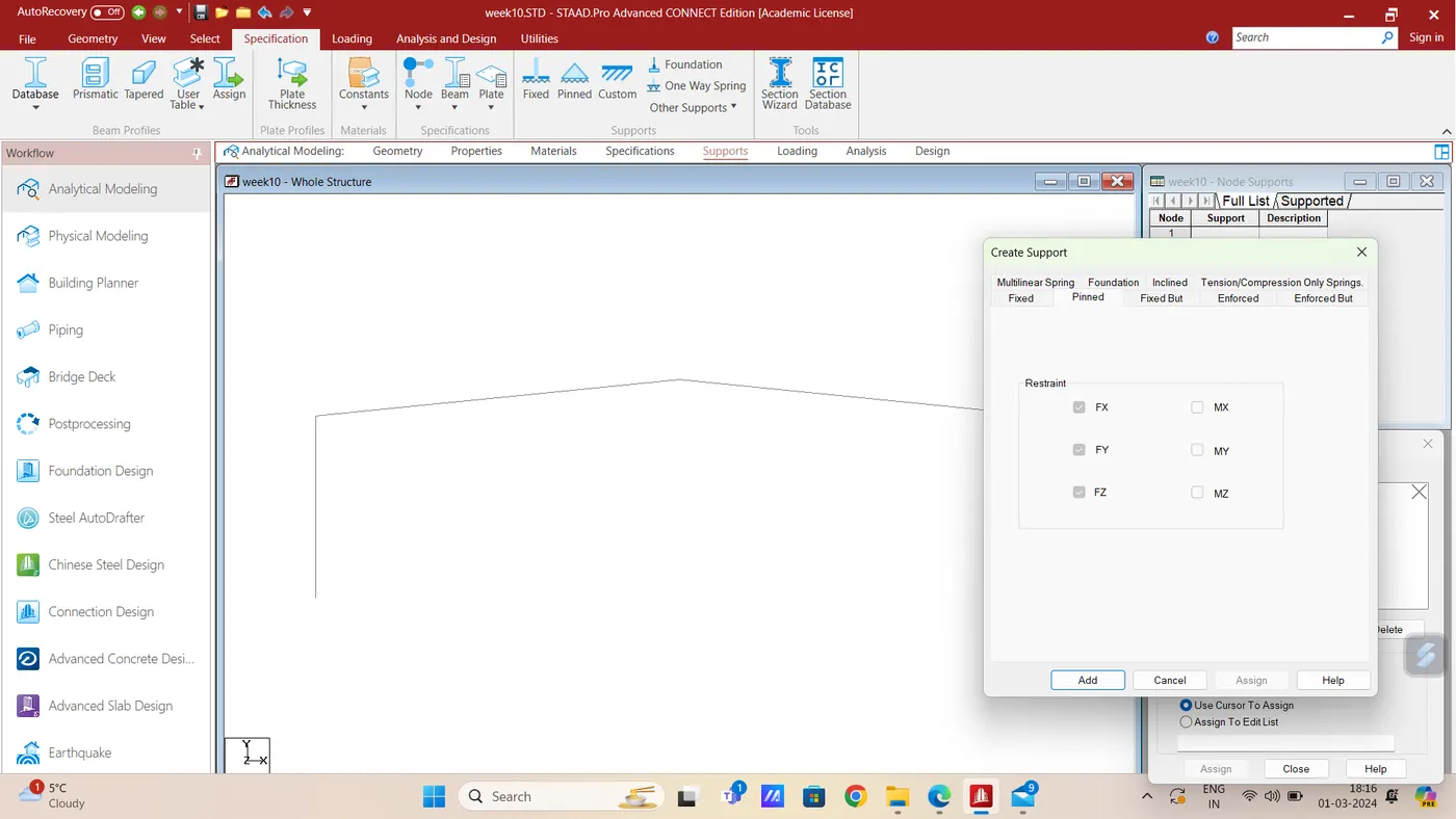
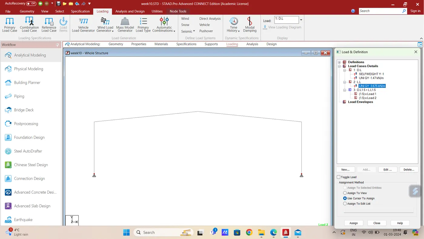
- Now create and assign the Pinned support
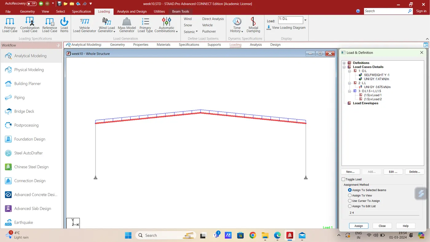
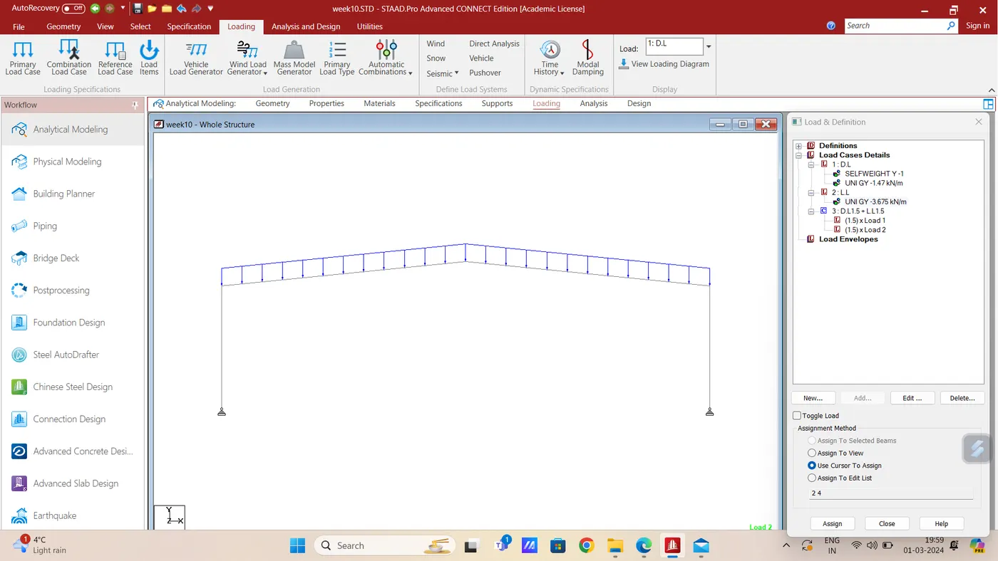
- Add Dead Load, Live Load and Load Combination to the members.
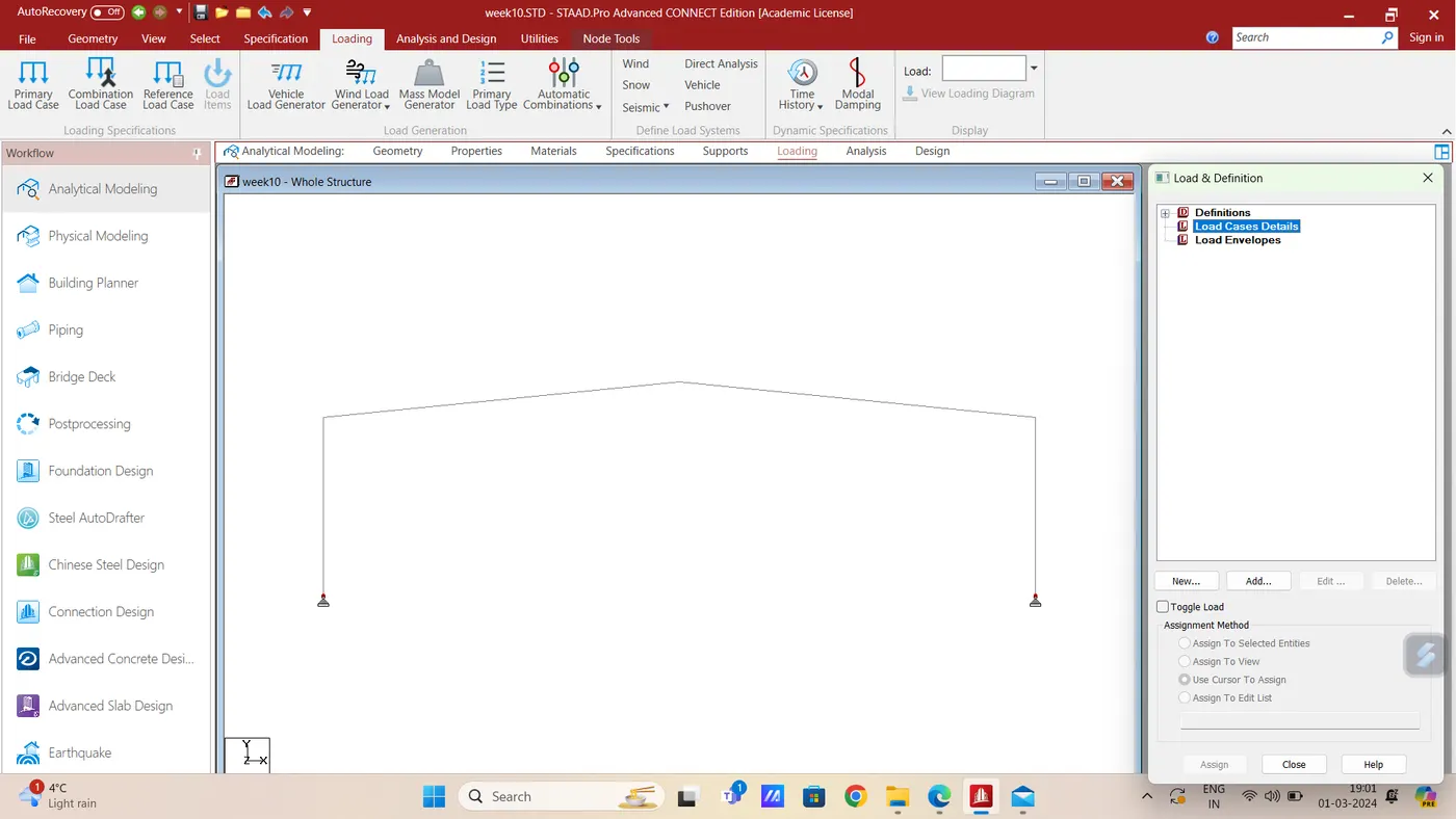
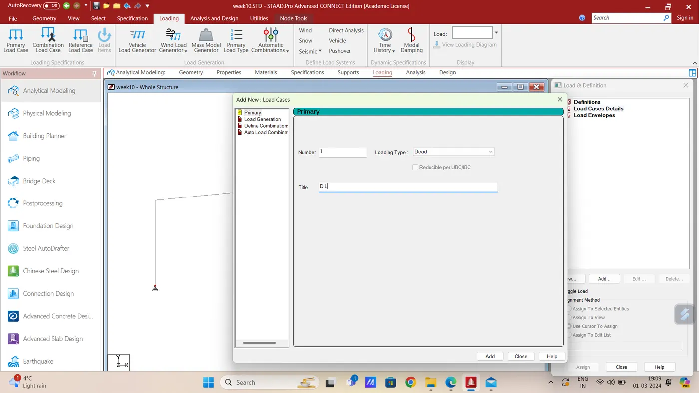
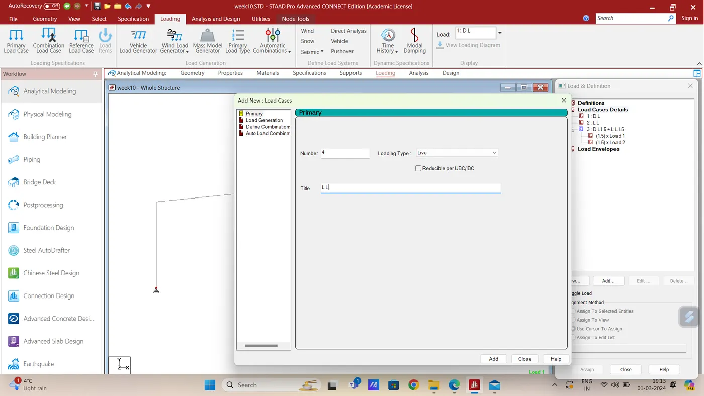
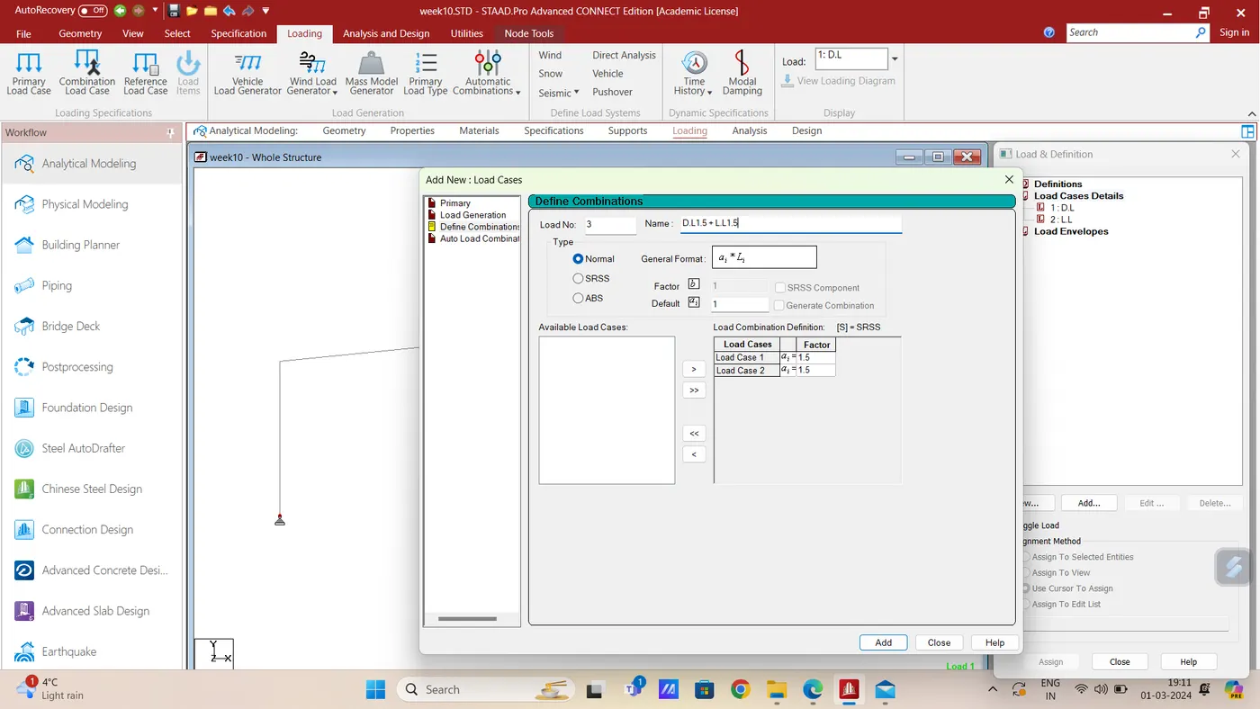
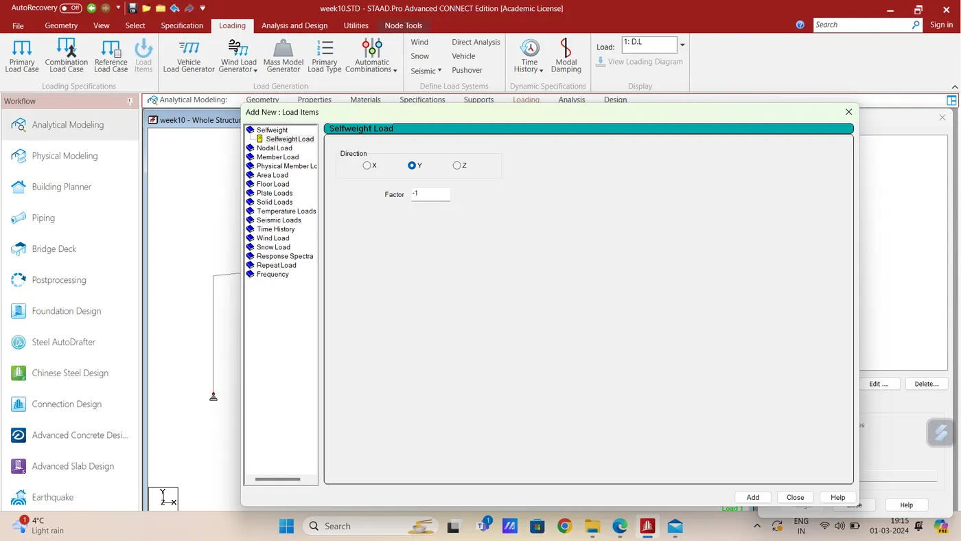
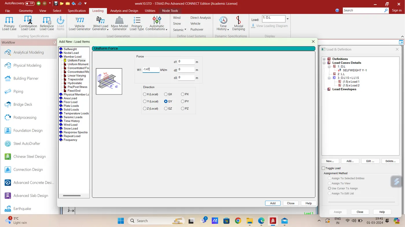
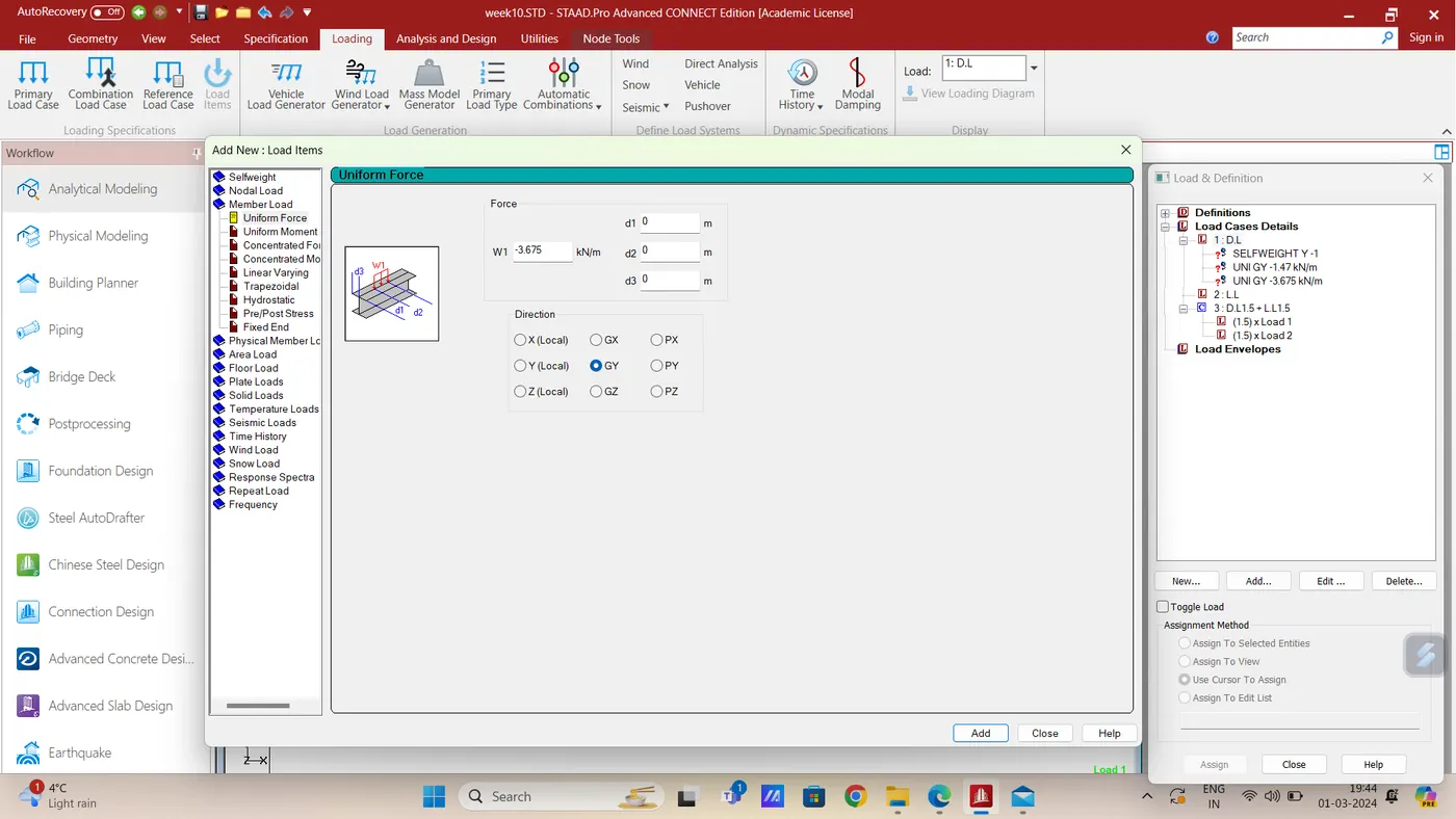
Now assign the DL and LL as shown
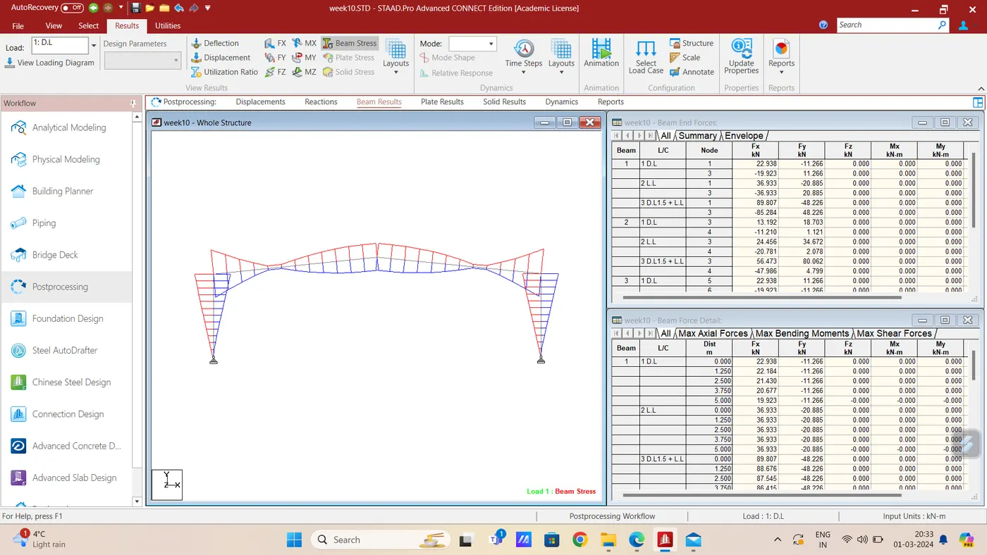
2. Draw Bending Moment diagram for following Frame using STAAD.Pro
Figure 1)
Aim & Introduction- To draw Bending Moment Diagram of the given model with following given data-
Span = 20 m
Height of the column = 10 m
Slope = 5.71 Degree
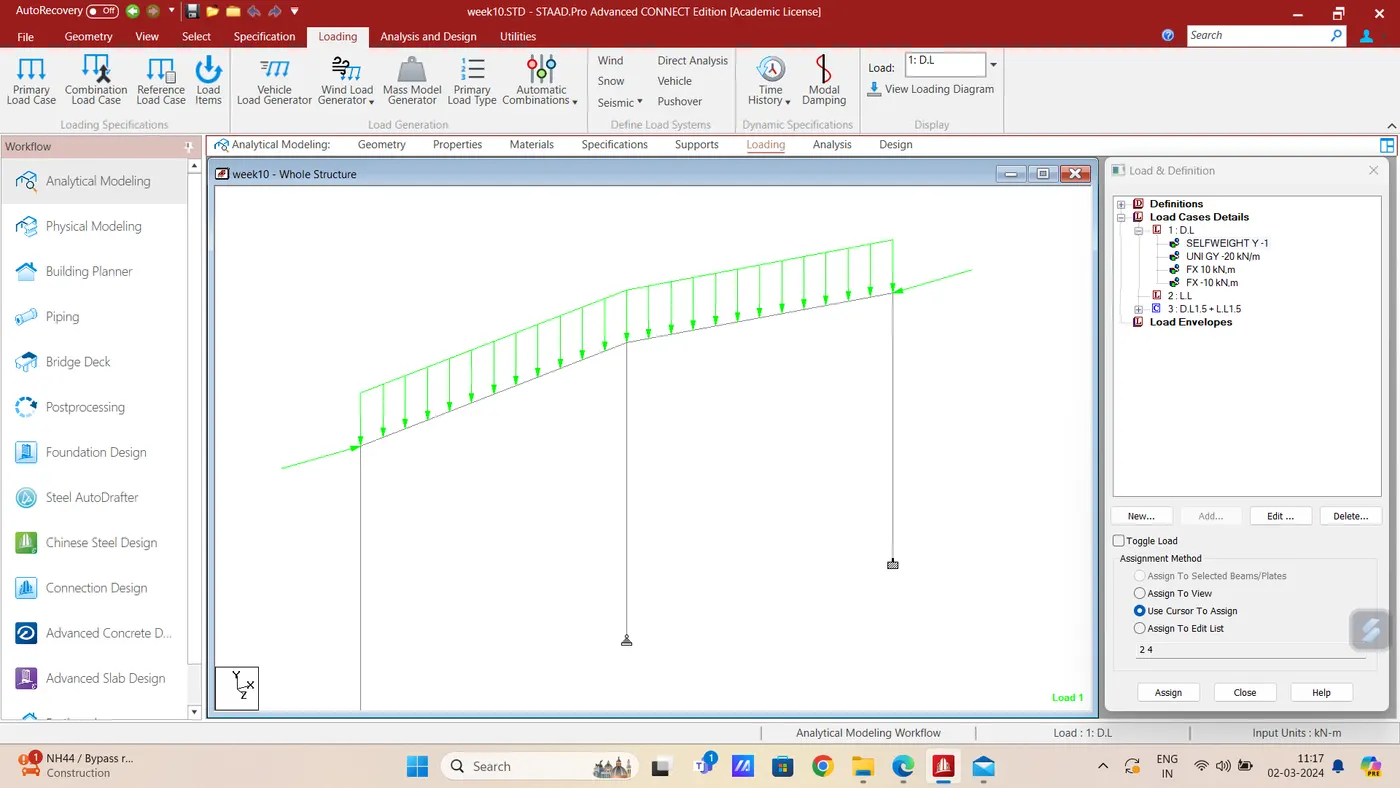
Support Conditions = Fixed support at two exterior columns & Pinned support at middle column
Loading = 20 KN/m UDL on Rafter & 10 KN Nodal load along X direction at node A & C
Procedure- First of all model is prepared with given data as shown below-
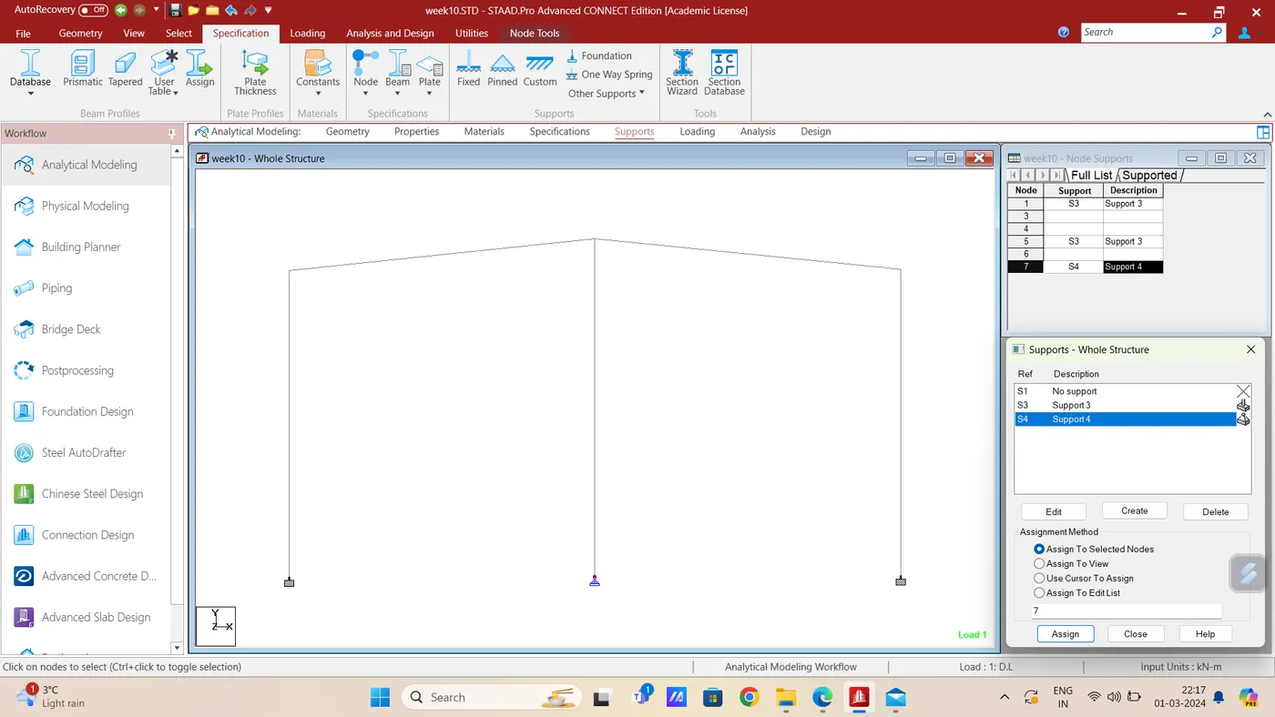
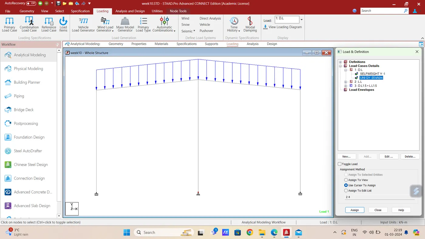
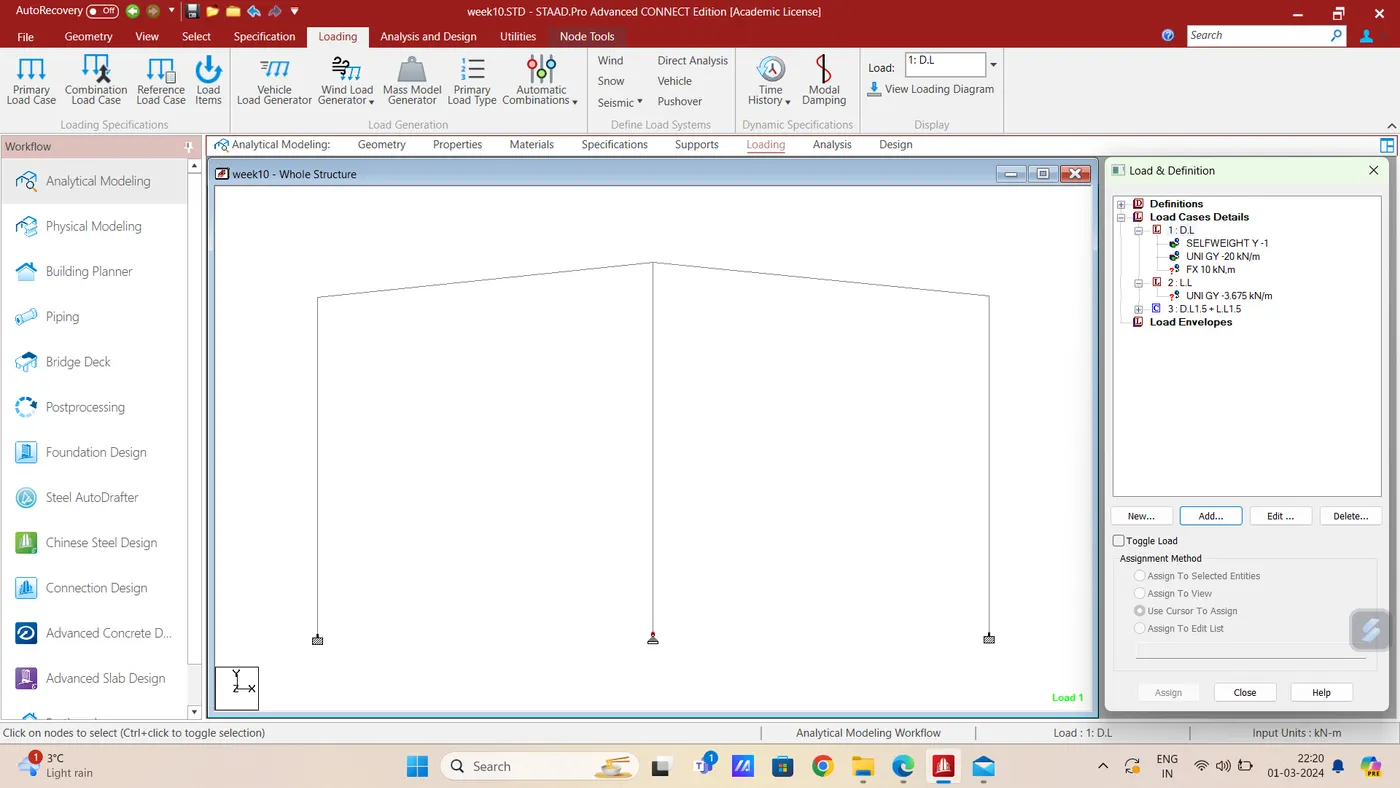
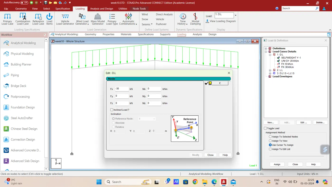
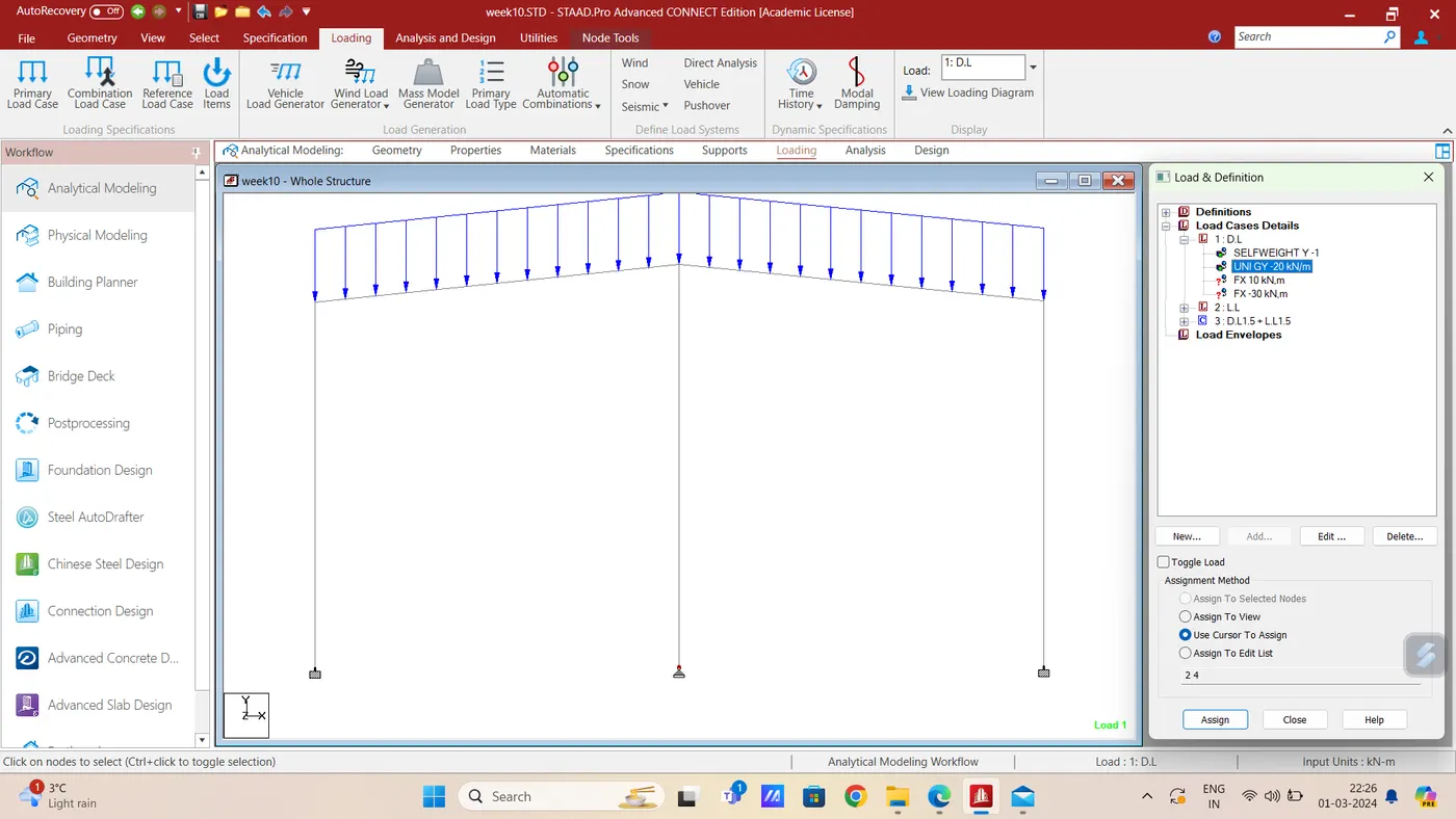
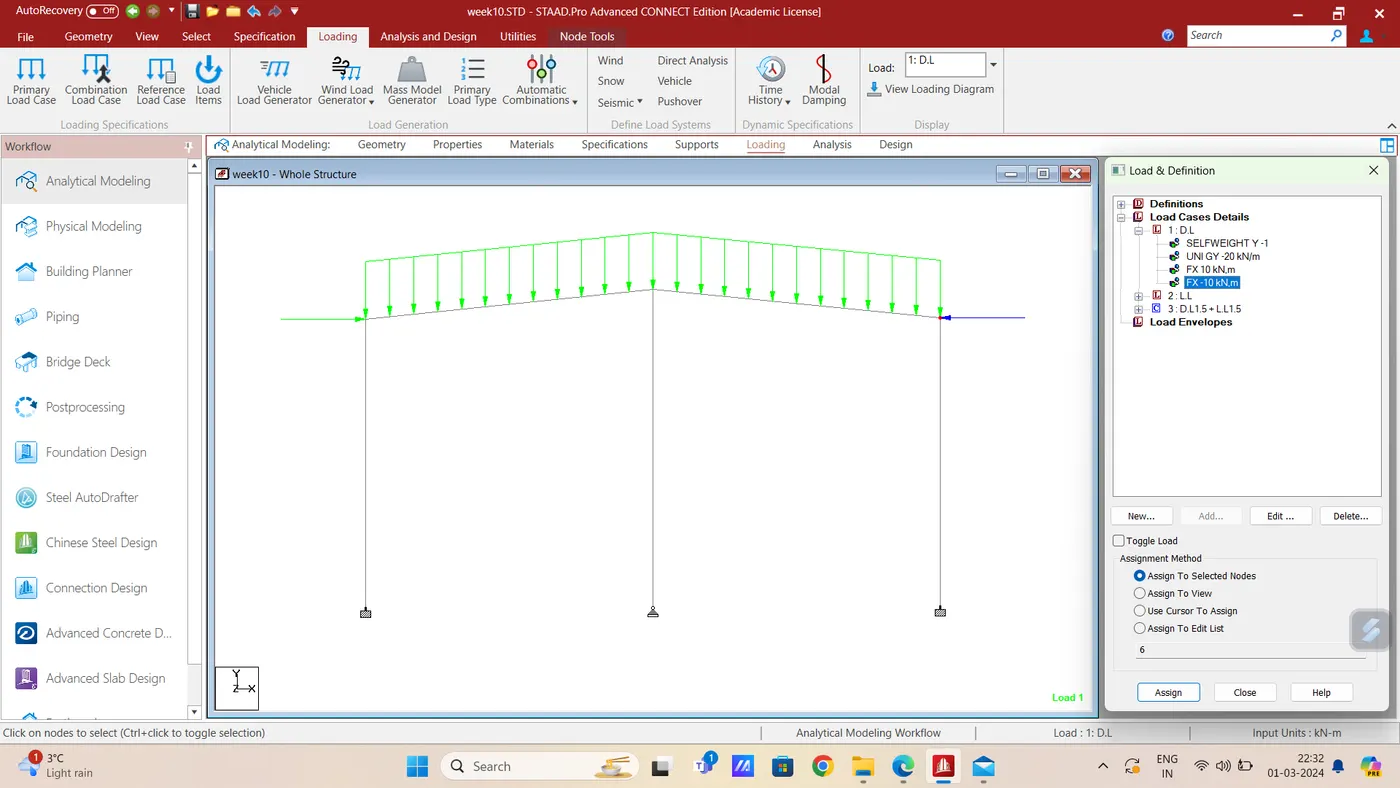
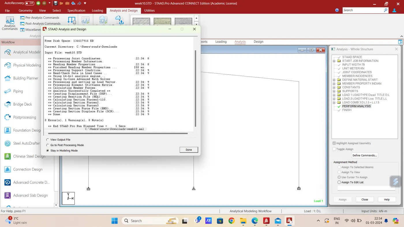
Now lets run the analysis
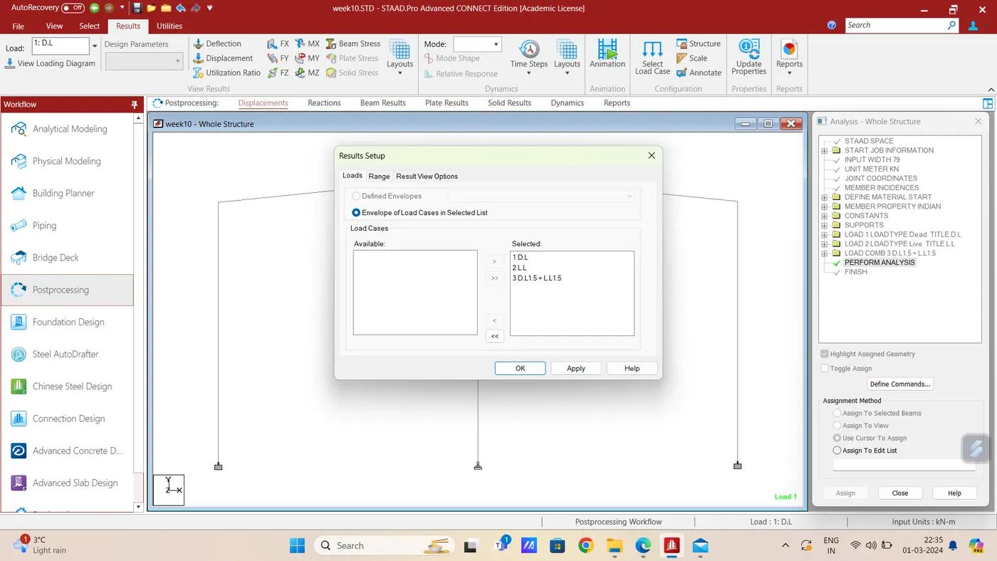
Go to Post processing
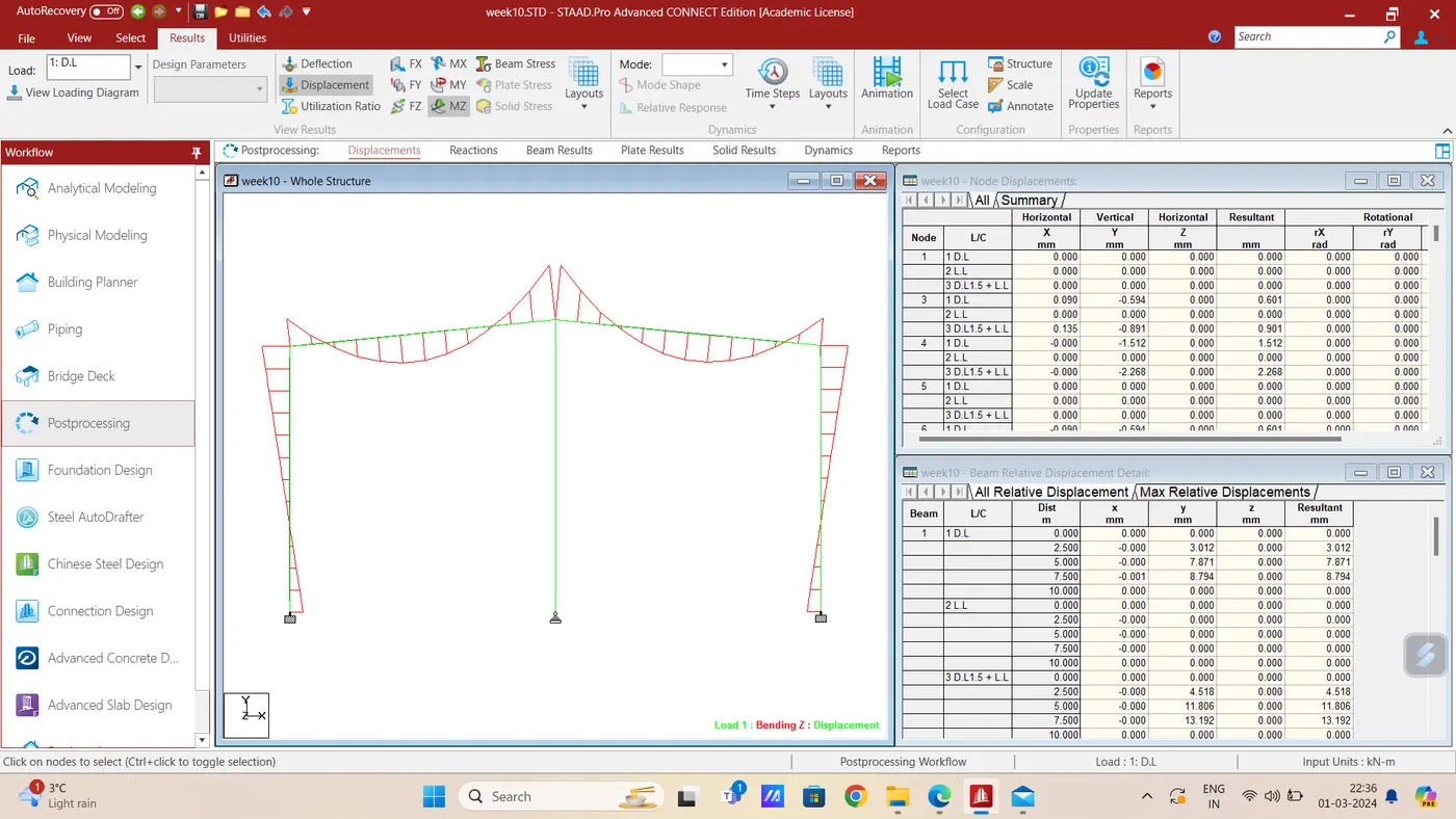
Mz - BMD:
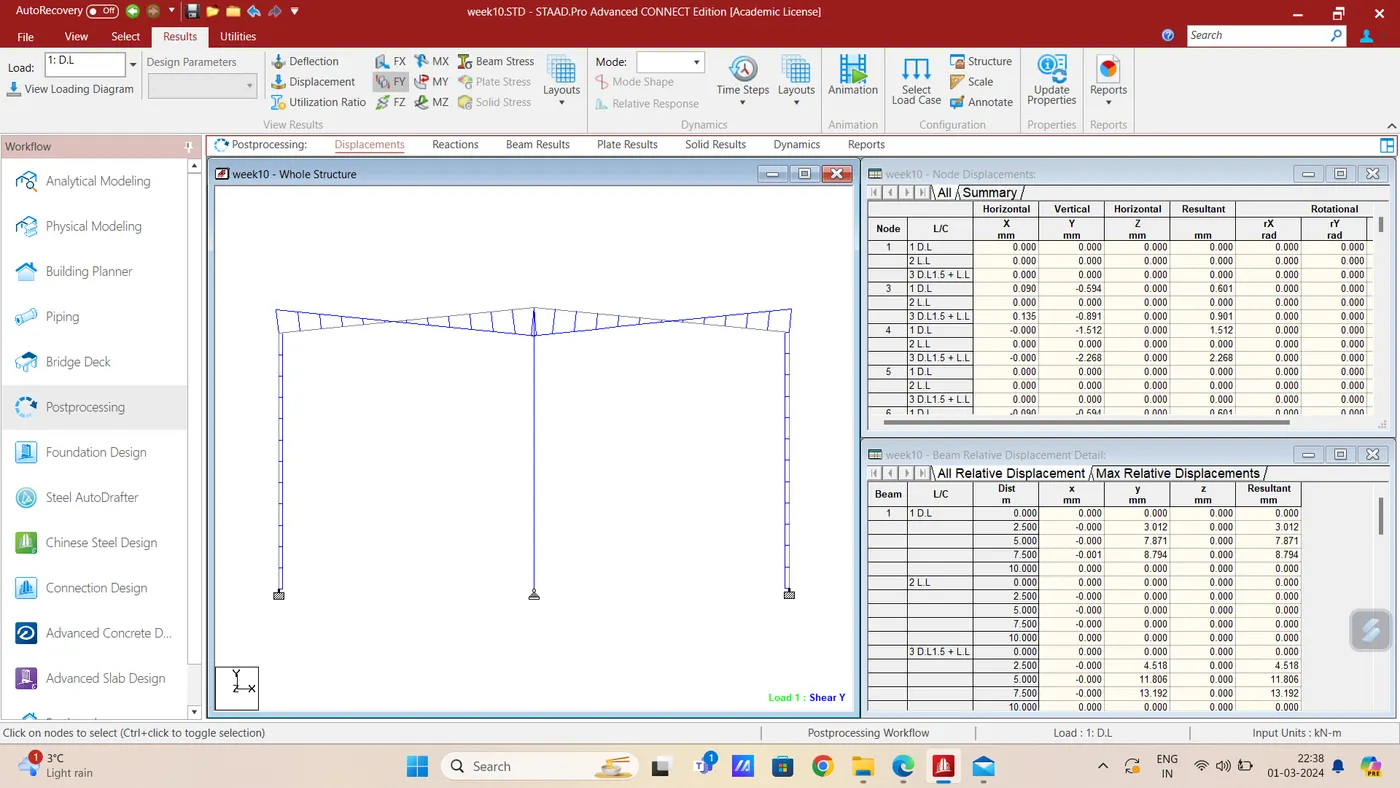
Fy - SFD:
Fx - AFD:
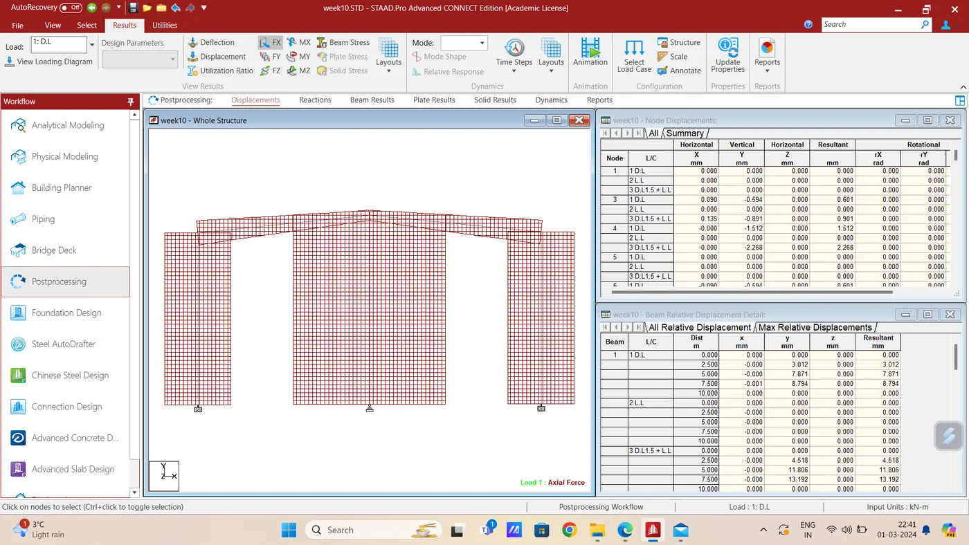
Figure 2)
Aim & Introduction- Bending Moment Diagram of given frame is required to be drawn using Staad.Pro software ,
Given data for frame: Frame with span= 8 m
Column height on one side =10 m
Support Conditions: Both columns are Hinged supported and also hinged at the center center of beam there is hinge
Loading : Nodal load of 10 KN/m at hinged support of roof beam & UDL of 10 KN/m on the column on left side alonf X axixs.
Procedure : Frame with given data is created using, Loading is assigned as per given detaials and member properties are also assigned . 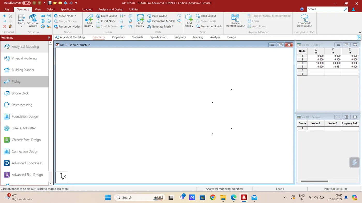
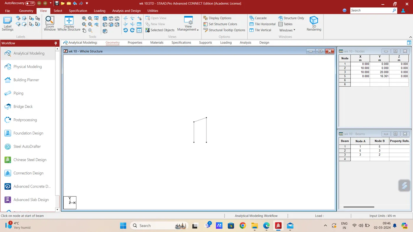
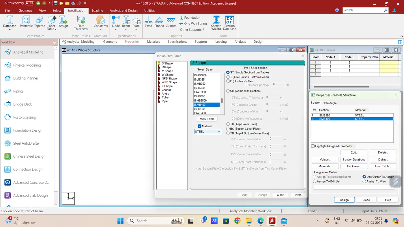
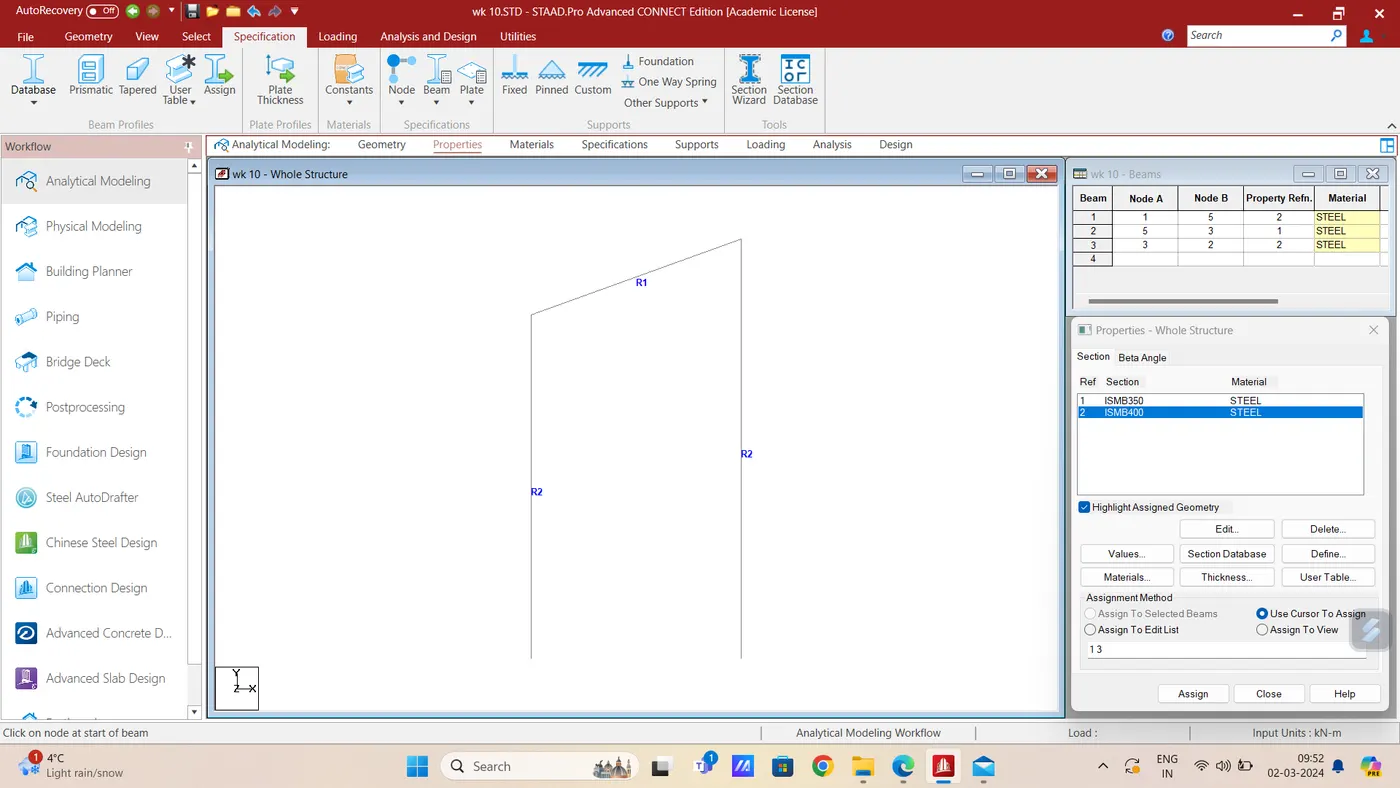
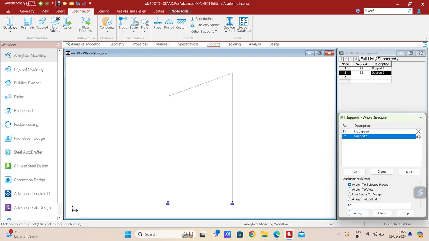
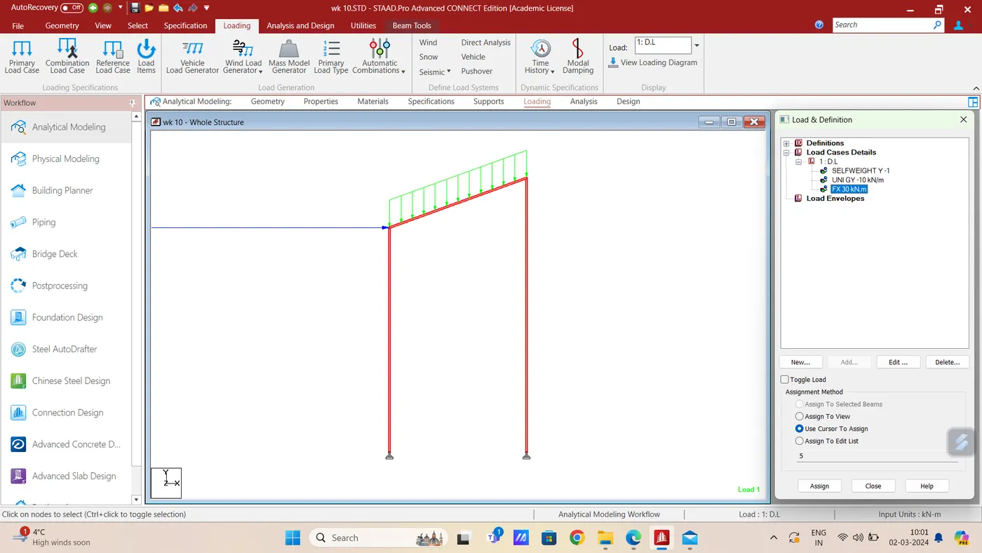
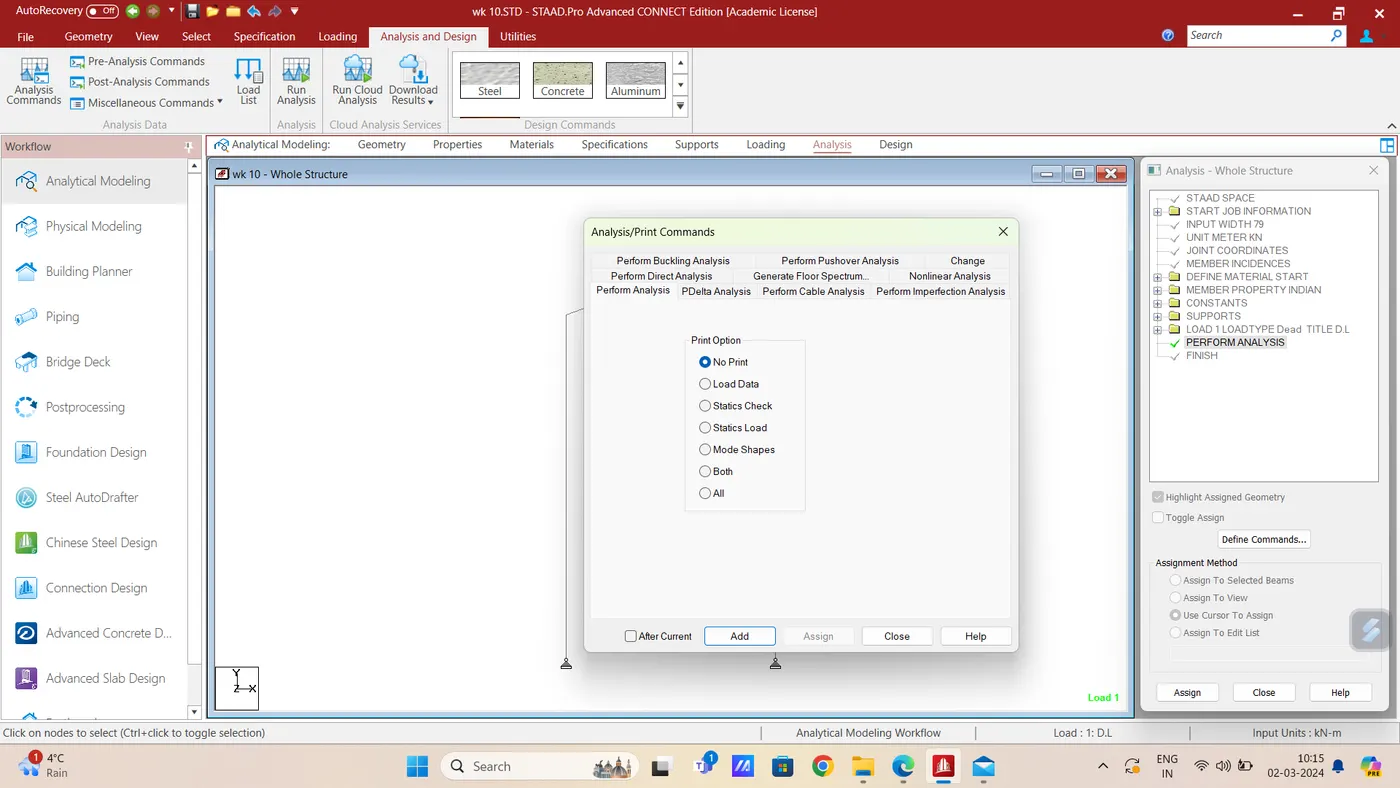
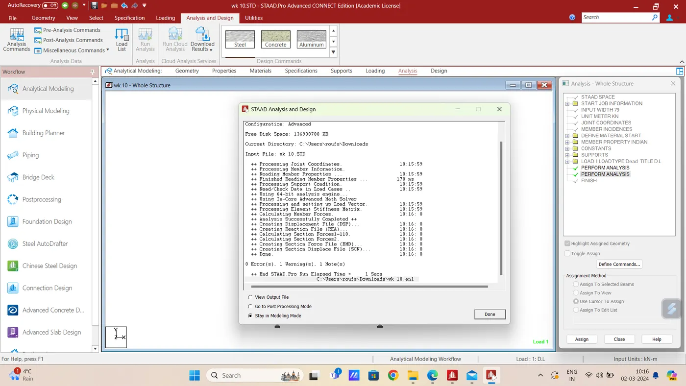
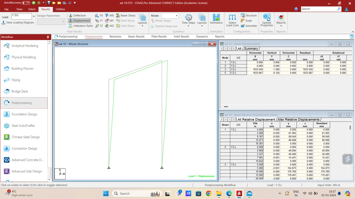
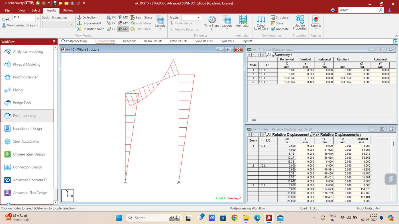
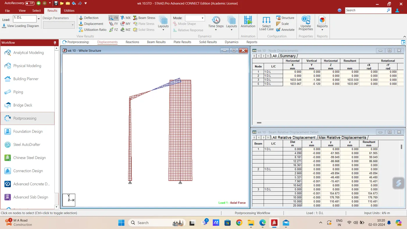
Figure 3)
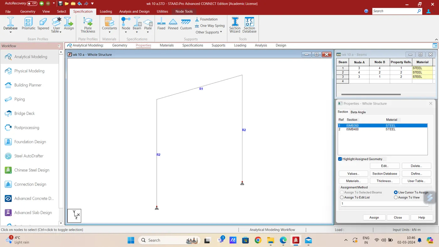
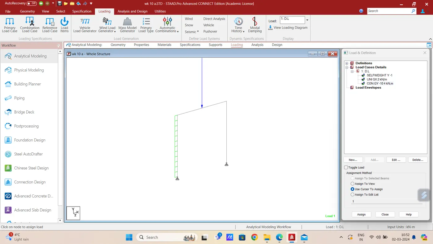
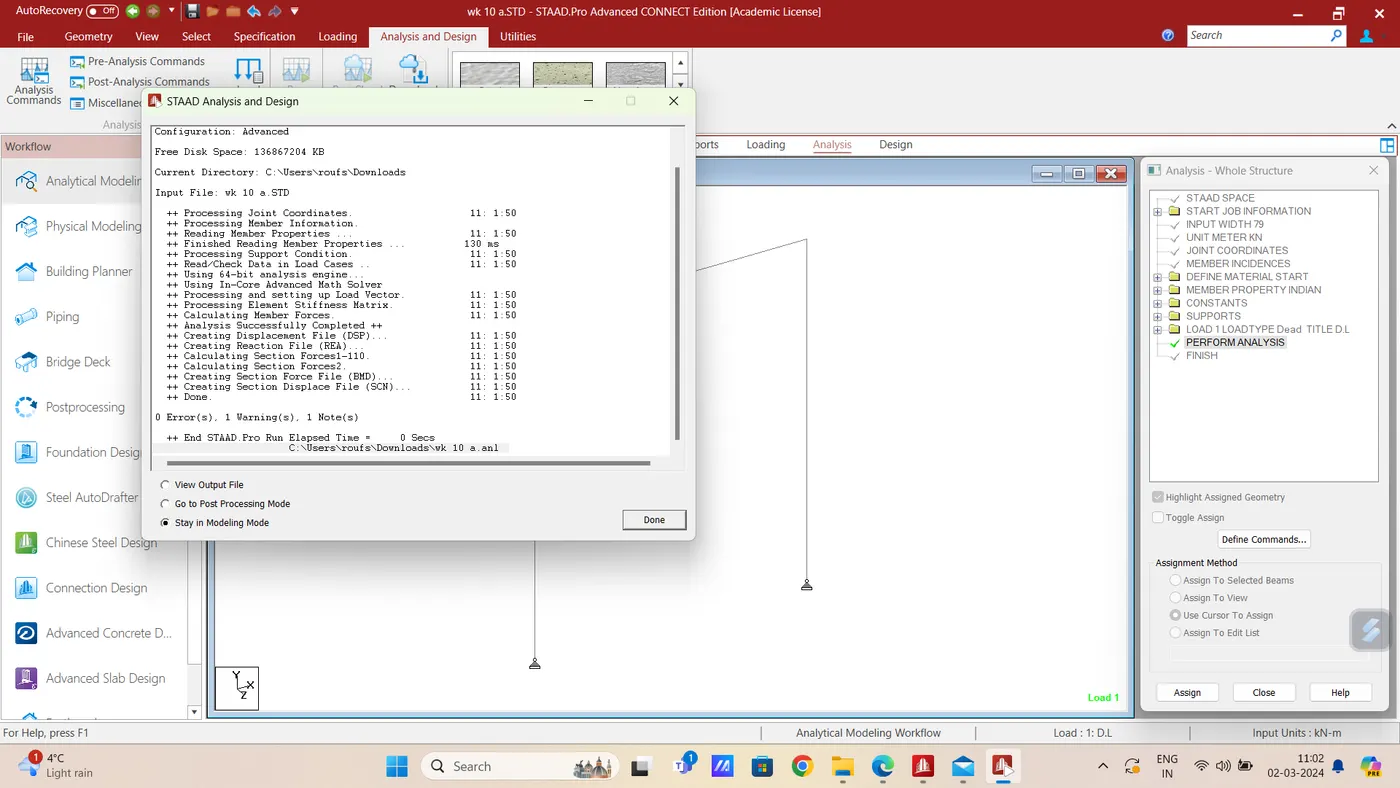
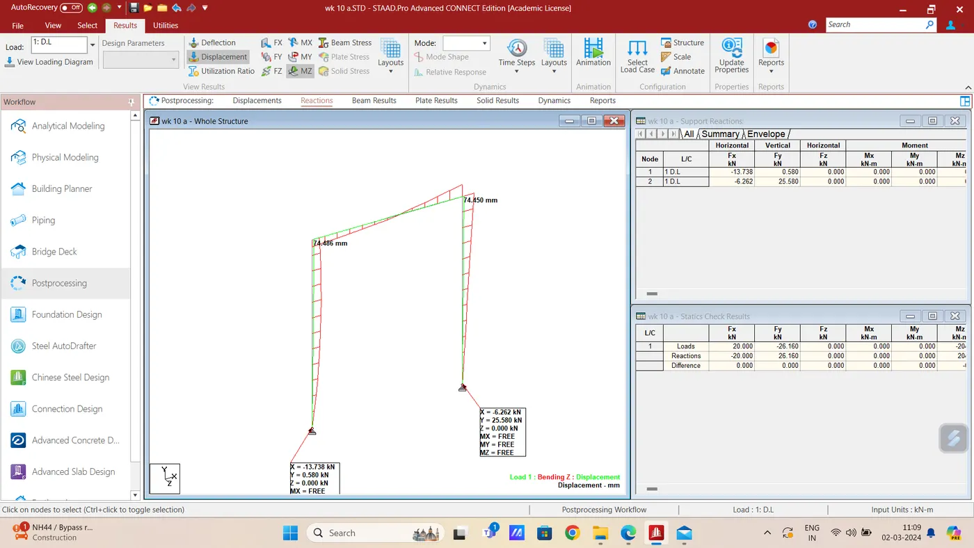
3. Deflection of a frame, present result from STAAD.Pro
1) Aim & Introduction- Lateral deflection at point A and vertical deflection at mid section of Beam between B & C from figure-1 in previous chaalenge i.e. challenge-2 ( Fig-1) are required to be determined.
Procedure-
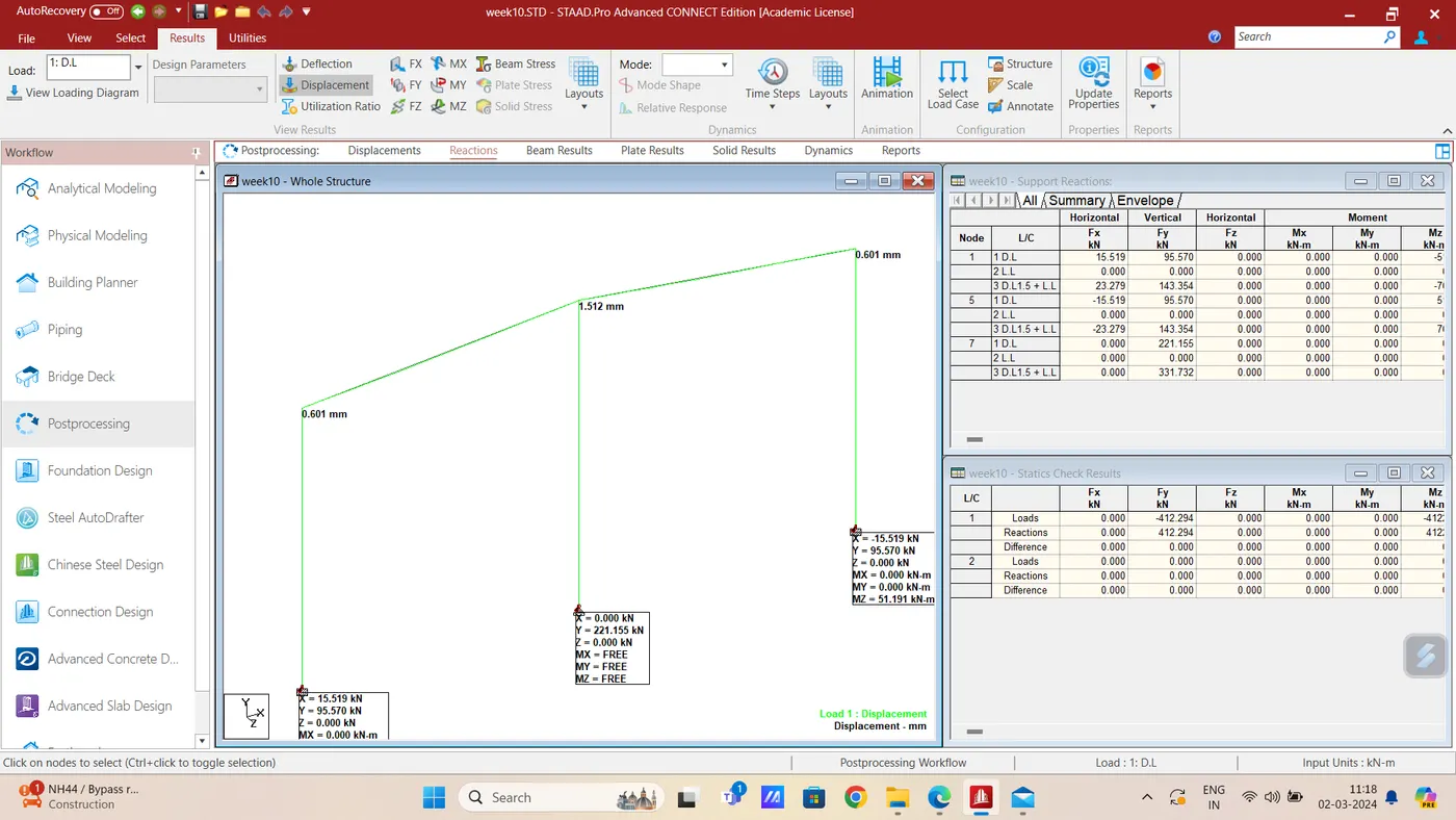
With the model of challenge-2 ( Fig-1) using Run Analysisi command in the Analysis and Design option then in the Post Processing option displacement command for load combination case-3 give the maximum deflection as shown below-
Deflection at A is 0.727 mm as shown in the print screen given below-
Max deflection at mid point of beam between B & C is 22.626 mm as shown below
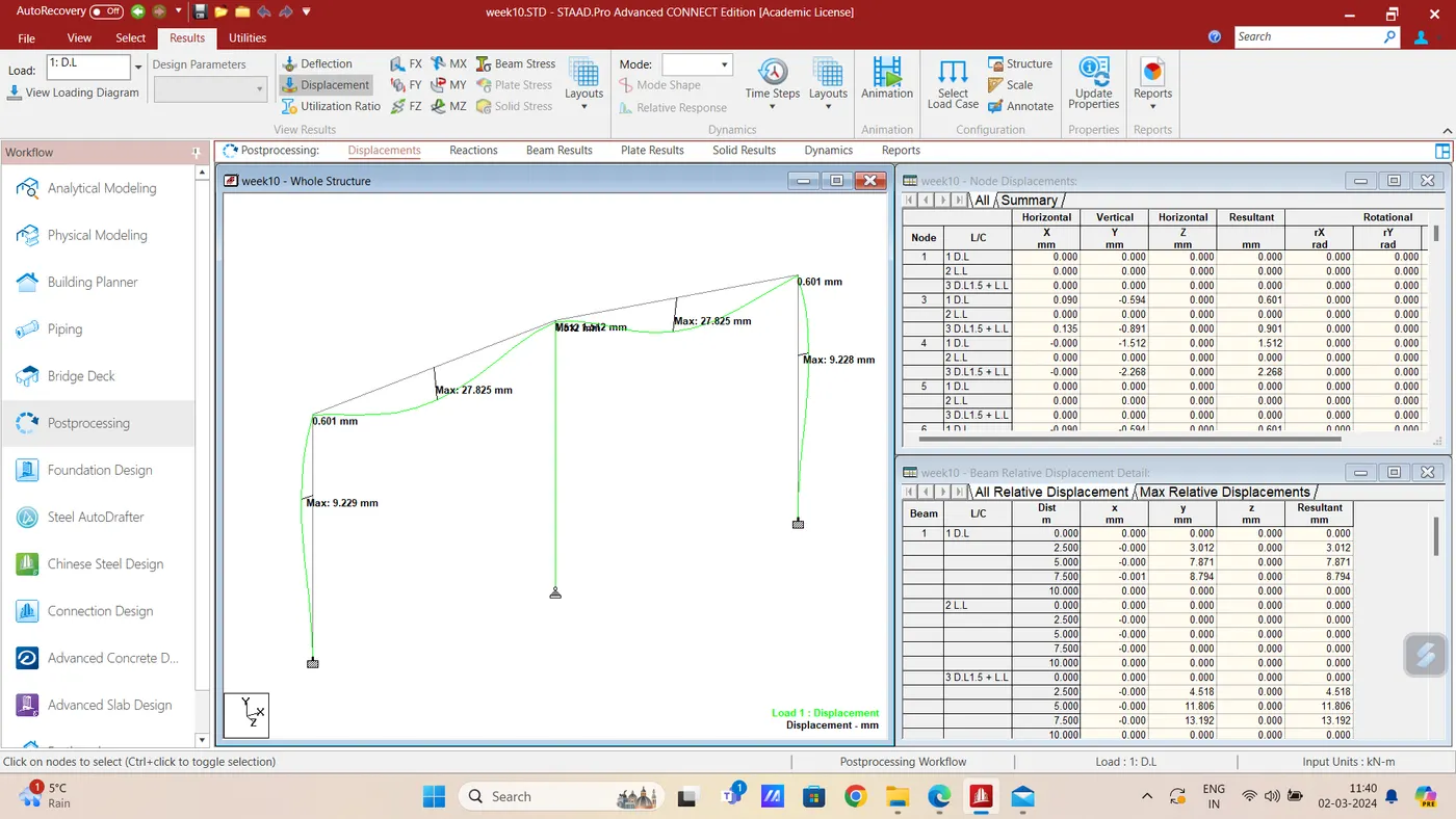
vStaat.Pro file is already attached against Challenge-2 through which max deflection ( Load case-3) can be viewed using deflection command in the Post Processing after performing Run Analysis command in Analysis and Design.
Result: it is concluded that the deflection at point A = 0.601 mm & at mid point of beam between B & C is 27.825 mm
Q-3(2) Aim & Introduction- Lateral deflection at point A and vertical deflection at mid section of Beam between A & B from figure-1 in previous chaalenge i.e. challenge-2 ( Fig-2) are required to be determined
Procedure-
With the model of challenge-2 ( Fig-2) using Run Analysisi command in the Analysis and Design option then in the Post Processing option displacement command for load combination case-3 give the maximum deflection as shown below-
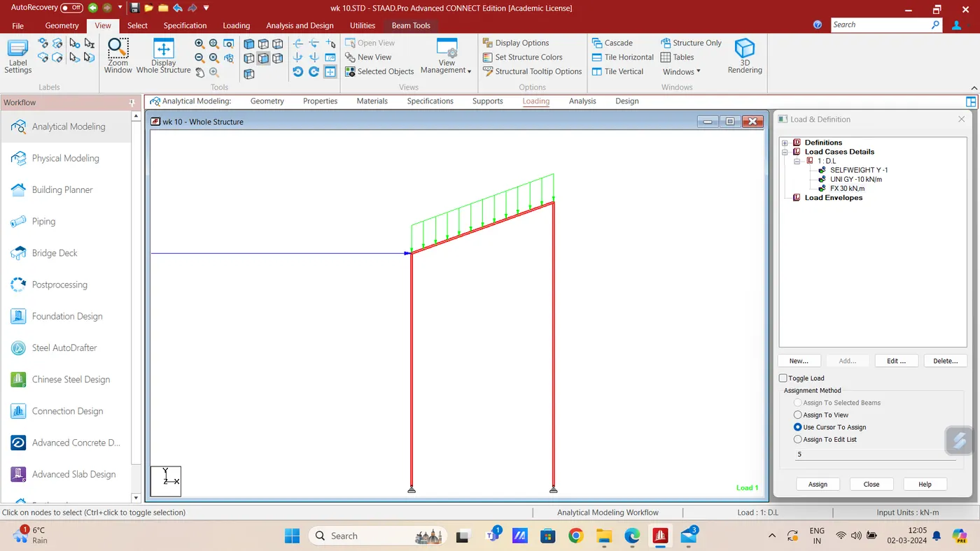
Deflection at A is 931.174 mm as shown in the print screen given below-
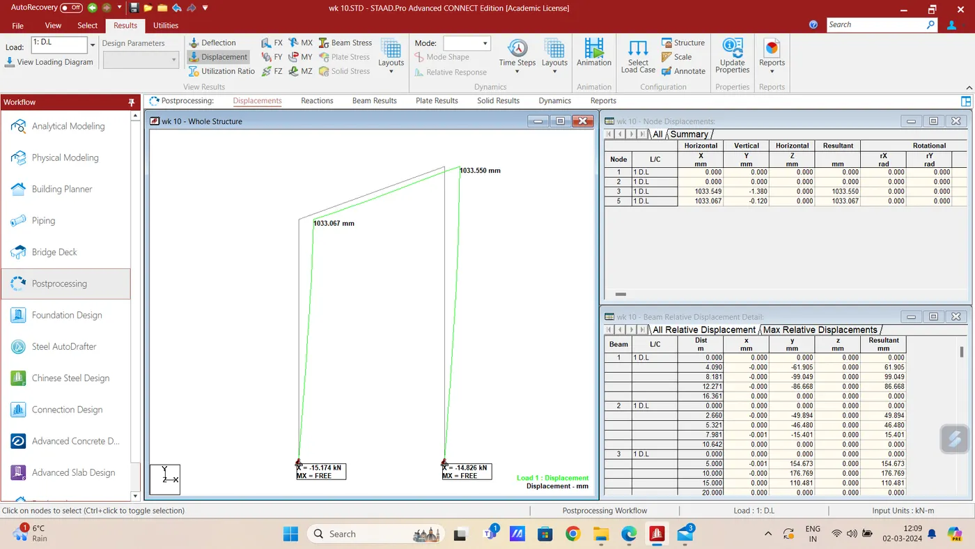
Max deflection at mid point of beam between A & B is 629.147 mm as shown below-
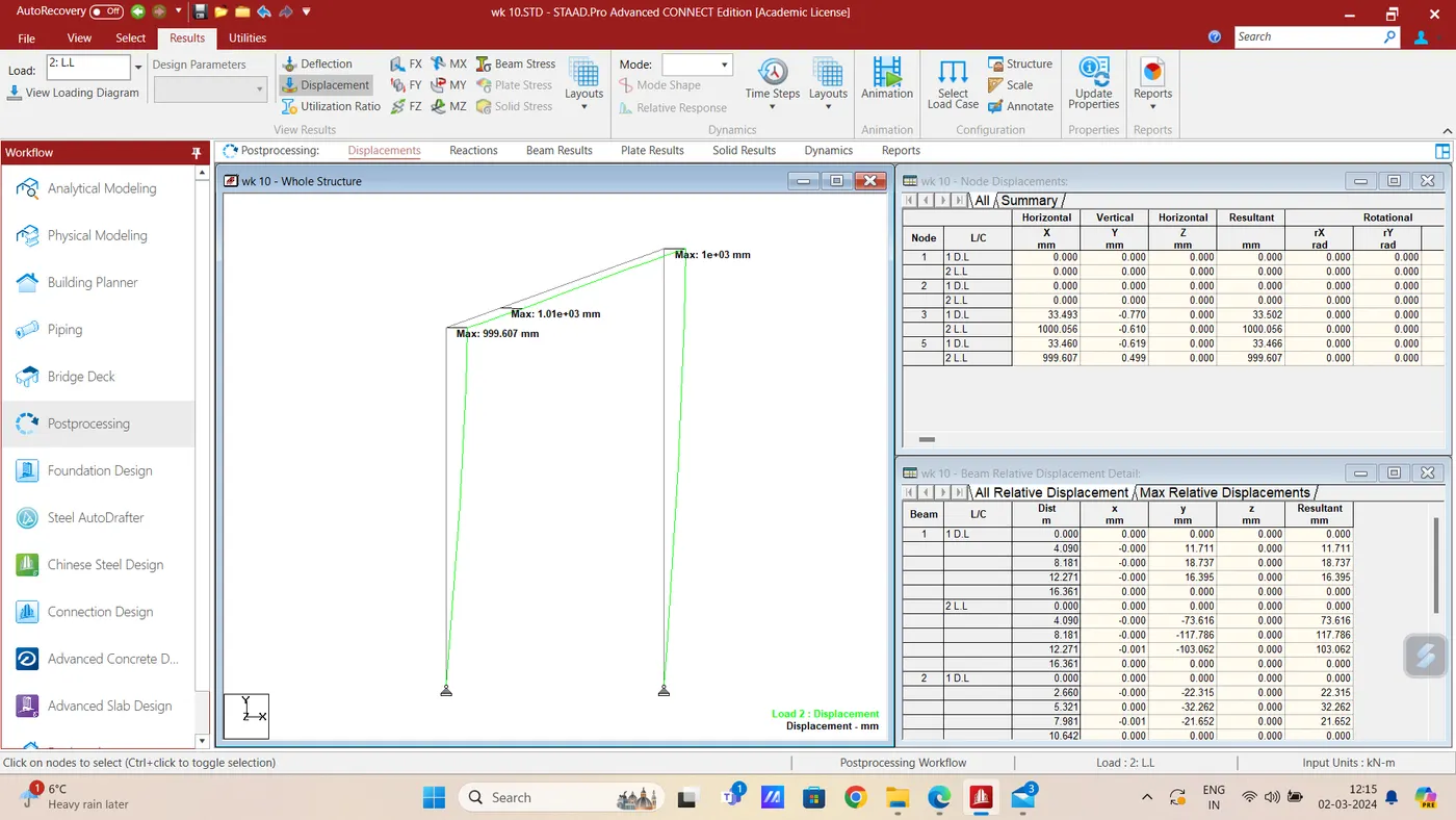
Result: it is concluded that the deflection at point A = 999.607mm & at mid point of beam between B & C is 629.147 mm
Q-3(3) Aim & Introduction- Lateral deflection at point A a & B from figure-3 in previous chaalenge i.e. challenge-2 ( Fig-3) are required to be determined
Procedure-
With the model of challenge-2 ( Fig-3) using Run Analysisi command in the Analysis and Design option then in the Post Processing option displacement command for load combination case-3 give the maximum deflection as shown below-
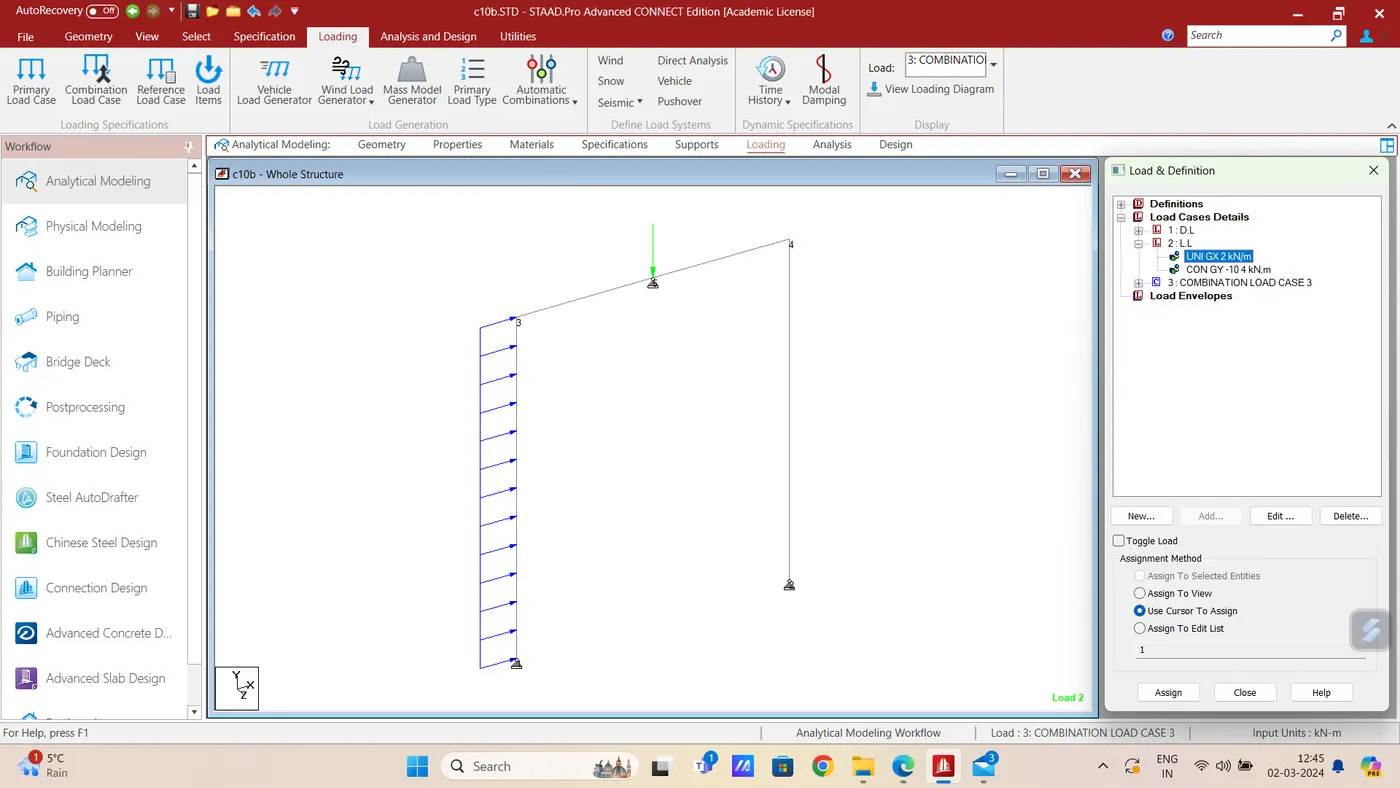
Deflection at A along X Axis = 0.052 , Along Y Axis = 0.079 mm and Resultant displacement is 0.11 mm as shown in the print screen given below-
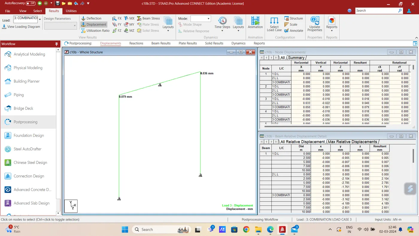
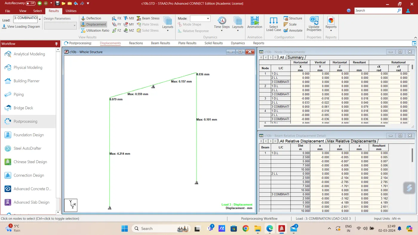
Result: it is concluded that the Ressultant deflection at point A = 0.079mm & at B is 0.00 mm