Week 9 Challenge
Mold design - CPU fan case
MOLD DESIGN & SLIDERS CREATION FOR Mold design - CPU fan case SOLIDWORKS
The report details the process of designing and creating molds for the sliders of a CPU fan case. Each part was created in the assembly workbench, following a step-by-step process to achieve the best results. In order to create the necessary sliders, inserts were also made. Assuming that the material used for the model is ABS (with shrinkage of 0.6%), the scale value is determined to be 1.006 for the model.
MODEL
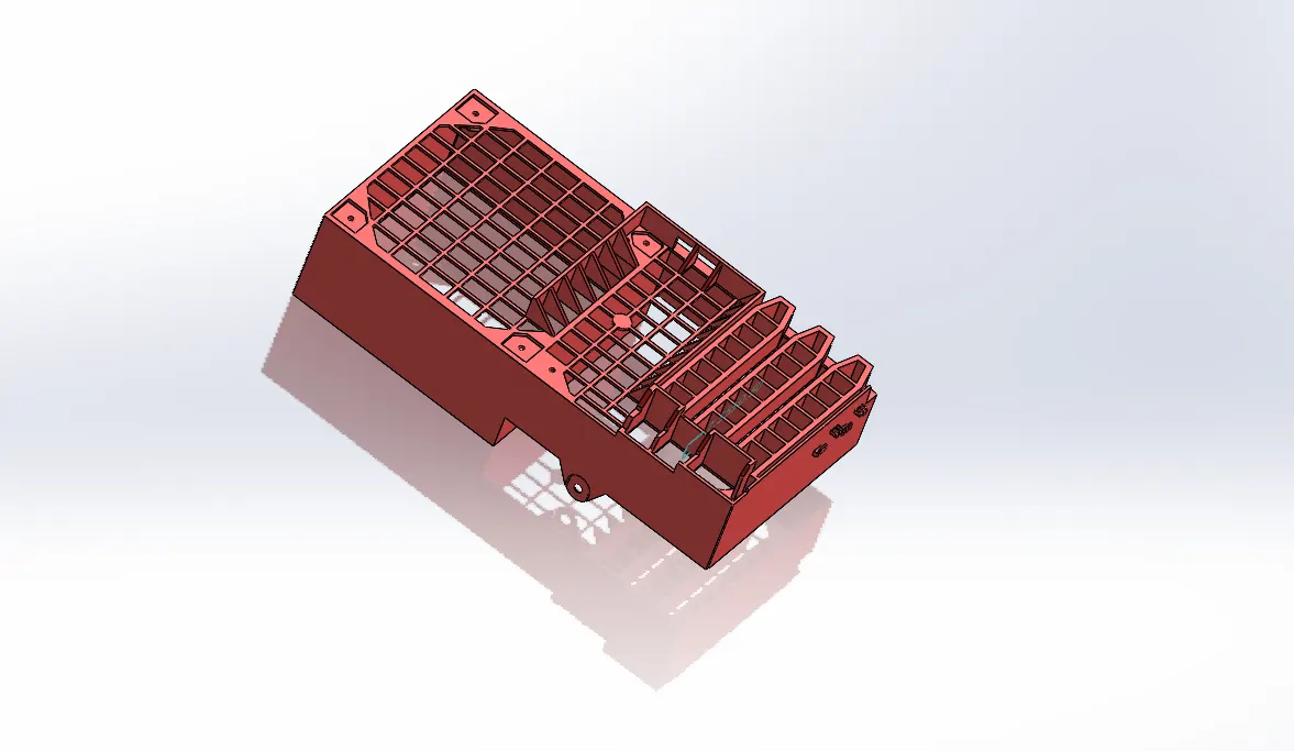
Please find below the steps and commands used for creating the core and cavity blocks:
MOLD TOOLS
• Mold Pull direction:
This refers to the direction in which the core moves away from the mold. The direction of pull is determined based on the models and features present in the model.
• Draft Analysis:
The draft angles of faces are analyzed based on the mold pull direction to ensure that the core and cavity blocks can be separated easily.
• Draft Analysis for Slider:
The draft angles of faces are analyzed based on the slider direction to ensure that the slider can move smoothly.
• Draft Creation:
A minimum draft of 0.5 degrees is required for the component. If there is no draft available, a certain draft will be provided to the component.
• Scale:
The model is scaled by a specified factor based on the material provided (shrinkage factor).
• Parting Line:
The parting line separates the core and cavity surfaces.
- Shut of Surfaces:
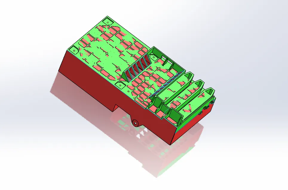
To manufacture a mold for a car door bezel, we need to create mold shut-off surfaces that prevent injected material from flowing. This is done by creating shut-off surfaces. In addition, we should create parting surfaces between core and cavity surfaces to ensure smooth operation.
- Parting Surface:
Create parting surfaces between core and cavity surfaces.
- Core & Cavity Blocks:
We'll create the core and cavity block as separate parts in the assembly by inserting the component as core and cavity surfaces. The sprue location will be adjusted by rotating and giving mates with the assembly planes.
1.Core
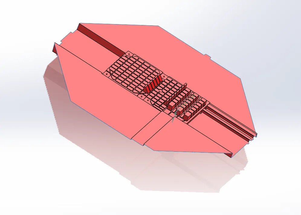
The core block is made using the core surface created. There will be two blocks in total - an internal block and an external block, which are created by considering the minimum distance between the mold and the outer edge, as well as the base of the slider. These two blocks act as a single core block, as they are due to a curvature in the parting line.
2. Cavity
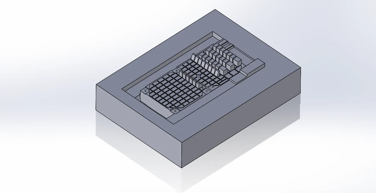
The cavity block is created using the cavity surface created and there will be 2 blocks internal and external block which are created considering the minimum distance between mold and the outer edge and the base of slider these two blocks are due to a curvature in parting line and combinedly these two blocks act as single cavity block
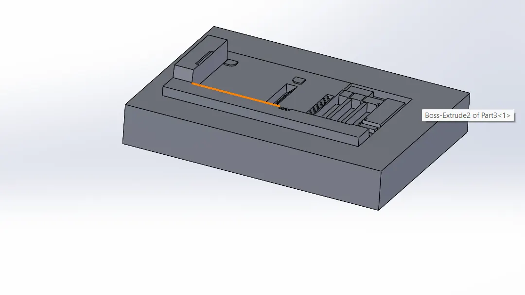
During the mold design of the CPU fan case in the step of draft analysis we can observe an undercut is present, to optimize the undercut sliders will be used.
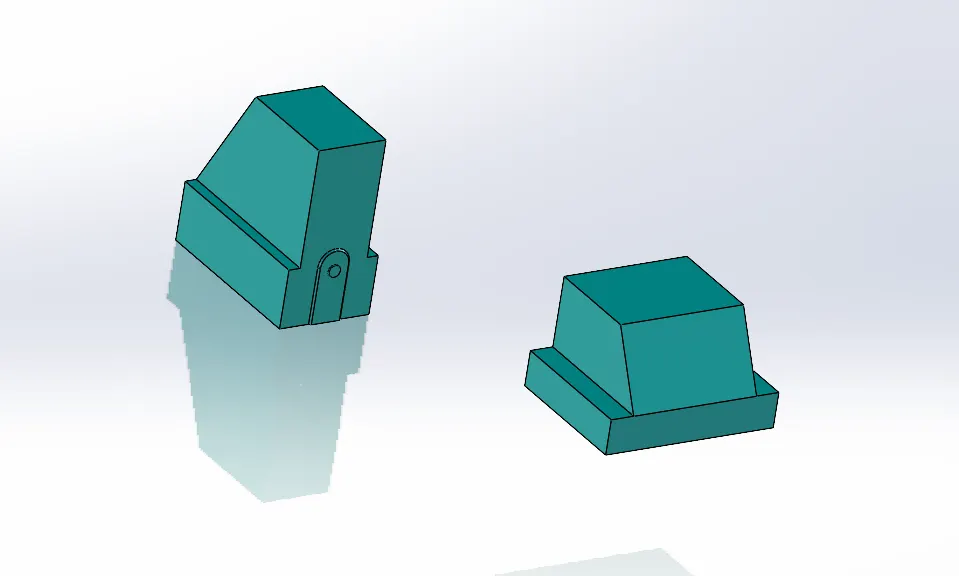
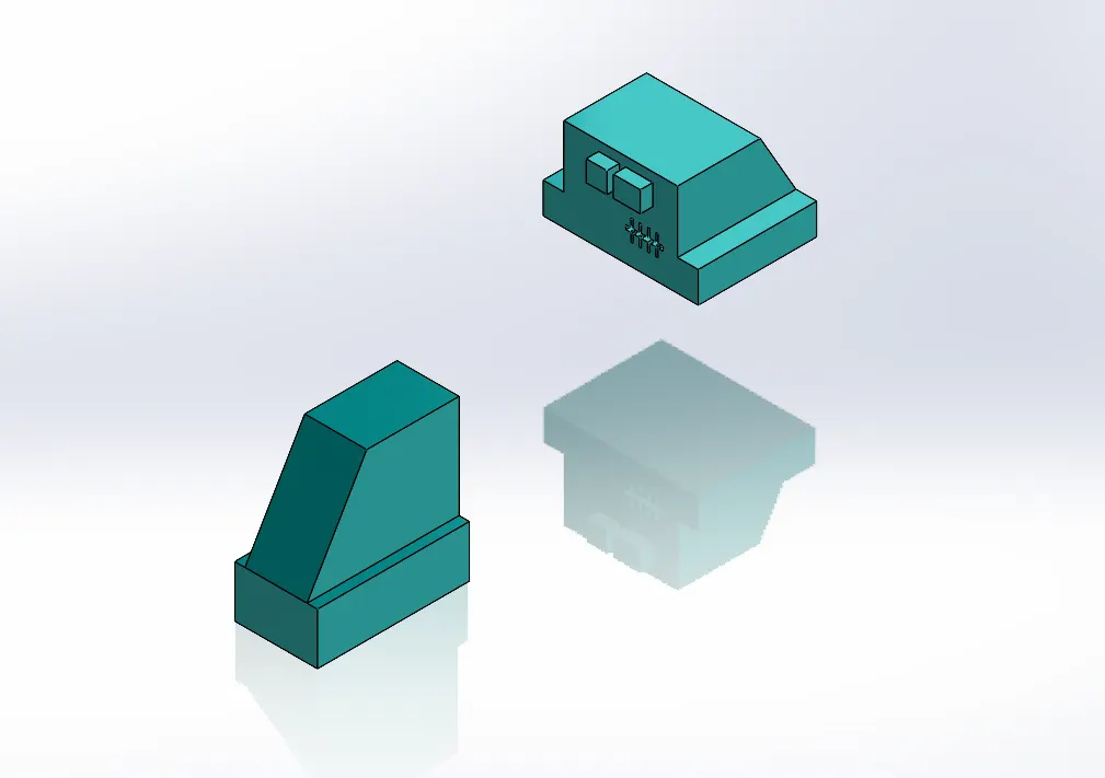
The slider direction will be perpendicular to the direction of the pull which will be horizontal and these are separable from the core and cavity blocks as the sliders are movable, they should have a base for the movement from the model we can easily provide a base while creating the blocks itself, and as the undercuts will be the slots the sliders are designed in a manner that they will be able to close the slots with an extruded shape of the slots.
The commands and steps involved in the creation of the slider are:
SLIDER CREATION:
The commands used for the creation of sliders are:
- REFERENCE PLANE:
This command is used to create a plane, or axis.
- SKETCH:
Using this command, we can create a new sketch.
- CONVERT ENTITIES:
It is a tool available in the sketching workbench to project the sketch selected on the plane you are sketching and in this tool another option of intersection curve is there which is also used to project sketch.
- SPLIT:
It is available in the features tab used to split the body in two pieces along the sketch based on applications.
- FILLETS
It is used to make fillets to the edges of solid bodies.
- RECTANGLES:
It is also an entity used and available in sketching workbench to create a rectangle of different types like corner rectangles, center rectangle, 3-point corner rectangles, 3-point center rectangle, and parallelograms based on their applications.
- CUT EXTRUDE
It is available in features tab used to remove material from a solid body along the sketch in which direction, we need based on applications.
- EXTRUDE BOSS
It is available in features tab used to add material from a solid body along the sketch in which direction, we need based on applications.
- MOVE FACE
It is available in mold tools tab used to move faces of a solid body.
- MOVE/COPY BODIES
It is available in mold tools tab used to moves, copies and rotate solid and surface bodies.
- COMBINE
It is available in mold tools tab used to add, subtract bodies.
- DELETE/KEEP BODY
It is available in mold tools tab used to keep or delete a solid body or surface body.
Identification of Undercuts
Identified two specific undercuts in the CPU fan case model where sliders are required for the molding process.
Understood the geometry and complexity of these undercuts to determine the type and design of sliders needed.
Slider Design
Determined the type of sliders required for each undercut. Sliders are components that allow the mold to open and release the part by sliding out of the way of undercuts.
Designed two sliders, one for each undercut, ensuring that they fit seamlessly into the mold and provide adequate clearance for smooth ejection.
Insert Design
Identified areas in the mold where inserts are required for adding details or improving the mold's functionality.
Designed inserts for those areas, ensuring they are seamlessly integrated into the mold blocks.
Material Selection
Selected appropriate materials for sliders and inserts, considering factors such as wear resistance, durability, and compatibility with the molding process.
Modeling Sliders and
Used CAD software to model the sliders and inserts, ensuring precision in dimensions and alignment with the existing mold blocks.
Paid attention to draft angles, clearances, and parting lines to facilitate smooth assembly and disassembly of the mold.
Compatibility Check
Inserts
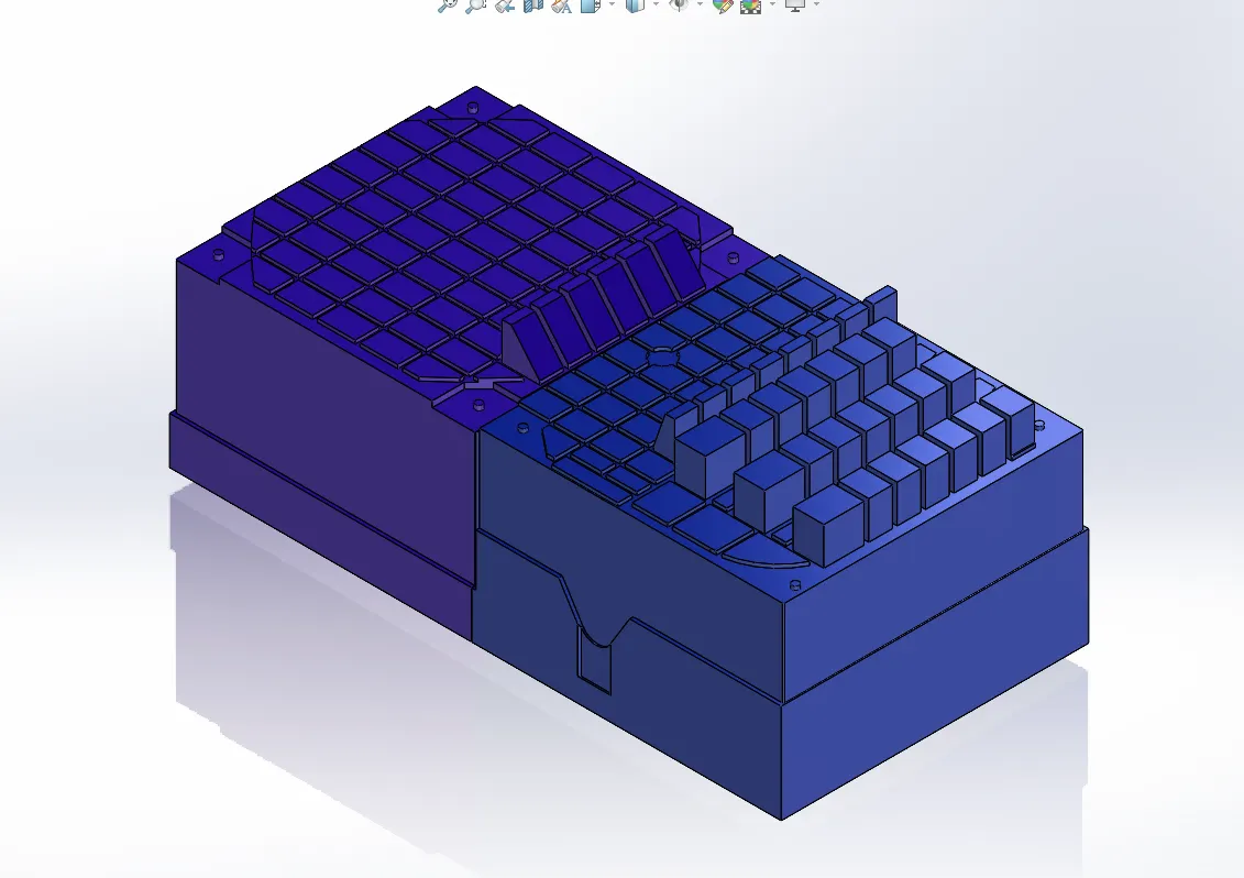
what is Insert Design
Insert design in the context of mold design refers to the incorporation of additional components, called inserts, into the mold structure. These inserts serve various purposes and are strategically placed within the mold cavity or core to enhance the functionality, features, or ease of manufacturing. Here are some common reasons for incorporating inserts in mold design:
Adding Details or Features:
Inserts can be used to add intricate details or features to the molded part that may be challenging to achieve solely through the mold's core and cavity. This is particularly useful for parts with complex geometries or fine details.
Material Enhancement:
Inserts allow for the use of different materials in specific areas of the mold. For instance, an insert made of a wear-resistant material can be placed in high-wear regions to increase the lifespan of the mold.
Facilitating Multi-Material Molding:
In cases where a molded part requires different materials in different sections, inserts can be employed to define those areas. This is common in multi-material or overmolding processes.
Simplifying Mold Maintenance:
Inserts can be designed to be replaceable, making mold maintenance more straightforward. If a part of the mold becomes worn or damaged, only the insert needs to be replaced rather than the entire mold block.
Threaded Inserts for Fastening:
Molded parts may require threaded holes for assembly. Threaded inserts can be incorporated into the mold design to provide accurate and consistent threads in the molded part.
Core-Pulling Mechanisms:
Inserts are often used in molds with core-pulling mechanisms. These mechanisms are required when features such as undercuts are present in the part design. Inserts facilitate the creation of these undercuts by moving with the core during ejection.
Temperature Regulation:
Inserts can be used for incorporating temperature control channels, allowing for better regulation of the mold temperature during the injection molding process. This is particularly important for achieving optimal part quality and reducing cycle times.
Insert design involves careful consideration of the mold's overall functionality, the requirements of the molded part, and the materials and processes involved in the injection molding. It requires precision in the placement and integration of inserts to ensure seamless operation during the molding process.
Step 9: Submission
Prepared a comprehensive report summarizing the steps taken, challenges faced, and solutions implemented during the design of sliders and inserts for the CPU fan case mold blocks.
Compiled all necessary files, including CAD files, drawings, and the report, for submission.
By following these steps, I ensured the successful integration of sliders and inserts into the CPU fan case mold blocks, enhancing the mold's functionality and efficiency in the injection molding process.
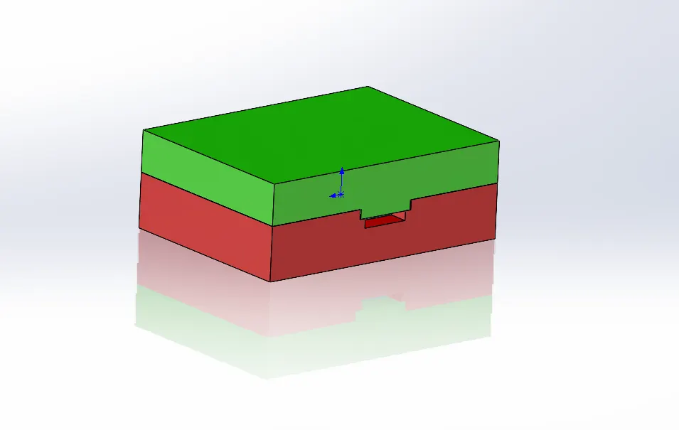
The final mold design with sliders and locking mechanism created will be:
referencance by chat gpt