Week 9 - Challenge 2 - Switch Bezel Design
Aim :
create the switch bezel component through the given class A surface and perform the draft analysis of the model
thickness of the plastic part 3.0mm
objectives:
- create a tooling axis
- generate class B and class C surfaces from the class A surface
- convert the surface in to a solid body
- use publication option to publish
- tooling axis
- class A, B and C surfaces
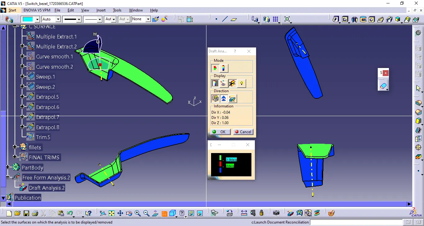
- draft analysis of class A and final surface
introduction :
this project involves creating a switch bezel part from a class A surface . steps include crating a class B surface with a 3.0mm thickness and class C surface derived from the class A surface
class A surface :
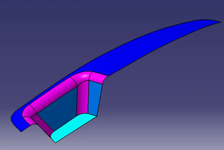
the class A surface is primary reference surface in vehicle design , used to create the Class B surface
tooling AXIS :
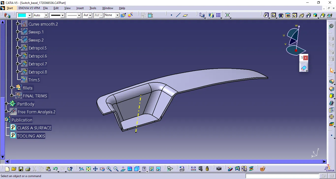
the tooling axis defines the direction used in the manufacturing process to create components with a positive draft angle , ensuring the component meets design requirements
creation of the tooling axis:
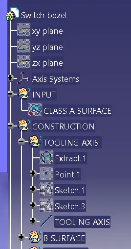
in this project , the tooling axis is created using the intersect the 3D elements method:
1. create a point at the centre of the surface of the class A interests
2. create a line in YZ axis, then draw a lines on the walls and make a centre line
3. Then make a centre line by bisecting line
4. Create a another sketch in ZX axis, cut part by sketch plane with that axis
5. Draw a line on the intersect part, then draw line on the centre of axis then constraint them with 6degree
6. bisect lines with YZ nd ZX axis with respected point, one centre shows that's the main tooling axis
7. the bisection lines represents the tooling direction of the component , which is known as the tooling axis . it indicates the direction of the tool used in the components manufacturing process
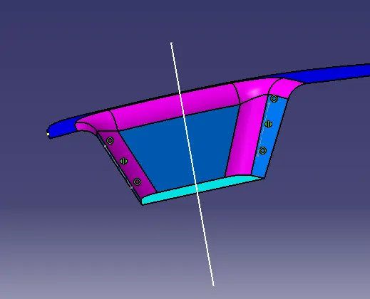
The picture shows the yz axis line
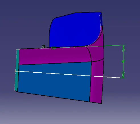
the picture shows the ZX axis line
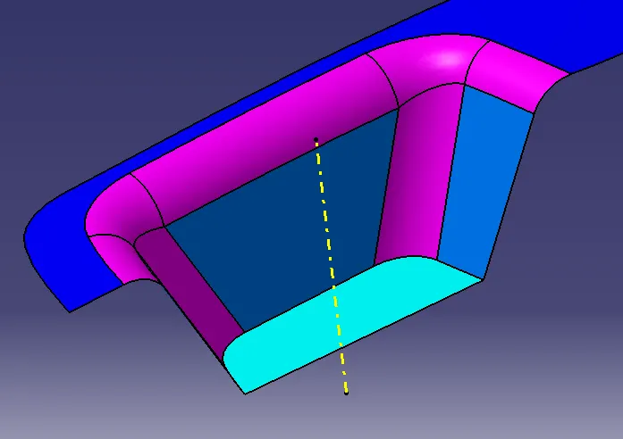
the yellow color lines represents the tooling direction of the component , which is known as the tooling axis . it indicates the direction of the tool used in the components manufacturing process
class B surface :
the class B surface , also called the engineering surface , is created from the class A surface with the component thickness
creation of the class B surface :
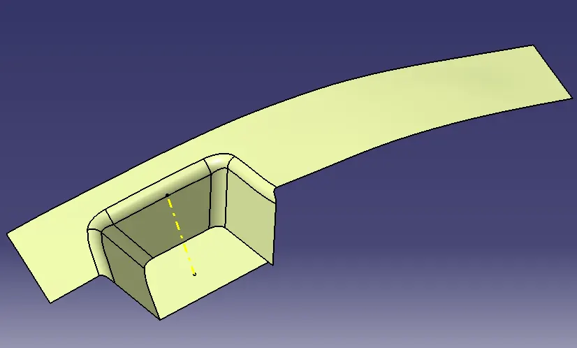
class B surface is generated by extracting the class A surface and offsetting it by the component thickness (3.0mm) .
steps to create class B surface :
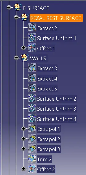
1. extract the top surface untrim the surface, and extrapolate with 20mm, offset with 3.0mm
2. extract the walls untrim the surface, and extrapolate the edges with 20mm, then offset 3.0mm
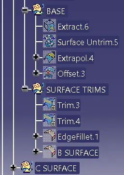
3. extract the Base untrim the surface, and extrapolate the edges with 20mm, then offset 3.0mm
4. Trim the surfaces and add fillets to them
5. create edge fillets based on the class A surfaces
for the external fillets , use fillet radius + thickness
for the internal fillets, use fillet radius - thickness
the result is trimmed and filleted as B surface
Class C Surface:
The Class C surface connects the Class A and Class B surfaces.
Creation of Class C Surface:
Class C surface is created by:
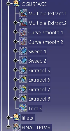
1. Extracting the edges from the Class A surface.
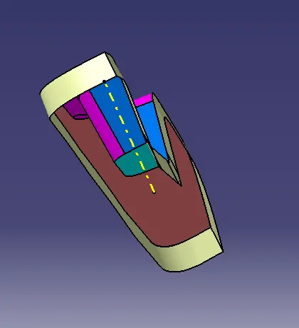
2. Sweeping the extracted edges and holes along the Tooling Axis, applying a 3-degree draft angle towards the Class B surface Together, these surfaces form the Class C surface.
Final Trim:
Combine the Class A and Class C surfaces using the Join command.
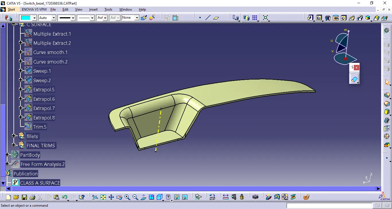
Trim the Class A and Class C surfaces with the Class B surface to obtain the final surface of the component.
Switch to the Part workbench and use the Closed Surface tool to convert the closed surface of the component into a solid part.
DRAFT ANALYSIS:
Draft analysis is used in CAD (Computer-Aided Design) software to ensure that a part can be easily removed from a mold during manufacturing process in injection molding
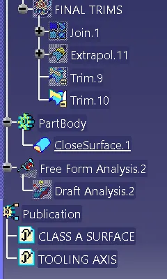
TREE STRUCTURE