Week 9 - Challenge 1 - Base Bracket Design
Week 9 - Challenge 1 - Base Bracket Design
Here in this exercise, I experienced the draft analysis and tooling direction, so let me explain those.
1. TOOLING AXIS
- The Tooling axis also called the intersection axis or pulling direction, is the direction in which a part is removed from a mold or die during the manufacturing process in injection molding
- It represents the main direction of movement of the mold core or cavity
- It helps define how much draft is needed on a vertical surface
- Draft analysis is the process of evaluating a 3D CAD model to determine whether it has adequate draft angles and slight tapers on vertical walls relative to the tooling axis
- Draft angles help parts release easily from the mold.
- CAD software typically uses color coding to highlight areas: eg, green for correct draft, red for negative draft, and blue for zero draft
Here I attached the pics of the draft analysis of the exercise.
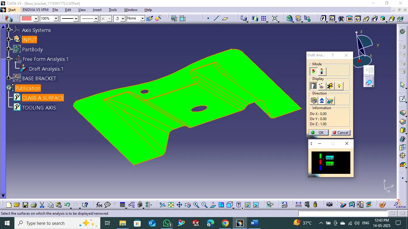
This is the screenshot of the draft analysis for the CLASS A SURFACE
In this picture, u can see the green color is correct draft.
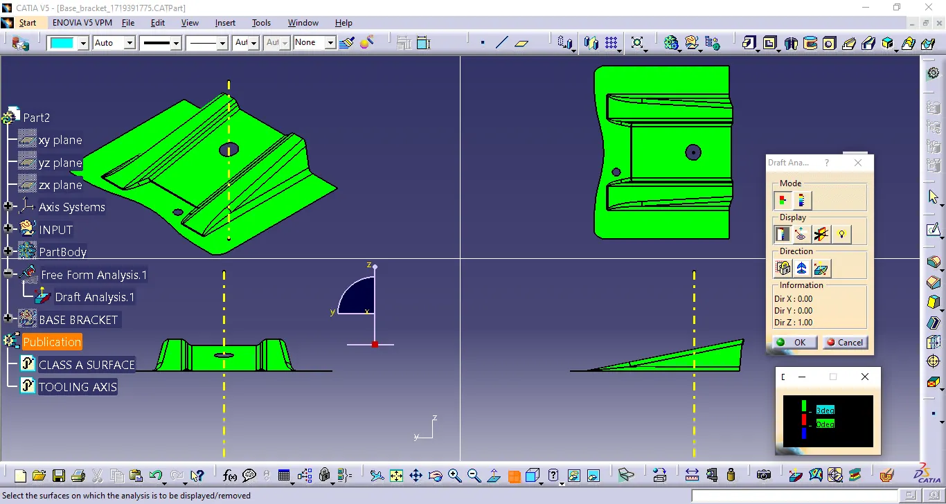
Here I attached the pic of TOOLING AXIS.
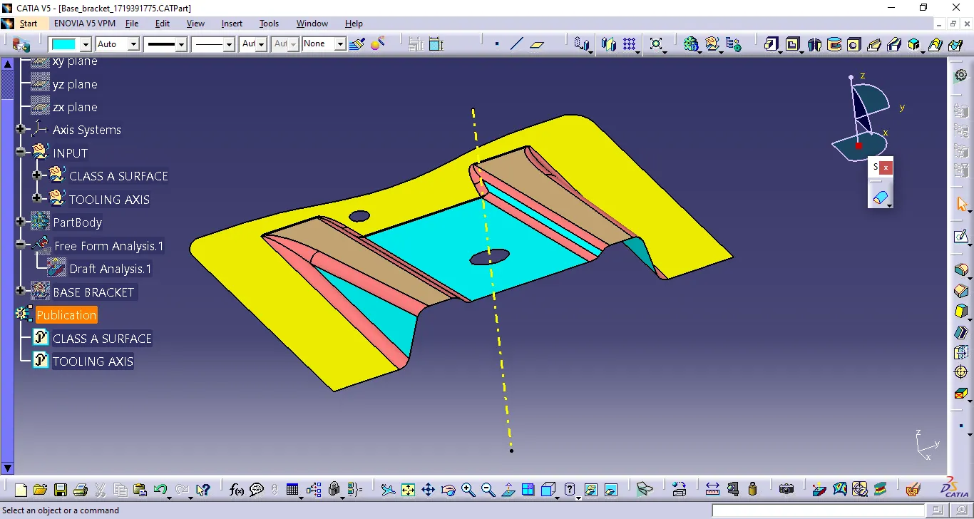
In the screenshot, u can see the yellow color line is tooling axis.
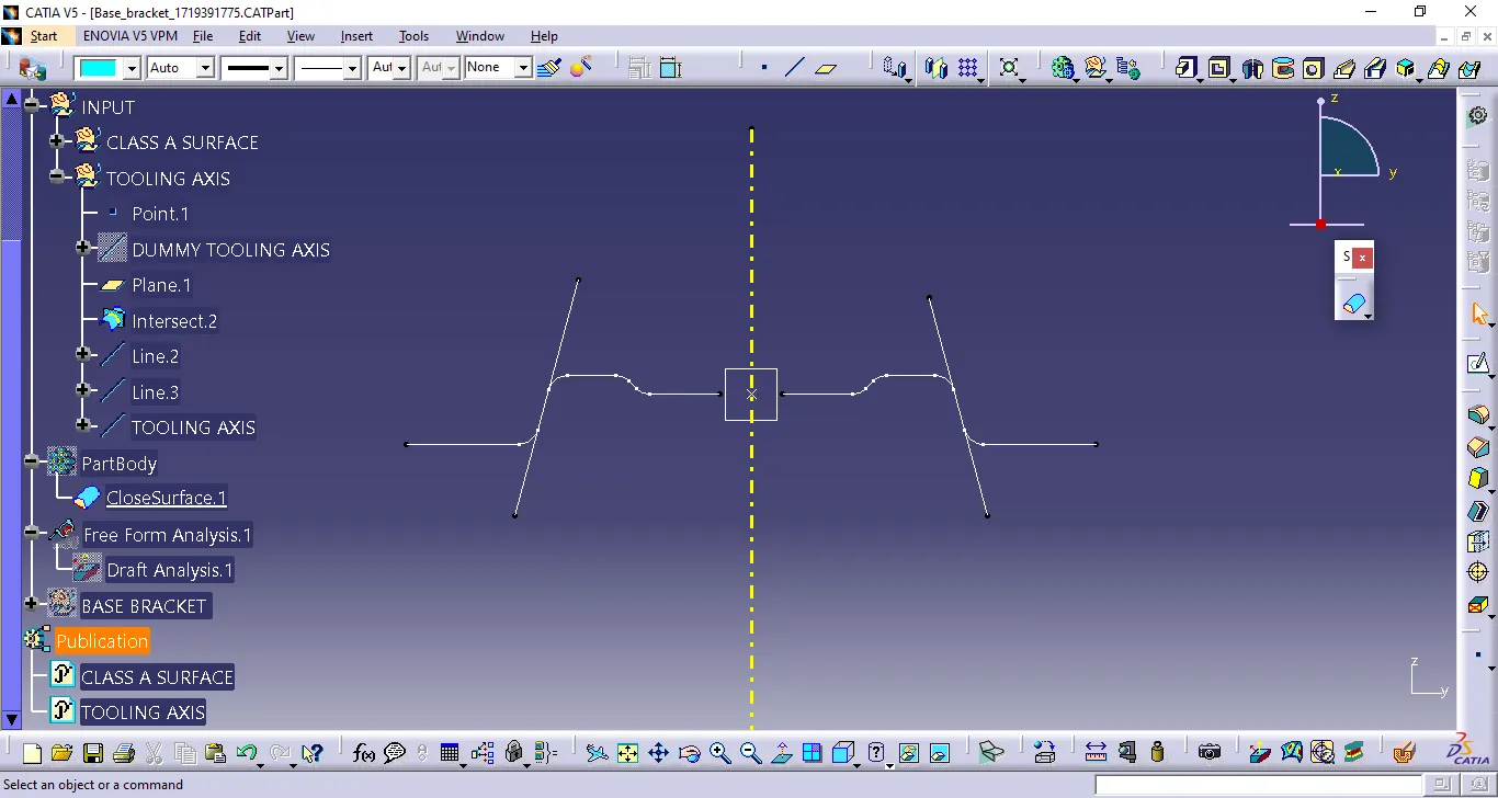
To create a tooling axis, u must create the dummy axis first, then, by using the intersecting command with respect to the plane, draw the line on the respective point, then using the bisecting line command with a point
Here, the attached shows how i created the tooling axis