Week 9 - Challenge 2 - Switch Bezel Design
Switch Bezel Design
AIM:
Create the switch bezel plastic component using the given Class-A surface and perform a draft analysis on the part.
OBJECTIVE:
- To create a Tooling Axis on Class-A Surface Using Bisecting method.
- To create Class B & C surfaces from the parameters: Thickness 2.5mm, minimum draft angle 3degrees.
- To join Classes A, B &C, use the Join and Trim Command to remove excess material and best fit of the surfaces
- Then, define the part body using the Closed Surface command in Part Design. A solid body should create the components.
- Finally, a draft analysis of the final component will be performed.
INTRODUCTION:
The control panel bezel is the frame part of the window switch that holds its switch covers and buttons in place. Most OEMs use moulding to manufacture the plastic trims of automotive vehicles; hence, the switch bezel is designed with this in mind.
Class-A Surface:
Class A surfacing refers to creating high-quality, freeform surfaces with styling intent that are visible and touchable, often used in automotive and other industries demanding aesthetic precision.
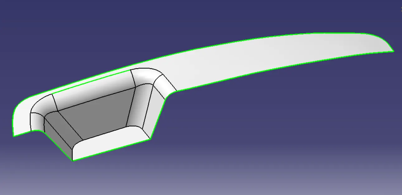
The following surface is given as the input for creating the part. This will be the leading aesthetic surface for the switch bezel.
Tooling Axis:
The tooling axis is the direction in which the mold pulls apart. It is necessary to create a tooling axis to give a draft to the component. The tooling axis is created using the Bisecting Method for the given class A surface. The best tooling direction for the component is chosen by considering the tooling of the final product. It is chosen in such a way that the component is cleared with minimum tooling.
Creation of Tooling Axis:
- We extract the base body and origin point and create an axis system to help with the creation of tooling axis.
- Intersecting the given class A surface in yz plane, an outline sketch is obtained. Bisecting the critical lines of the obtained sketch to get tooling direction in yz plane, similarly obtain the tooling direction in zx as well keeping the draft angle more then 3°.
- Using the obtained tooling axis, bisect this axis and create a main tooling axis, and check for the suitability of the tooling axis by visually confirming that all surfaces of class A are visible from the direction normal to the main tooling axis.
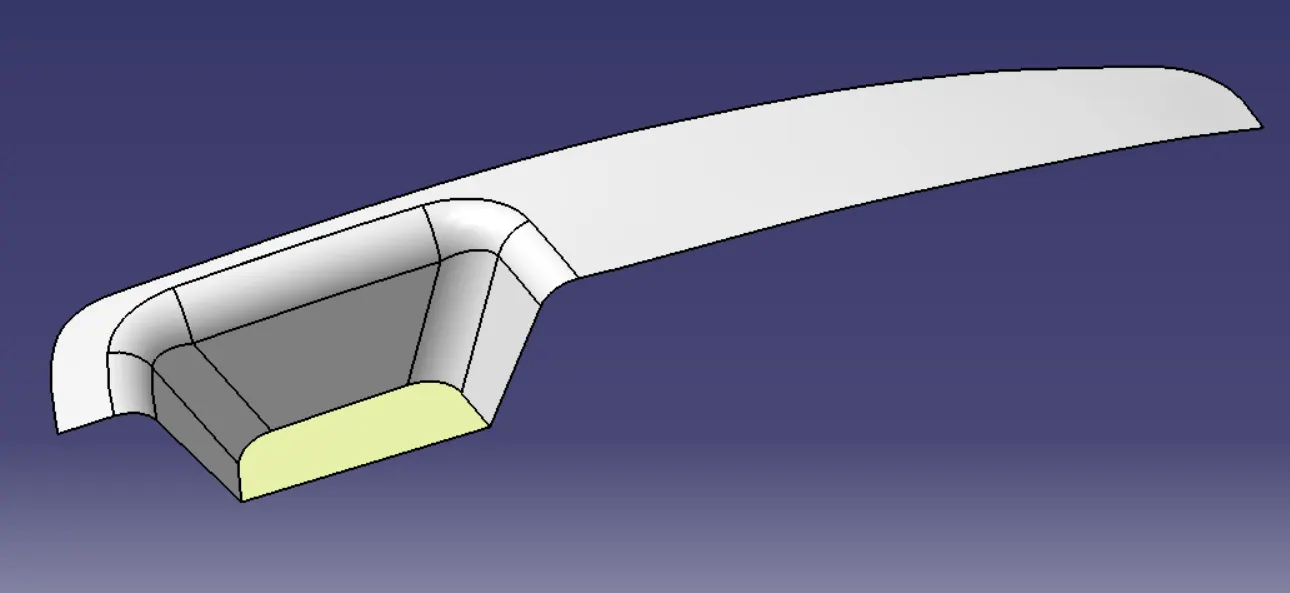
Extract the Base surface
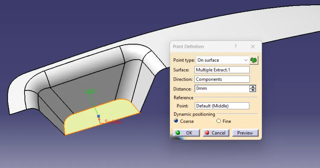
Point on surface origen
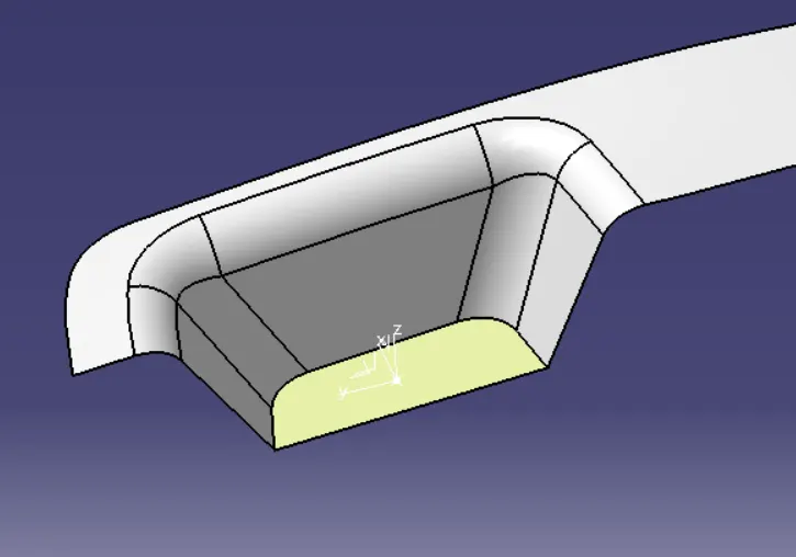
Insert the Axis System on the extracted surface
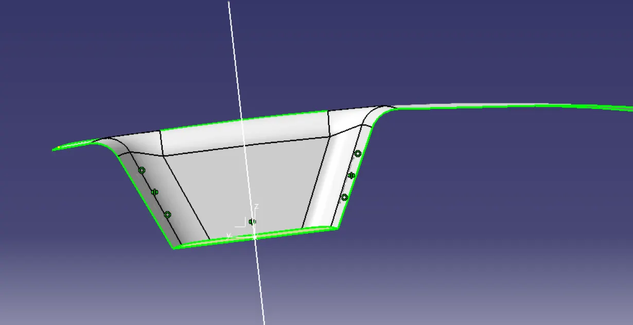
Tooling Axis in yz plane
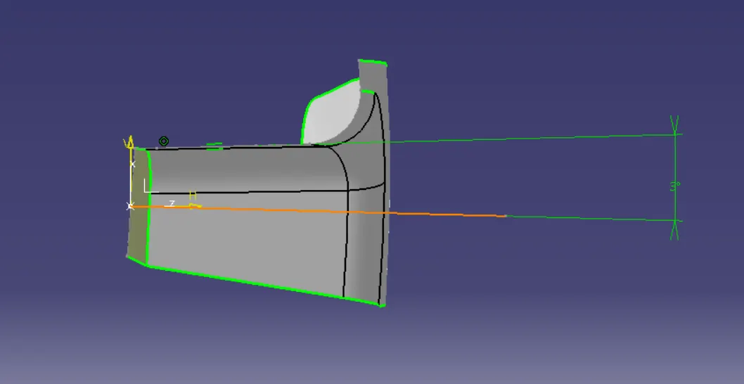
Tooling axis in xz plane
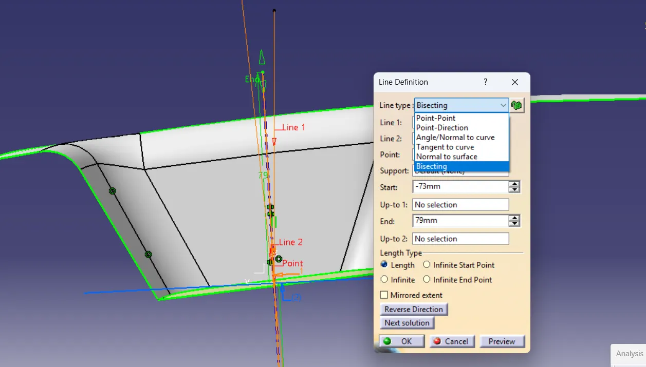
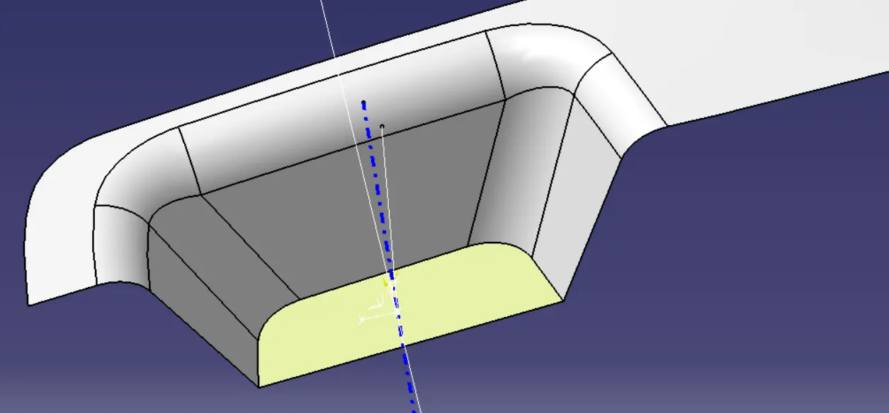
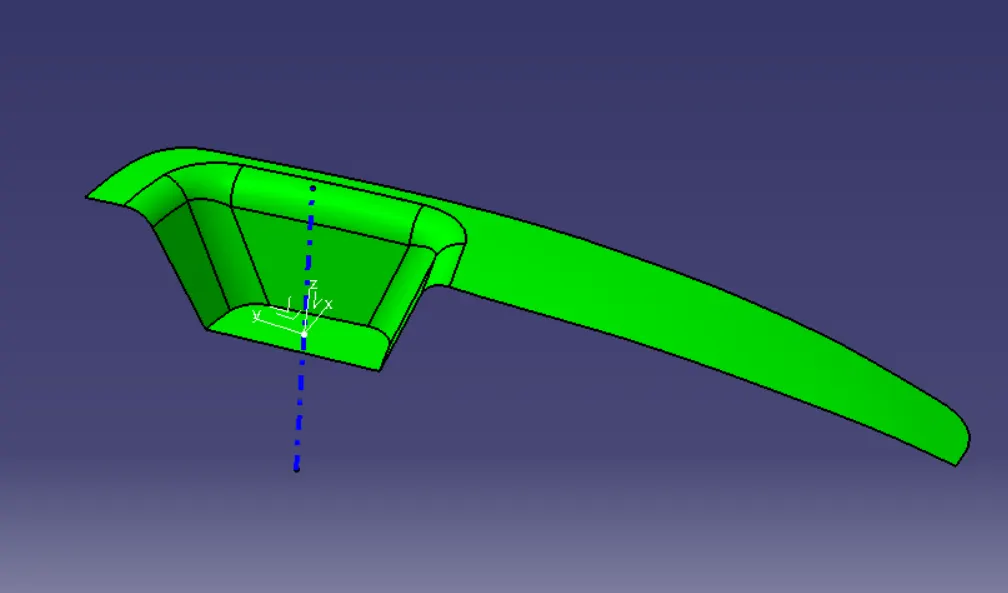
Final Tooling Axis Created by Bisecting method
Draft analysis of Class-A:
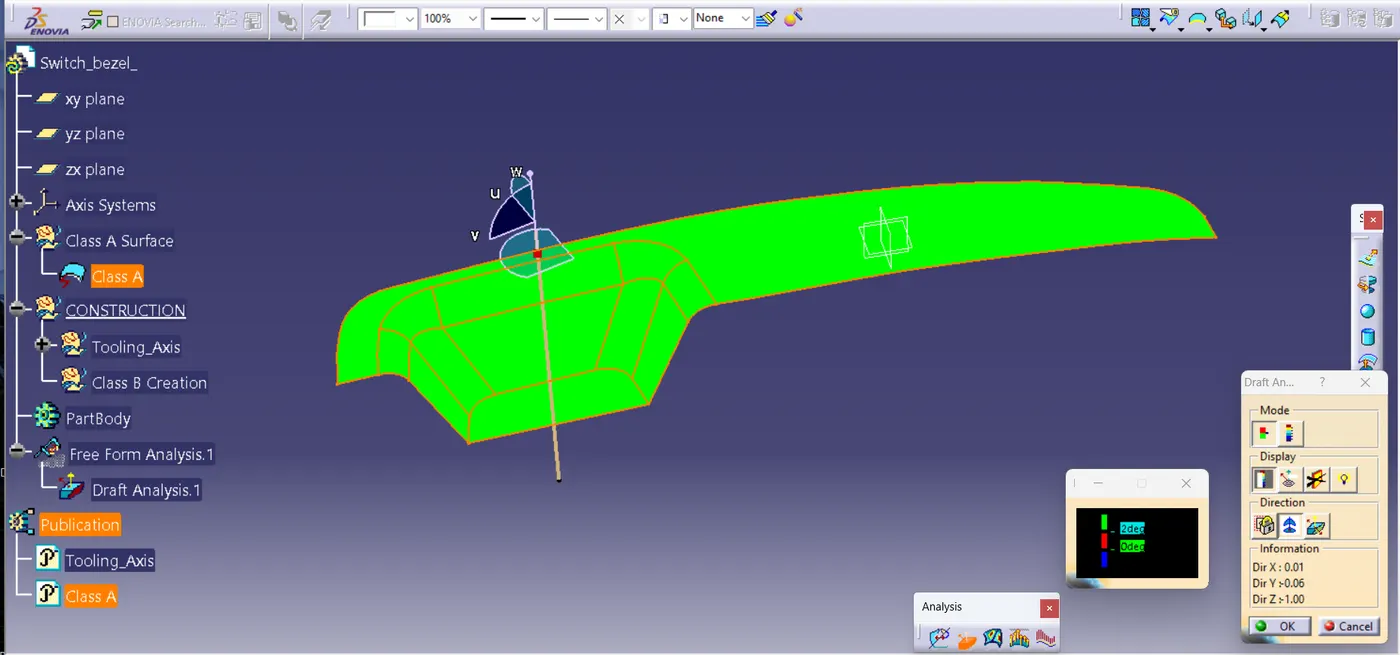
To continue with the design process, first we need to find out the tooling axis for the surface and check for all drafts using the Draft Analysis tool. Use the main tooling axis for the draft analysis using with 3° draft.
Class-B Surface:
The process of conversion includes a method where the input Class-A surface must be repaired by filling all the gaps. Then, offset the Class-A surface and use surface commands like sweep, extend, trim, etc. to create a Class-B surface and use the thickness option to create a solid part.
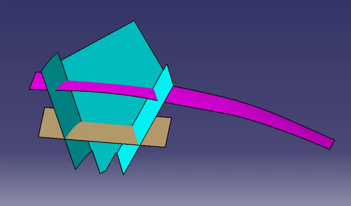
Creating Class B surface using Extraxt, Untrim, Extrapolation, and Offset referenced by Class A
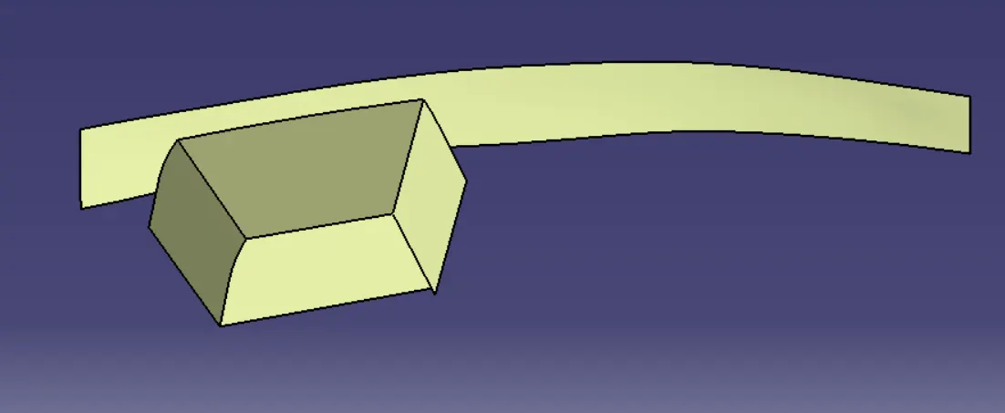
Class B surface trimmed to obtain outline geometry
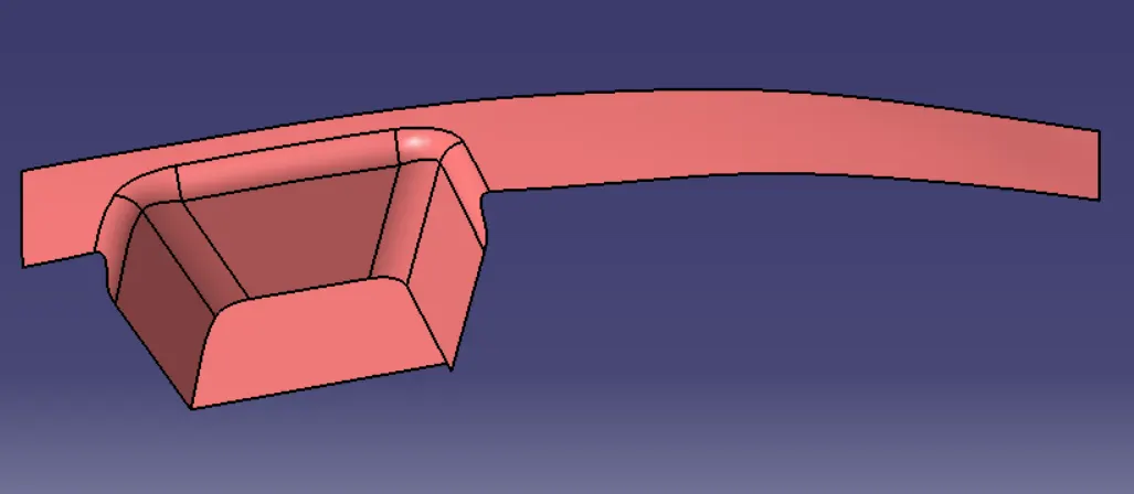
Fillet added to Class B surface
(Fillet radius = Fillet radius of Class A - Thickness)
Creation of Class C Surface:
In Class C surface is created by extracting the boundaries of the Class A surface and using the sweep command and the direction of draft. Surfaces are created, and these surfaces can be made smoother by using the smooth curve feature. Extrapolate and join the Class C surface to get a seamless Class C surface.
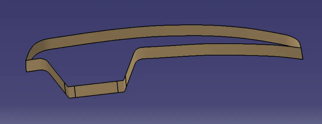
Join the Class A and C surfaces, if there is an open boundary remaining because of the curve smoothen. The Class A surface can be extrapolated by a tiny amount and trimmed with the Class C surface.
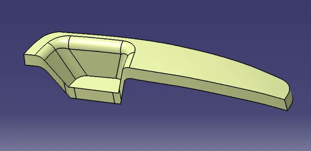
To check proper intersection or not using Boundary command
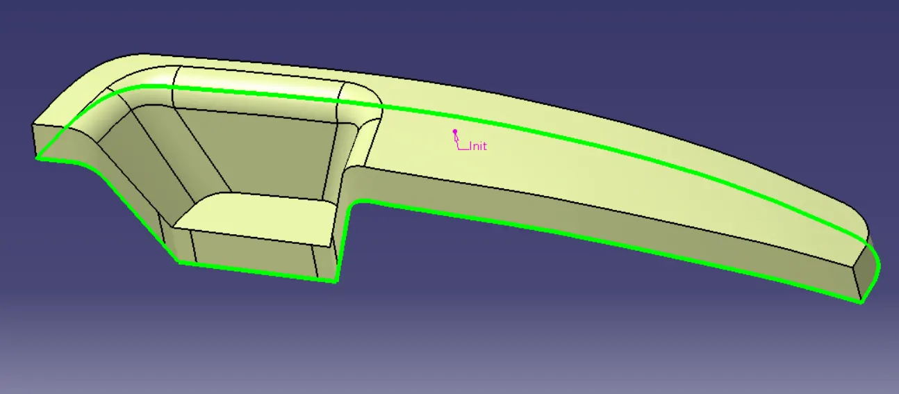
After getting a join & trim of Class A & C surfaces, trim the result with the Class B surface, and we get a close surface, and we make it part.
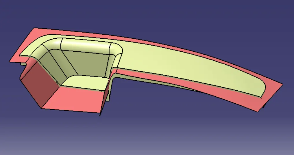
Similar to the previous, make sure that no open boundary remains so that part body can be formed using the final surface.
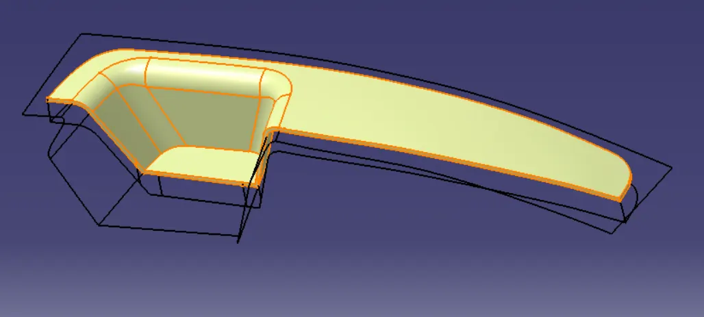
Creation of Part Body:
Using the close surface feature, make the part out of the created surface.
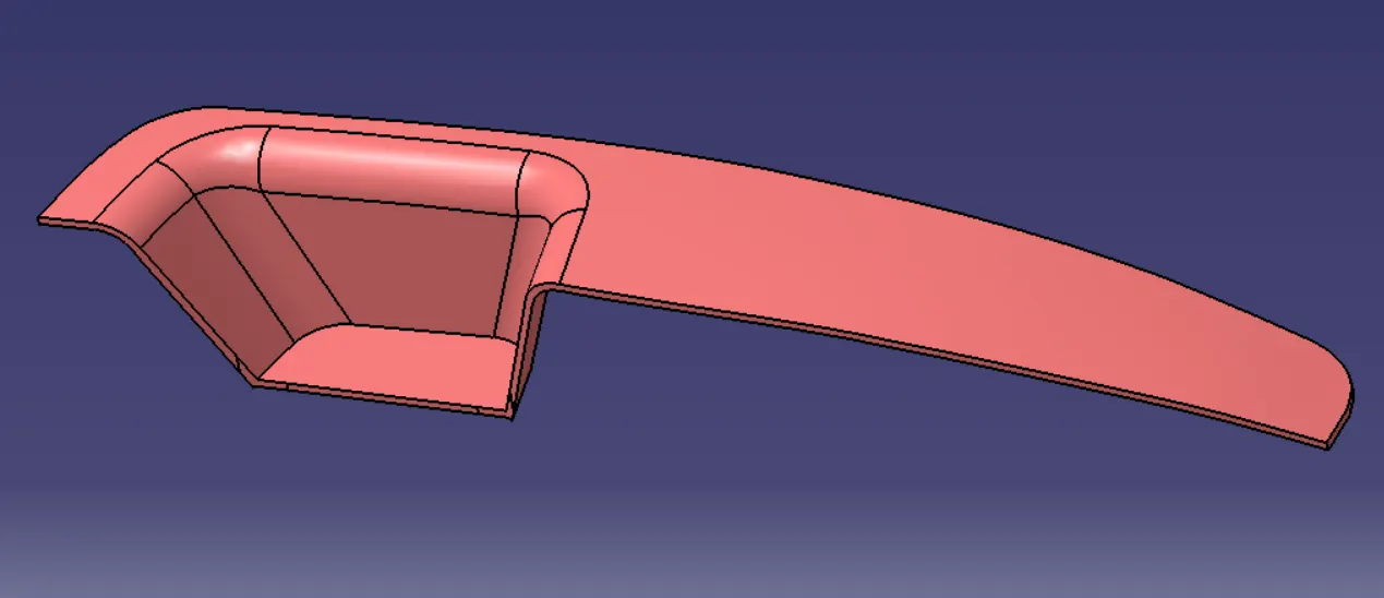
Part body created using close surface
Draft Analysis of a Part Body:
Using the tooling axis and a similar method to the previous, analyse the part for the draft angle in all surfaces. Make small changes in the angle of the draft and angle of pull until all surfaces are shown to have proper minimum values of draft.
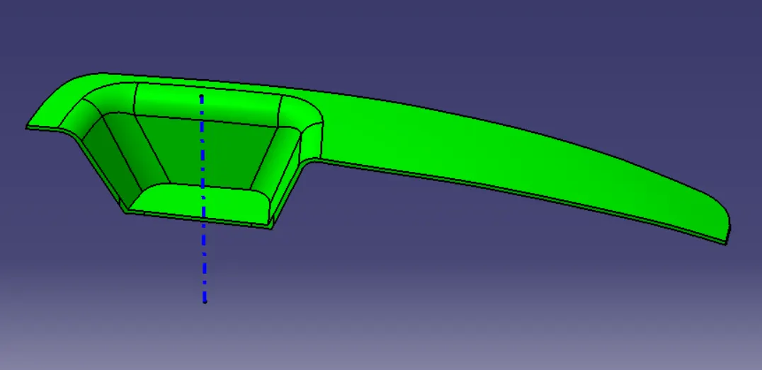
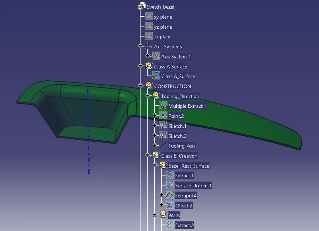
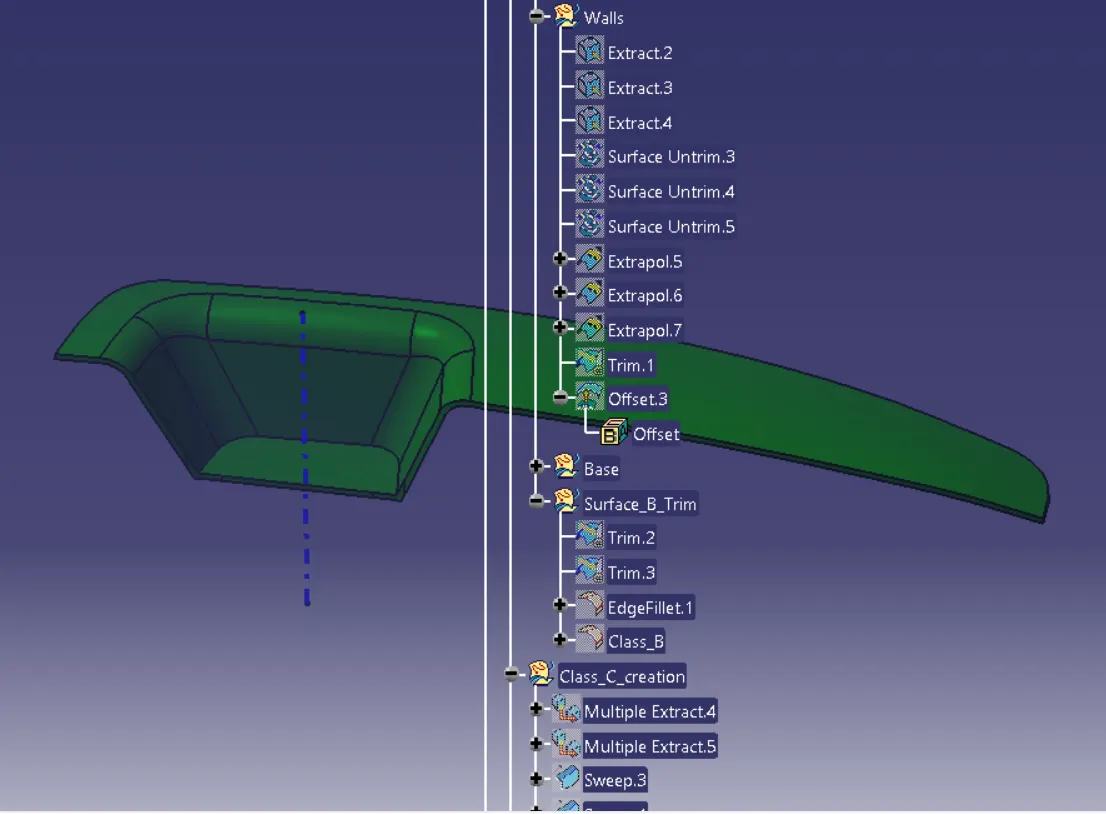
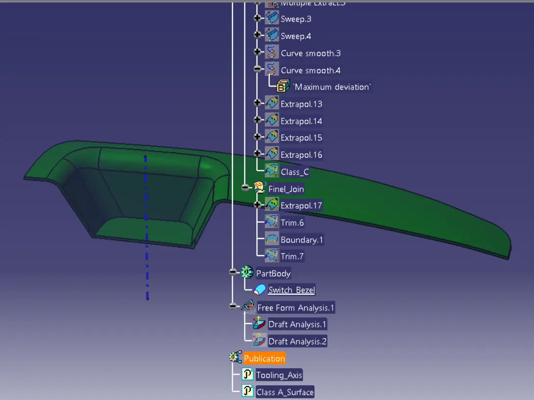
Tree structure:
SomeOrientations:
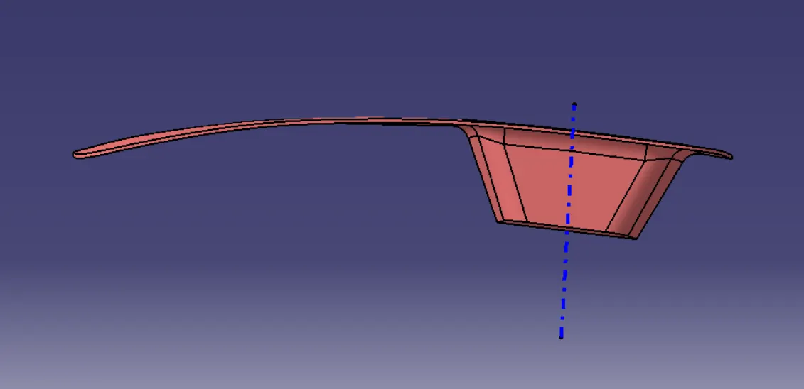
Front View:
Top View:
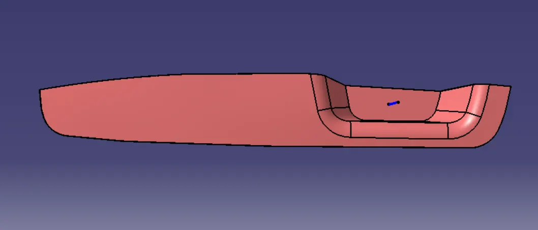
Isometric View:
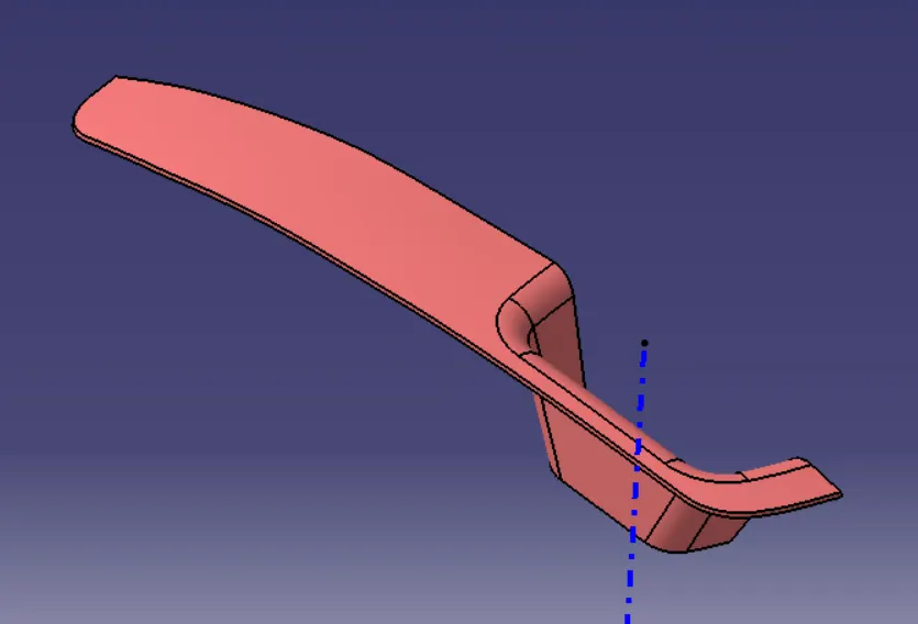
Conclusion:
Finally, the Class A, B, and C surfaces with the tooling axis have been published and the Switch bezel is moved on to the designing of the next operation.