Week 9 - Challenge 2 - Switch Bezel Design
PROCEDURE TO CREATING CLASS A SURFACE:-
- First, the given styling surface is checked for any irregularities and if found any then it is corrected by using Trim, Extrapolate, Split and Join commands.
- The Class A surface has some irregularities shown in below figure.So join operation performed on the surface and it became clean surface.
CREATION OF TOOLING AXIS:-
- Considering the Ejection from the cavity of the mould after manufacturing the interior trim (switch bezel) must have the nominal 3-degree draft angle.
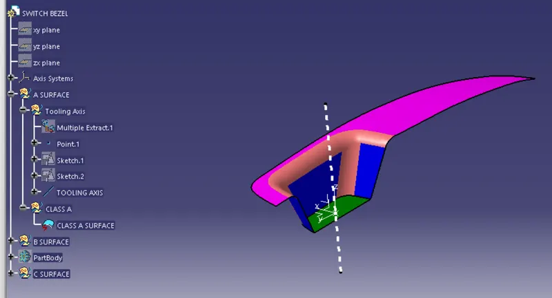
- Hence the tooling direction is created by considering the above factor and bisecting method is used.
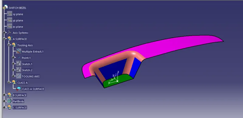
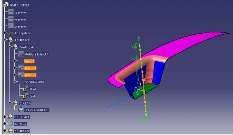
- The base surface of the class – A was extracted and a point at the centre is created and an axis system was inserted to the point with the current feature is disabled.
- Then, using project intersection along yz plane is created and the two inclined lines were drawn inside the positioned sketch.
- Then bisecting lines with the two inclined lines were drawn.
- Now the same procedure is done along the xz plane but on one side we don’t have inclined lines so the centre point is used to extrude a line along the z-direction and gave a measurement of 6 degrees (Tentatively).
- With these two lines from sketches 1 and 2, the bisecting line is crated and published as Tooling Axis(tooling direction).
CREATION OF CLASS B SURFACE:-
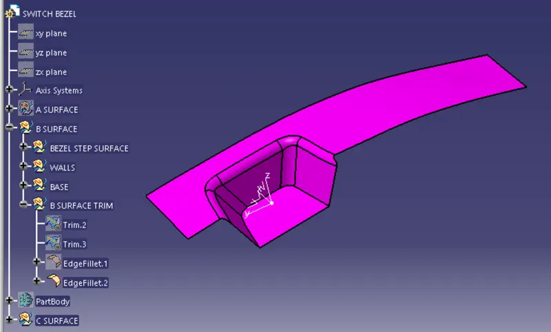
- For creating the class-B surface the required surface except the offset surface have been extracted and then untrimmed all the surface.
- Then all the surfaces have been extrapolated to get intersections between them.
- Since the thickness of the Switch bezel is 2.5mm the B-Surface was offset to 2.5 mm and the required trim operations must be carried out.
CREATION OF CLASS C SURFACE:-
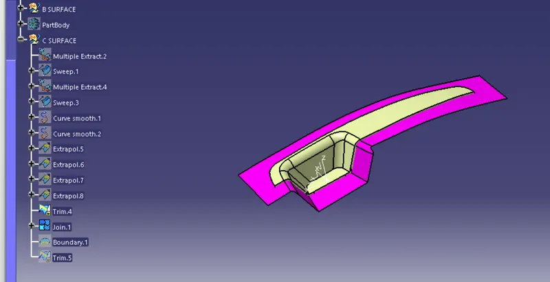
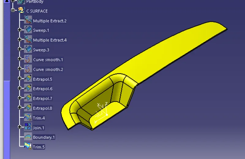
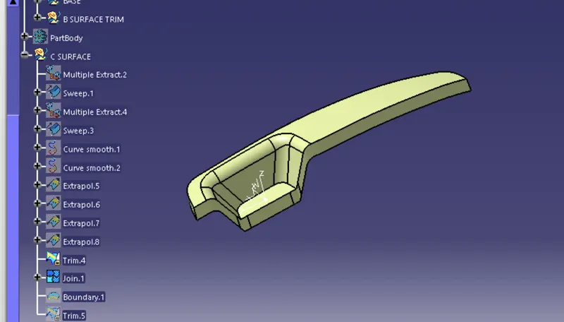
- The required outer edges of the A-Surface were extracted using Multiple Extract. Then for avoiding the patches the curve is smoothened using the Curve Smooth option.
- Then by using the sweep command the surface was created with the following feature controls,
- Profile type – Line
- Subtype – With Draft Direction
- Guide Curve – Smooth Curve
- Draft Direction – Tooling Axis
- Draft Computation Mode – Square
- Angle – 3 Degree
- Angle Sector – Positive Downward (1)
- Length – 20mm
- Then by using extrapolate command the edges were intersected between the surface corners which eases the trimming operation.
- Now the required portion of the C – surface were trimmed out.
CREATION OF CLOSED SURFACE:-
- Now the class – A and Class- C surfaces were joined together by removing the gaps in-between them with the help of extrapolation(tangent continuity) and Trim surface.
- Then the exact surface of the Switch bezel was trimmed from the above-resulted trim surface with the class-B surface.
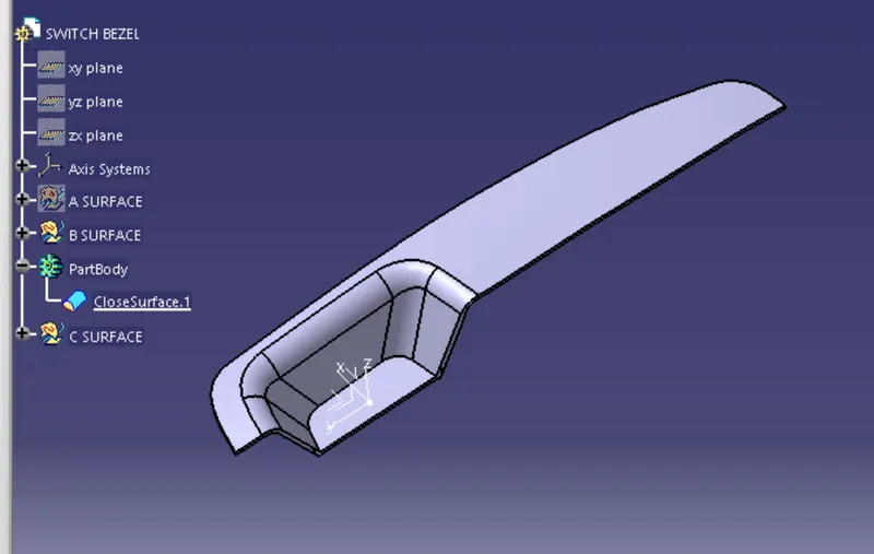
- Then, by defining the part body by using the Closed Surface command in Part Design, the component's solid body is created.