Week 9 - Challenge 2 - Switch Bezel Design
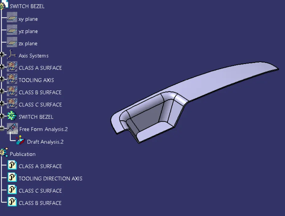
Aim:- Create the Switch Bezel Plastic component through the given Class-A surface. To begin with, the tooling axis for the given Class-A Surface should be created meeting the requirements of the draft angle and at the end perform the Draft analysis on the model.
Requirements:-
- Tooling Axis
- Draft Analysis
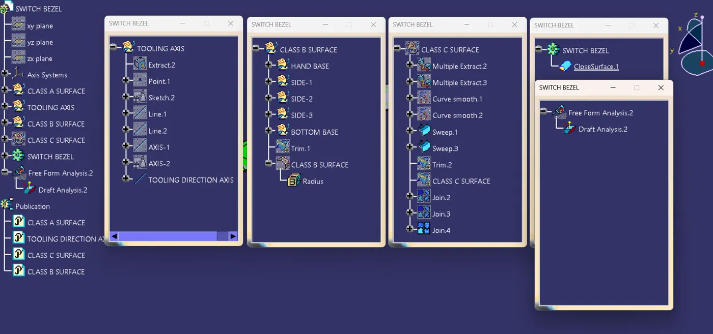
- Class B and Class C Surface
- Detailed Report
Tools used:- Following tools were used to reach the final step,
- Extract
- Un-trim
- Trim
- Extrapolate
- Offset
- Edge fillet
- Boundary
- Sweep
- Join
- Close (part design)
1. Tooling Axis:-
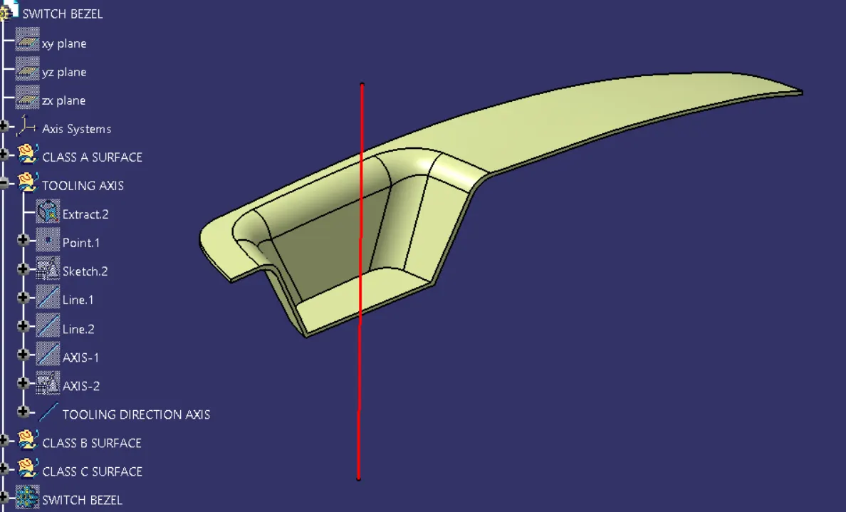
Its direction in which the mold or core and cavity opens is the tooling axis. Also its predefined the feasibility of componenet very easily. For tooling axis following points to be consider.
- First ensure the class-A surface is properly joined and has no discontinuity on it. For this we can use boundary command or join command.
- Analyze the model manually or visually to see which direction is most suitable for tooling axis.
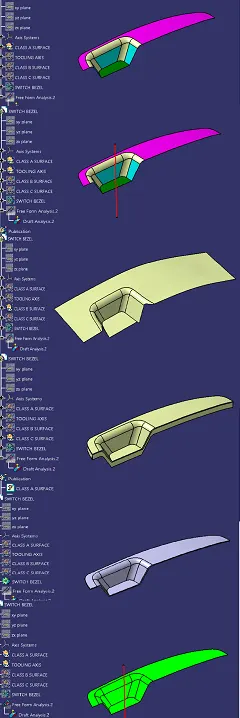
- As in 3D view we can see 2 holes and a flat surface, we can directly take the tooling axis perpendicular to that. But to be sure,let us analaze from all the views. The below images of the front side and top views shows the areas that we have to keep in mind while choosing tooling axis. As from X we cannot see one hole so we cannot take axis along this. In Y we cannot see any holes so here too we cannot take tooling axis. But in Z we can see 2 holes and flat surface so we can take tooling axis.
2. Draft Analysis:-
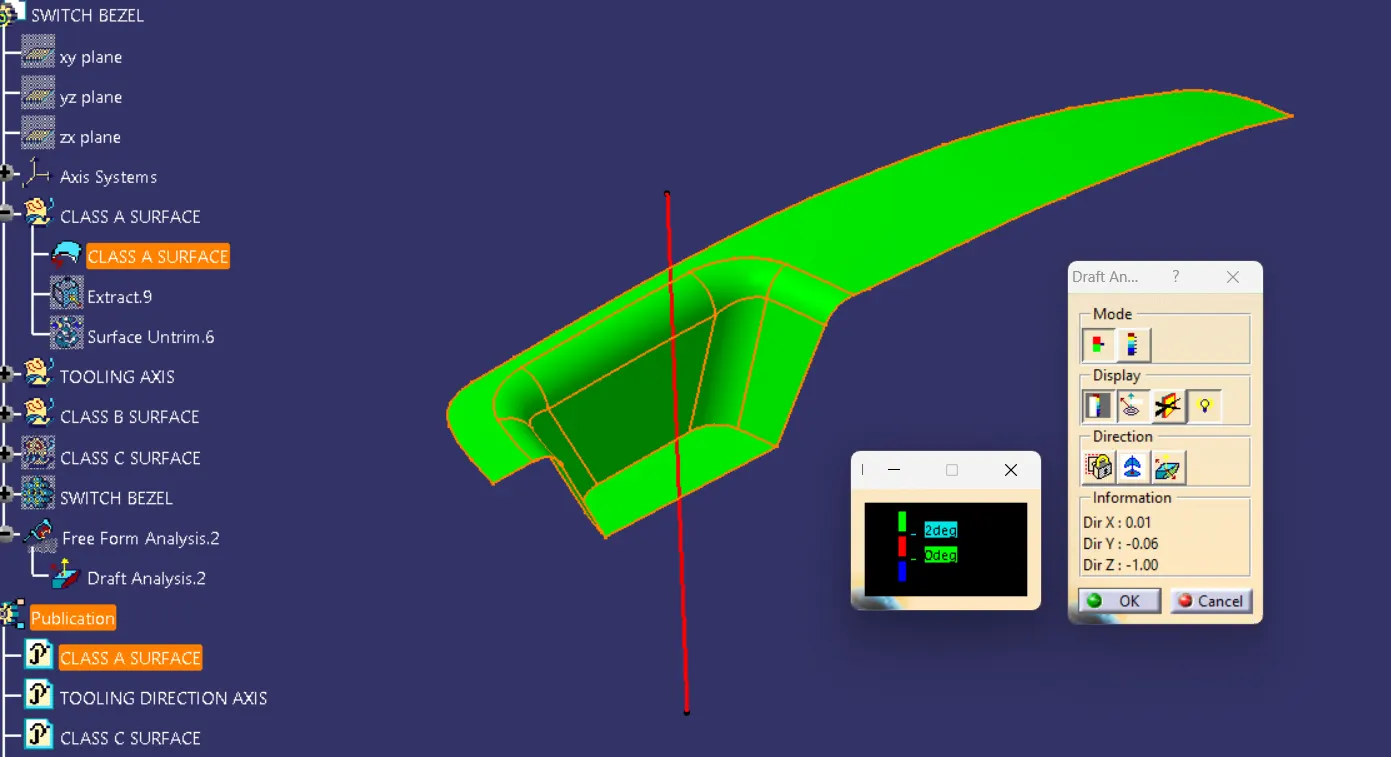
The Draft Analysis allows the user to easily analyze a part for proper draft angle. A Draft Angle describes the amount of taper for molded or cast parts perpendicular to the parting line. The given angle for draft analysis in plastics mold design is 3 deg, also its pre-define the feasibility for plastic models.
3. Class B and Class C Surface:-
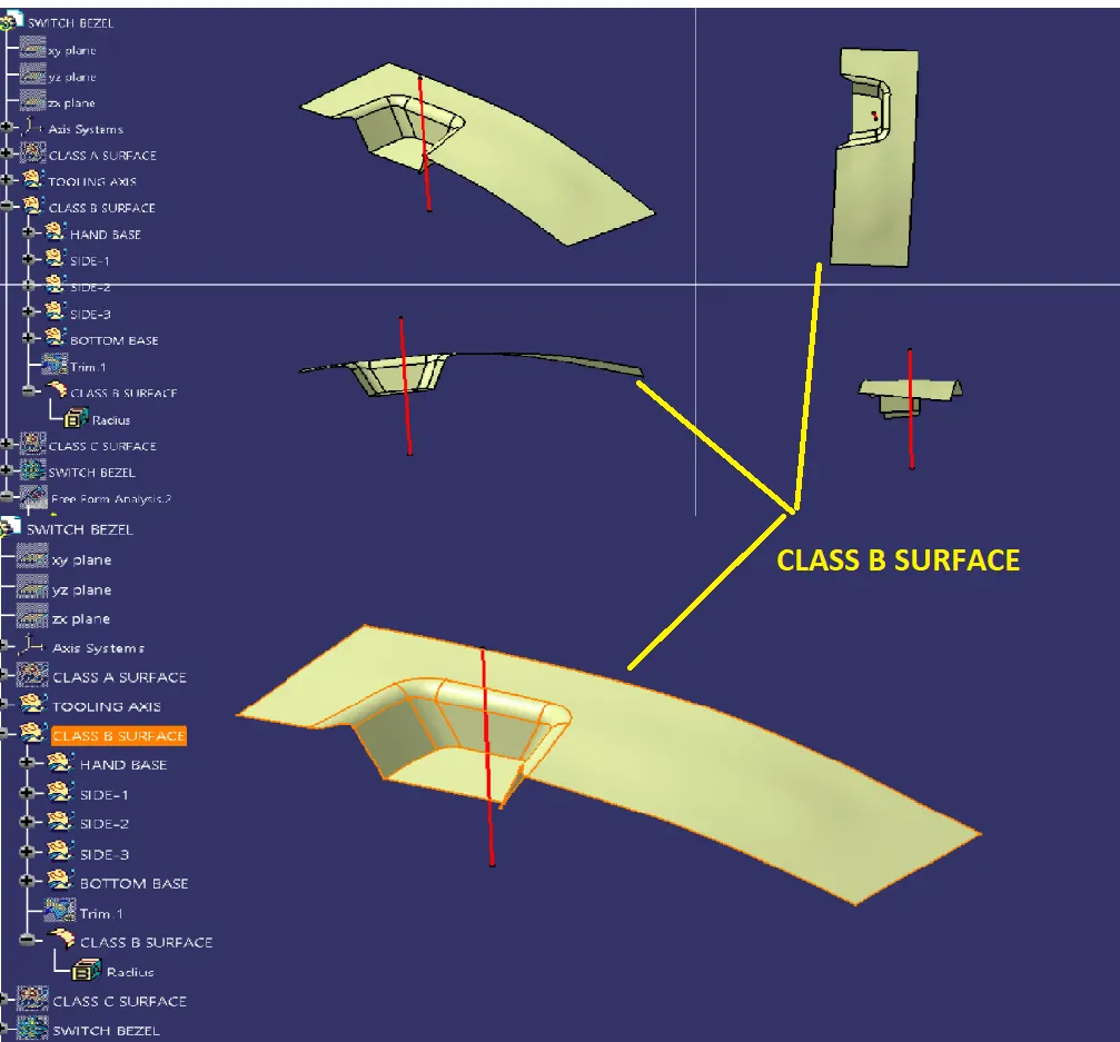
Class B surface
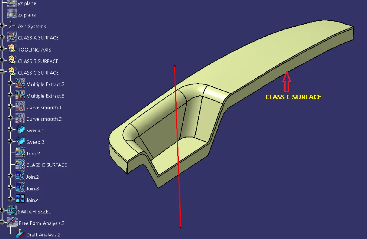
Class C Surface
Creation closed solid surface
Now the class – A and Class- C surfaces were joined together by removing the gaps in-between them with the help of extrapolation(tangent continuity) and Trim surface.Then the exact surface of the Switch bezel was trimmed from the above-resulted trim surface with the class-B surface.Then, by defining the part body by using the Closed Surface command in Part Design, the component's solid body is created.
Conclusion:- In this way we have successfully created tooling axis, class B & class C surface, draft analysis, solid body from class B & class C surfaces of Switch Bezel Design.