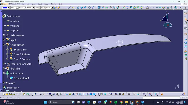
Week 9 - Challenge 2 - Switch Bezel Design
Report -
In this challenge i have created a component named as switch bezel. With the help of given class a surface.
steps -
1. Create tooling axis - First i have create a Tooling axis. For a molding operation first we need tooling direction for core and cavity movement with minumum draft angle. This axis helps to do that.
To create tooling axis first i have generate a point in center of base of the swith bezel. than go to sketch workbench choosing positioned sketch workbench in point 1 and select yz plane in a axis system located at point 1. With th help of side walls create two lines parallel to tham by intersect 3d element. Than create a line that bisect those two lines through point 1 . Keep this bisecting line and generate one more line that is at an certain angle with third wall and passing through point 1.
And at the end create a line that will this two lines through point 1 this one is a tooling axis for switch bezel.
2. Creation of B surface - To create a b surface first i have extarct all the surface that i want (bezel rest, walls and base) ,than untrim that surface , than extrapolate (side walls and base) surface by selecting sides and point continuity. Than one by one selecting all the surfaces and offset by 2.5 mm , because i have to Take the Thickness of the component to be 2.5 mm.
Do a fiilet operation as required by check the dimenssions.
Than respectively trim all the surface ,the result is a b surface. Save it as a class b surface geometrical set.
3. Creation of C Surface - create a geometrical set name it as class c surface. To create a c surface we can create a boundary or either we can give a multiple extract definition to the boundary of th class a surface. To do a sweep operation. As a result there is a two surfaces in c surface extrapolet both sides of both surface than trin that surfaces result is a final C surace.
4. Final trim - Before final trim check for boundary if there are any extra boundary that i don't want so i have to first remove that boundary. To remove that boundary first i have do join operation than curve smooth. After that there is a two more extra boundary to remove this two surface i have extrapolate class a surface by 0.05 mm. Result is don't have any extra boundary.
trim class a surface and class c surface with result do a final trim with class b surface. With final trim do a smoth curve operation.
5 Publications - publish tooling axis and class a surfase.
6. check boundary - After final check for boundary if ther are any boundary it means need to do corrections, if it shows error means product correct.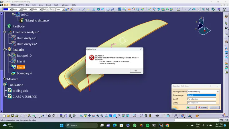
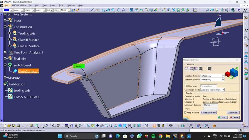
7. Check thickness - By measuring dimensions distanse between class a surface and class b surface there is all over it shows 2.5 mm.
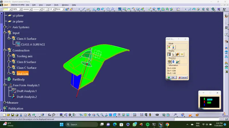
8. Draft analysis - Do a draft analysis by positioned the compas normal to the tooling axis. sets the angles negatives shows in a blue colour , between 0 to 2.8 degree it shows in a red and above 2.8 degree it shows in green. I Have checked for draft analysis and i think it is ok.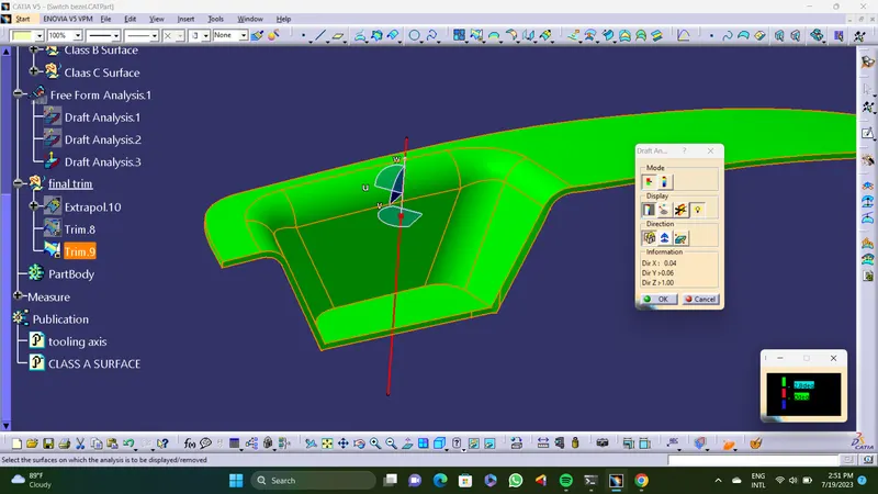
9. Close surface - And at the end by doing a close surface operation. This one is a final product switch bezel.