Week 9 - Challenge 2 - Switch Bezel Design
Aim :
Create the Switch Bezel Plastic component through the given Class-A surface. To begin with, the tooling axis for the given Class-A Surface should be created meeting the requirements of the draft angle and at the end perform the Draft analysis on the model.
Take the Thickness of the component to be 2.5 mm.
What is Draft Analysis ?
When a plastic component is made, we can observe that there is a draft angle given on each side from the base which is lesser than 90 degrees. This is because in the criteria of making a plastic material the mold should release the material when finished. if the mold surfaces are 90 degrees the material won't release from the mold because of friction due to contraction of material when cooled.
To resolve this problem we CAD engineers maintain a standard rule to design the plastic mold or die's in such a way that there is no problem while ejecting the plastic component. So a minimum of 3 - 10 degrees of draft angle is given to every plastic component while designing.
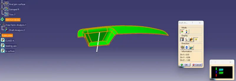
Draft analysis is performed on the given Class-A surface, and it is clearly observable that there is no negative draft on the surface.
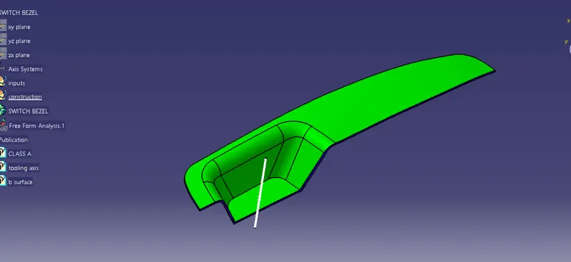
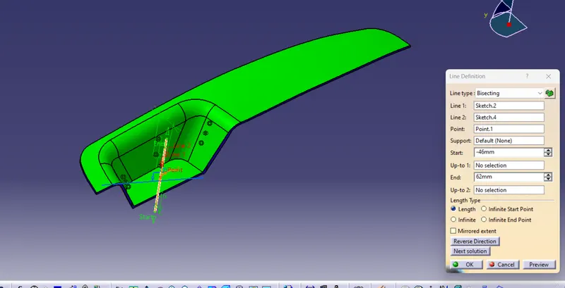
Creation of tooling Axis (Bisecting method)
1. Extract the base surface of the given Class- A Surface and create the center point of the Extracted surface.
2. Then create two sketches on two planes by taking the cross section of the given surface in the particular plane.
3. Tooling axis created from the two lines using the cross section of the surface on y plane as bisecting line.
4. Tooling axis created from the two lines using the cross section and also creating one with the help of cross section line of the surface on X plane as bisecting line.
5. Now by creating another bisecting line using those two plane sketches is the tooling axis for this particular Class - A surface.
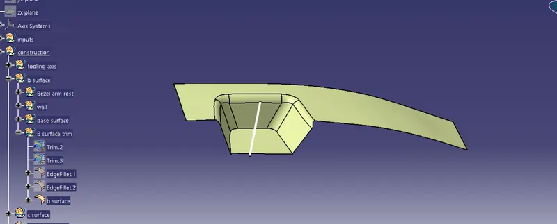
Creation of Class - B and Class - C surface
Extracting the class - A surface without the fillets and then untriming and extrapolateing them to join them, and after that offset the surface to 2.5 mm thickness which forms as the Class - B surface.
class B surface:
Class - C surface
By extracting the boundary of the class - A surface, the surface required for the class - C is obtained.
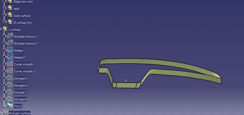
using the smooth curve option a smooth surface can be obtained by sweeping the line towards the direction of the tooling axis.
Final out put :
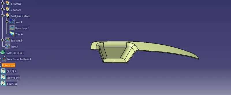
Triming and joining the all the class surfaces together.
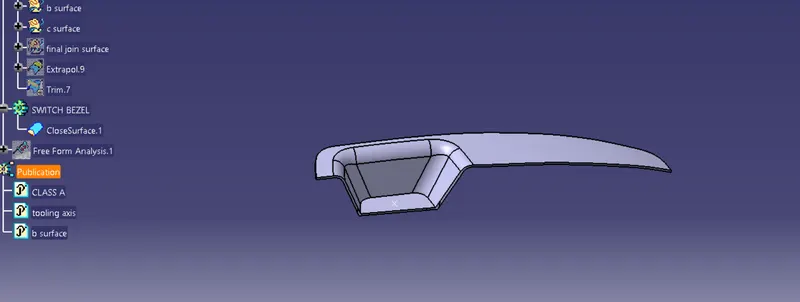
using the close surface tool on the final surface :
performing draft analysis on the final plastic solid model :
Conclusion :
Given Task is completed and Detailed report for the Draft Analysis of Switch Bezal is presented above .