Week 9 - Challenge 2 - Switch Bezel Design
ANSWER:
BASE BRACKET DESIGN
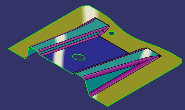
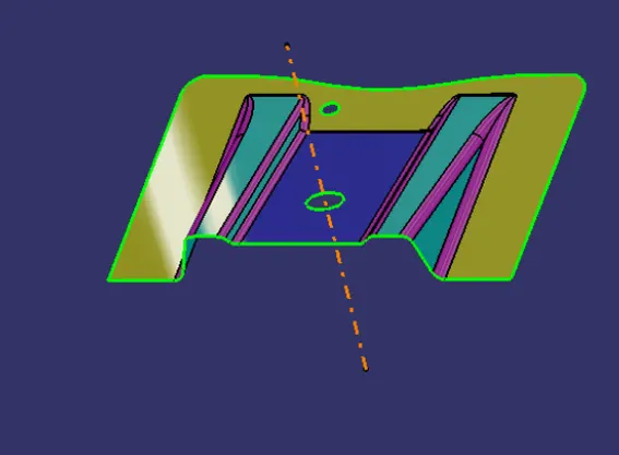
AIM: To create the Base Bracket Plastic component through the given Class-A surface by creating a tooling axis meeting the requirements of the draft angle and to perform the Draft Analysis on the solid model at the end.
GIVEN CLASS A SURFACE:
TOOLING AXIS:
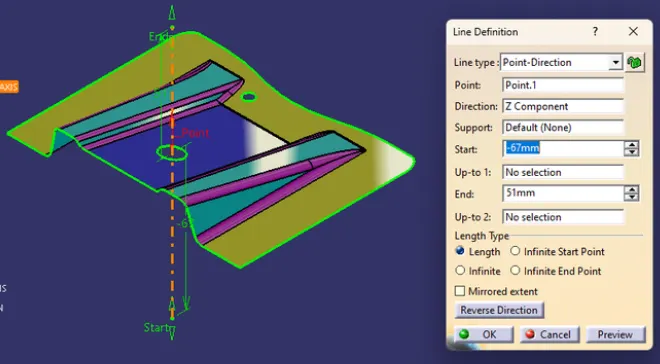
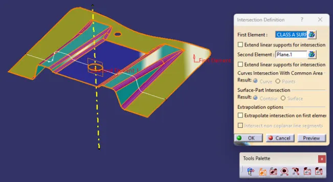
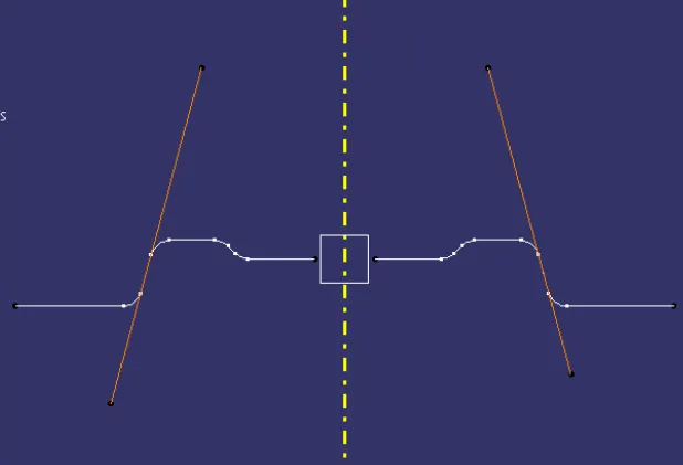
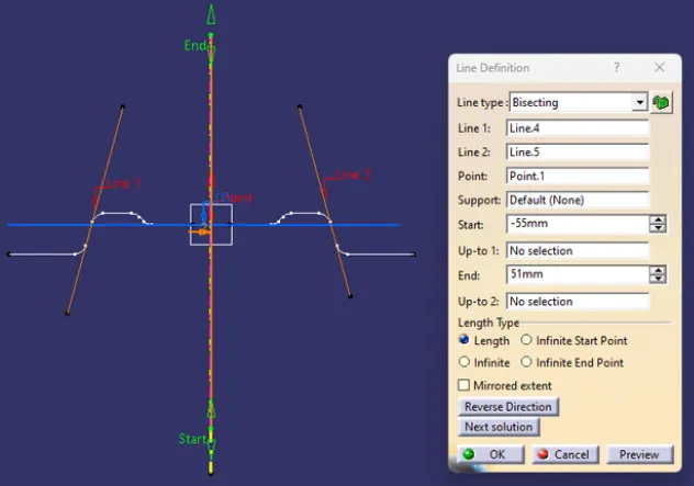
Tooling axis or Molding axis is the direction in which the core and cavity opens. It is basically the direction that the mold pulls apart. Creating a tooling axis is necessary to provide draft angle and analyze them. The tooling axis is created using Bisecting method.
BISECTING METHOD:
To decide the Tooling axis, it is made sure that the component is clearing the tooling axis in the given specific direction. The first step is to visually check the component for the best tooling direction in all three x, y and z directions. In the given Class A surface it is found that the best tooling direction is Z axis as the holes present on the surface cannot be cleared in either X or Y directions with minimum tooling. So Z direction is chosen for Tooling axis.
After the selection of direction, a dummy tooling axis is created in that direction for reference.
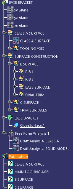
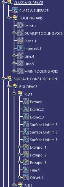
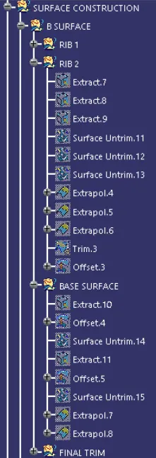
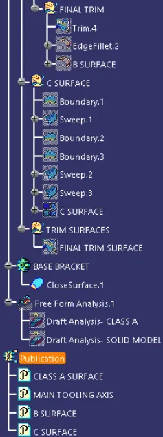
EXPANDED TREE STRUCTURE:
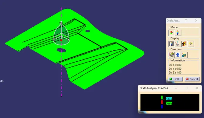
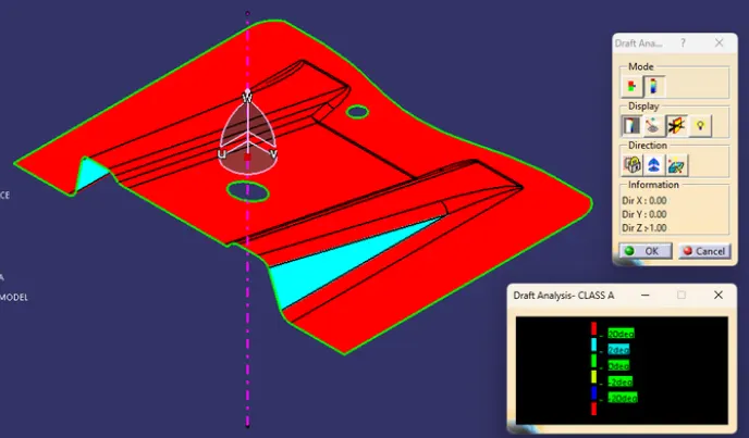
DRAFT ANALYSIS ON CLASS-A SURFACE:
FINAL SOLID MODEL:
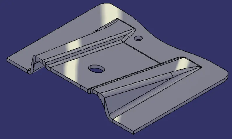
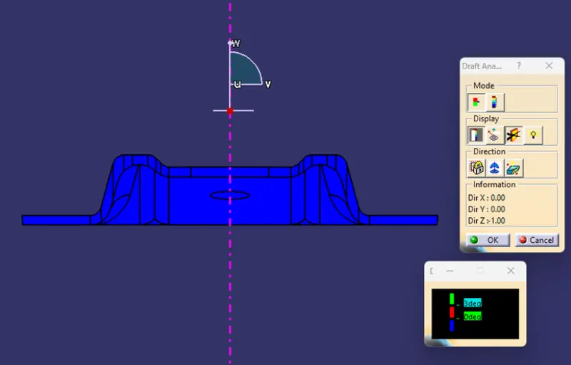
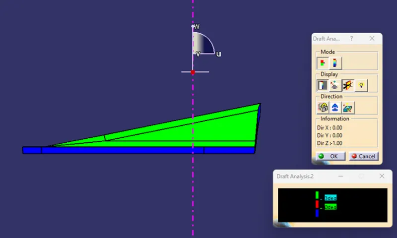
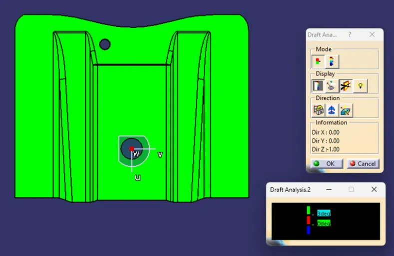
DRAFT ANALYSIS ON SOLID MODEL:
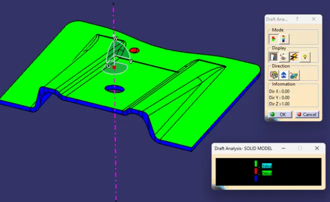
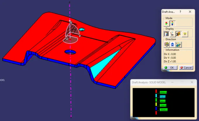
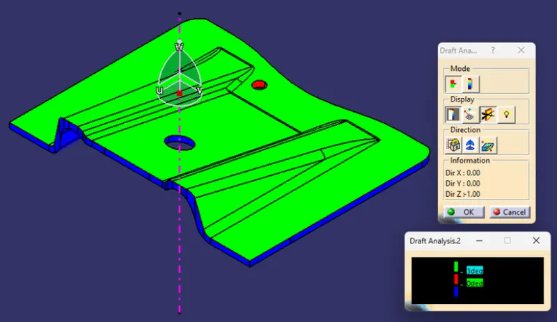
DRAFT ANALYSIS ON SOLID MODEL IN VARIOUS ORIENTATIONS:
ISOMETRIC VIEW:
FRONT VIEW:
SIDE VIEW:
TOP VIEW:
CONCLUSION:
The Design of Plastic Component - Base Bracket from Class A is completed using concepts of Draft angle, Draft Analysis, Tooling Axis, Class B and Class C creation and converting Closed surface to a solid part