Week 9 - Challenge 2 - Switch Bezel Design
AIM
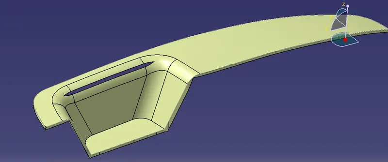
Create the Switch Bezel Plastic component through the given CLASS A surface.To begin with, the tooling axis for the given class A surface should be created meeting the requirements of the draft angle and end perform the Draft analysis on the model.
WORKBENCHES USED
- Wireframe and Surface Design
- Part Design
PROCEDURE
- Creating Tooling Axis
Consider the base surface between the two slanting faces. Define a point,Axis and a position sketch with YZ reference. Then use Intersect command and click center graph then we get an intersection yellow line. Draw two line on the two slanting line. Use Bisecting Line command to get a common line between the two line then, convert the two slating line to contruction lines through the sketch solving status geometry.
Consider the base surface and then define position sketch with ZX plane reference.Use Cut Section command and then use Intersect command as used before to get the intersecting line and then draw a line close to the horizontal line and then draw another line so as the distance between them should be 3 degree. Go for the sketch solving status operation as before.
So, we got 2 line from two sketch so define a bisecting line with the two lines as reference. So we gets a Tolling Axis. Check it in the normal view as to get every faces of the surface shall be visible.
- Creation of B Surface
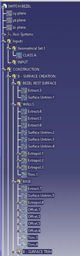
Define a geometrical set named B - SURAFCE CREATION. THen under it define a set named BEZEL REST SURFACE. Under it extract the top surface and untrim. Then Define a set named WALLS under the b surface and then extract the surrounding walls of the bezel and then untrim them. Extrapolate the walls for getting the intesection between them. Define a sset named BASE under the b surface and do extraction , surface untrim and extrapolate to it also as before.
Do Offsetting on the walls, Bezel and base. Considerring the distance as 3mm. After the offsetted surafces creation do trimming to get the B Surface. Add proper fillits to it also(Edge Fillet).
- Creation of C Surface
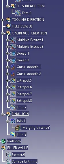
Define a geometrical set under the CONSTRUCTION like as the B- SURFACE CREATION which is C - SURFACE CREATION. Define Multiple Extract command around the edge of the bezel choose tangent continuity. Do the same for the lower edge of the bezel. Do sweep along the two extract and we get a surface. Do Curve Smooth command so as to get a proper surface of teh extracts and replace the multiple extracts with these smooth curves. Extrapolate the two edges at the either sides of the curves as to intesect them. Trim the surfaces together.
- Creation of Final Join
Define a new geometrical set FINAL JOIN under CONTRUCTION. Join the Class A surface to the Class C surface. Trim the Join wit the Class B surface to get the Required product surface.
- Part Body Design
Move to the part body design workbench and define the surface as a Close Surface body.
- Draft Analysis
Operate the draft angle mode.Go to the material mode and check customize view parmeters and activate material mode on it. Click on the compass mode in diraction tool. Keep the compass on the tooling axis firm alligned. Click lock mode on the direction tool and then click on red line on the body to get a green coloured orientation. Green means draft more than 2 degree and blue less than 0 degree.
So change blue colour to red and red to light blue and change 2 degree to 3 degree.
RESULT
The Bezel model was made and Draft Analysis was also carried out.