Week 9 - Challenge 2 - Switch Bezel Design
INPUT
CLASS A SURFACE
SWITCH BEZEL
ANS :
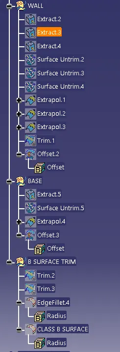
GEOMETRICAL SETS:
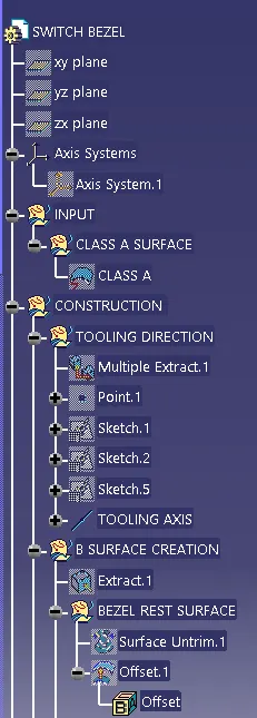
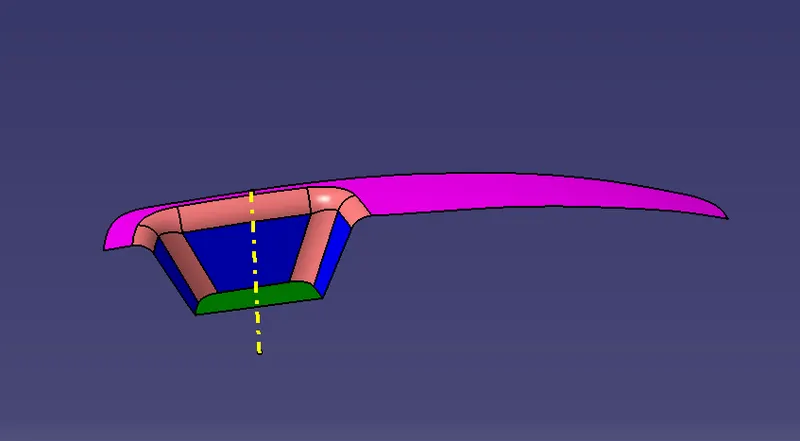
TOOLING AXIS CREATION.
First extract the base surface and create a point on it. after point creation insert the axis systen on that point.Then create two lines on two side surfaces and bisect them. After create two lines on yz axis one is intersecting and other will be at 3 deg and bisect them togather. Then create the bisecting line bu using this two bisecting line. Then we will get the tooling axis.
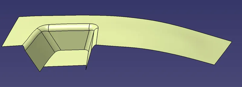
CLASS B SURFACE CREATION:
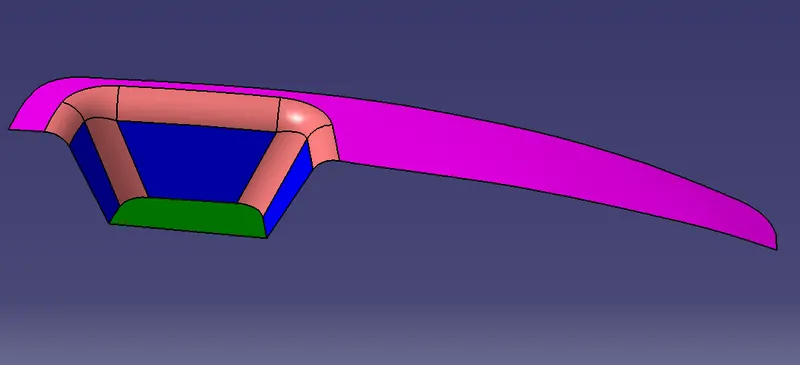
First extract the surfaces and then offset all surfaces with 2.5 mm on same direction.After that untrim all surfaces then extapolate all surfaces and trim it with each other. Then add the fillet with required radius.
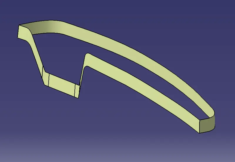
CLASS C SURFACE CREATION:
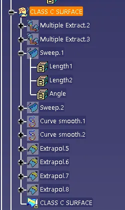
First extract the boundary of the class a surface by using extact or boundary option. Then swept it by using draft direction option & take maximum 3 deg draft angle with outside draft direction.
Draft analysis :
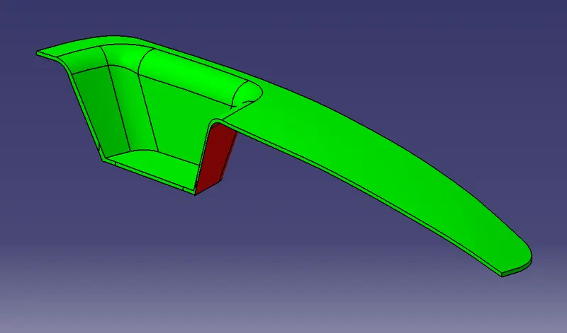
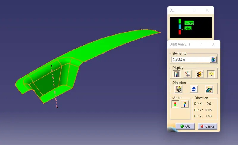
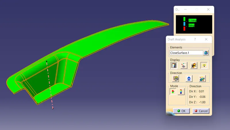
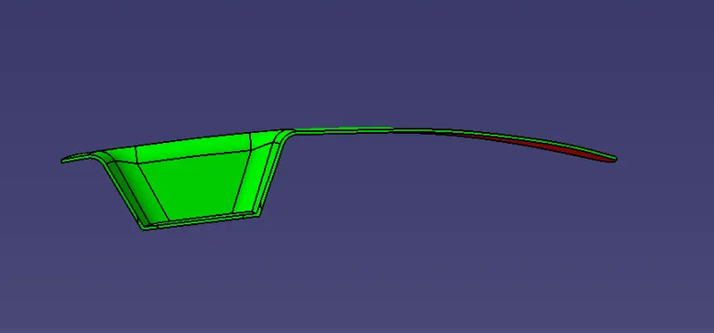
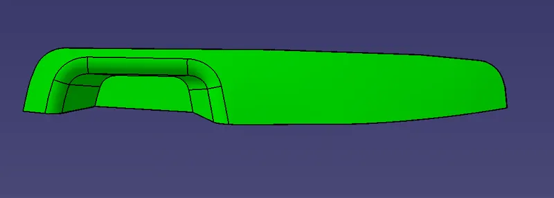
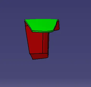
First the class-A – Surface is checked before creating the Class –B&C surface and finally the solid body must be analyzed. Both can be done by following the below procedures.By changing the view mode to custom view parameters – Material mode then the feature draft analysis is enabled.Then the compass was activated and placed with the tooling axis by dragging the red pointer and then locking it.Then, by selecting the quick analysis mode, the nominal value will be 3 degrees and checked for the component's draft angle.The green color area shows that it satisfies the 3-degree draft angle. If not satisfied then by using the Running point tool the area is measured and then altered to get a successful draft for the created tooling direction.
Draft analysis of class A surface :
Draft analysis of final product :
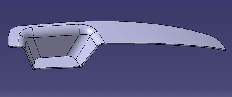
Final Product :
Solid model with the proper color code of the draft angle in various orientations :
FRONT VIEW:
TOP VIEW:
SIDE VIEW:
ISOMETRIC VIEW :