Creating the Connectors between the components
AIM :
To Create a connector between the various components in the given model.
OBJECTIVES :
1) To discritization of component with 2d shell Quad elements.
2) To Create a connector between Right Rail 2 & Front truss 1 by using an Semi-Quad(angled + capped + L) elements
3) To Create a connector between Left rail 2 & Front truss 1 by using an Quad elements
4) To Create a connector between Front truss 2, Front truss 1 & Right Rail 1 by using Spot weld with 3 layers and 5mm Diameter.
5) To Create a connector between Front truss 2, Front truss 1 & Left Rail 1 by using Hexa Adhesive.
6) To Create a connector between Rear truss 2 & Right Rail 2 by using Bolt Connector.
7) To Create a connector between Rear truss 2 & Left Rail 2 by using Bolt Connector.
8) To Create a connector between Right rail 1 & Right rail 2 by using Spot weld with Rigid elements.
9) To Create a connector between Left rail 1 & Left Rail 2 by using Spot weld with spring elements.
10) To Create a connectors between rest of the all components by using suitable elements.
CAD MODEL :
1) Open up the Hyperworks software and set the user profile which is 'Optistruct'. Click the "Import Solver Deck" option from where tool bar section, then click the "Import Model" option and select the appropriate file which we are gonna perform.
2) After click the import option, a model will shown up from the graphical window, by default "Geometry Color Mode" had selected at "Auto". We have to manually change into "By Topo" Mode for viewing the Topology edges like Free, sharped, supressed and Non manifold.
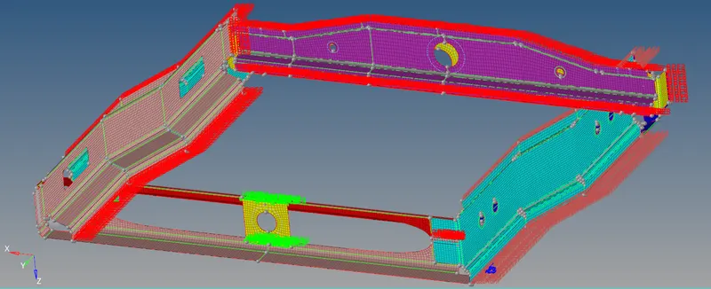
3) After Changed into 'By topo' mode, a model has looks like below image.
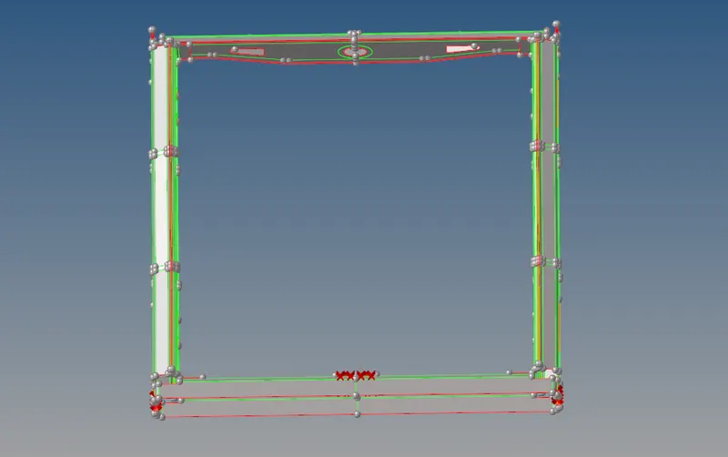
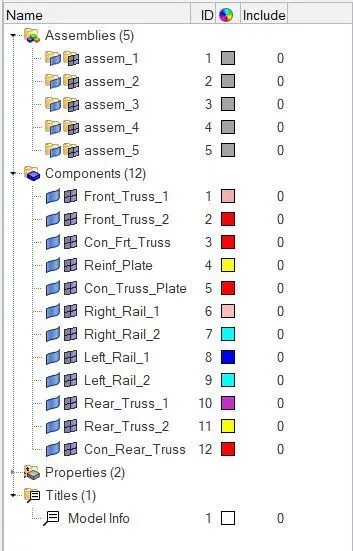
4) A Model contains 12 components, we have delete unwanted components from the model. In this case, we have to remove the points which are presented in the model.
5) We have delete the assembling without deleting the child components. A assembles are helps to customize the components as per our convenient. In this case, these kind of assemblies are not required.
6) We have to manually remove the 'Con_Frt_Truss, Con_Truss_Plate and Con_Rear_Truss' components.
PROCEDURE TO ACQUIRING THE OBJECTIVES :
1) Discritize the Components :
1) Go to the "Auto mesh" panel under "2D" Main menu panel, set the 5mm element size and element type is Quad. Select the surface, perform meshing operation on it.
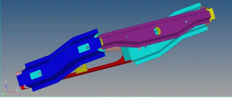
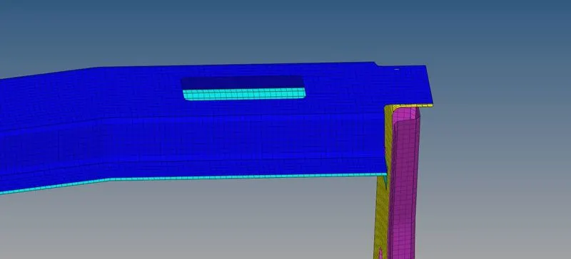
2) Here the meshing image which are created on the each components.
2) Creating a connector between Right Rail 2 & Front truss 1 :
1) We have to create a connector between right rail 2 & Front truss 1 by using "Seam-Quad(angled+capped+L) element.
2) Go to "Connector" panel under which "1D" main menu panel, the connector panel is available in all 1D, 2D & 3D as well. Click the connector option, select the seam connector and then select the element type which is "Seam-Quad(angled+capped+L)" and change the location into "Node Path" instead of "Line List".
3) Select the nodes at edge of the "Front Truss 1" component, then choose the components which are "Right Rail 2 & Front truss 1" and remaining options are set as it is default.
4) A spacing distance between connector elements is 4mm along the longitudinal direction. A actual distance between the two components is 3mm, so we put the tolarence value is 4mm for connector should be realise.
5) Click to "Create" option, a respective connector has been generated between corresponding components.
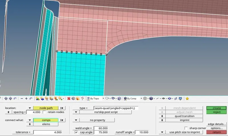
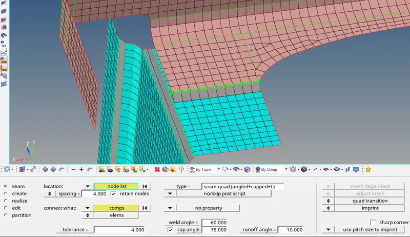
6) After creating the elements between them, a meshed elements are destoryed little bit. We have to perform for getting proper mesh.
7) After completion of all operation, a connector elements will look like below image.
3) Creating a connector between Left rail 2 & Front truss 1 :
1) We have to create a connector between Left rail 2 & Front truss 1 by using "Quads element.
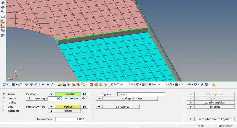
2) Click the "Connector" option under which "1D" main menu panel, Select the seam option under the "Connector" panel, set the element type which is "Quads". Selecting the nodes by using node path selection and also select the respective components for which creating the quads elements between them.
3) Provide the spacing distance which is 4mm, it means quad element size.
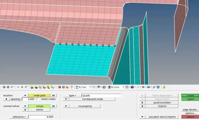
4) Click the create option to which creating the connector between them. After creating the connector, a elements are destroyed little bit. We have to work on it for capturing the proper mesh.
5) In this case, a connector element is created at exactly perpendicular to the surface.
4) Creating a connector between Front truss 2, Front truss 1 & Right Rail :
1) We have to Create a connector between Front truss 2, Front truss 1 & Right Rail 1 by using Spot weld with 3 layers and 5mm Diameter.
2) Go to "Connector" panel under which "1D" main menu panel, click the "Spot" option and select the element type which is "Weld". In this case, three component are comes to each other, so we increase number of layer from 2 to 3. We have to put the tolerance slightly higher than original distance between them.
3) Select the location which is nodes and selecting the nodes from where any one of the components edges which are presented. Put the diameter value which is 5mm and click to create the RBAR 1d element.
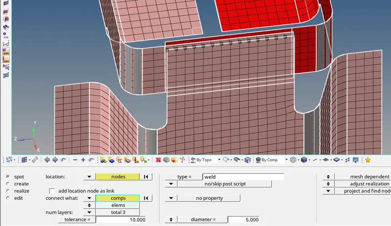
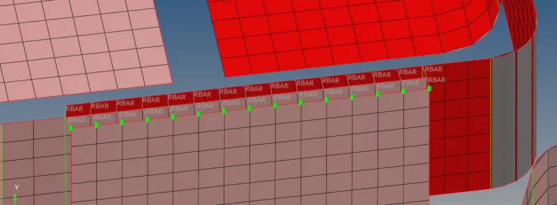
4) After click to creating, a RBAR elements are used to connecting the three component edges. A RBAR elements is used to connecting the two nodes to model a rigid welded type connection.
5) A connector part has looks like below image.
5) Create a connector between Front truss 2, Front truss 1 & Left Rail 1:
1) We have create a connector between the front truss 2, Front truss 1 & Left rail 1 components by using the Hexa Adhesive element.
2) Go to connector option under the "1D" main menu option, followingly select the seam option and choose the type which is "Hexa Adhesive" element.
3) Selecting the two row of nodes and also select the appropriate components. Put the spacing distance for elements, give the tolarence range and width of the elements are 4mm.
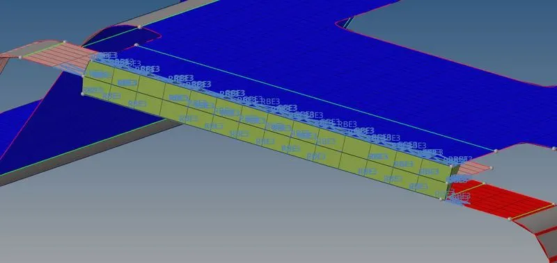
4) Click the create option which generating the combination of Hexa elements and RBE3 elements to connects the two components.
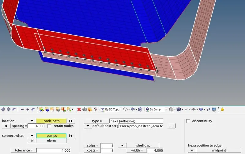
5) After Creation of Hexa adhesive elements for first two components, then gonna to bottom components to do similar manner.
6) A connectors are exactly looks like a below image.
6) Create a connector between Rear truss 2 & Right Rail 2 :
1) We have to create the connector between Rear truss 2 and Right rail 2 by using Bolt connector.
2) Go to connector option under which 1D main menu panel, choose the bolt option for creating the bolt connector between the components.
3) Select the node location and select the appropriate components and give the tolarence value which is 4mm and click to create the bolt connector.
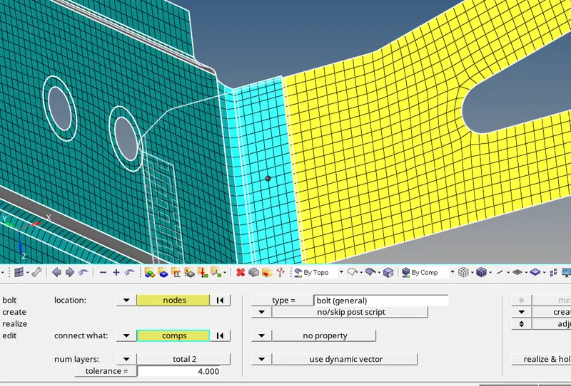
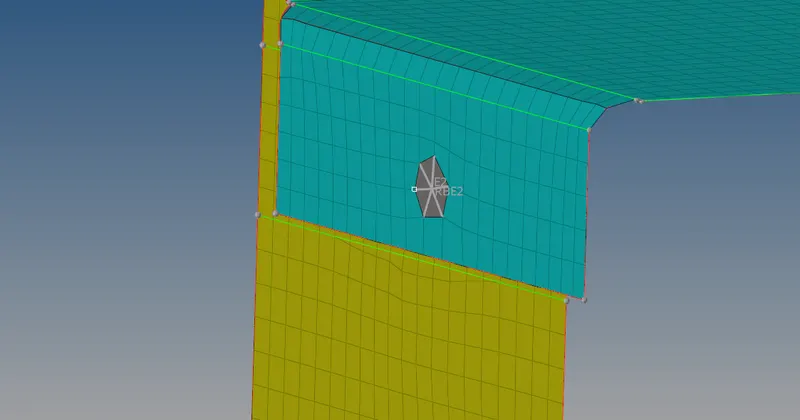
4) Hypermesh has creates the connector elements between the two components by using RBE2 1D element.
5) After creating the bolt connector between the components, a connection will looks like below image.
7) Create a connector between Rear truss 2 & Left Rail 2 :
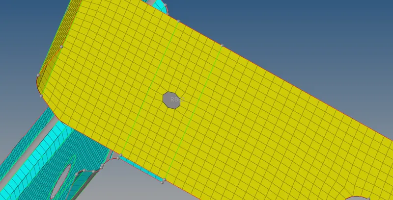
1) We have to create the connector between Rear truss & Left rail 2 by using bolt connector.
2) We use similar manner what we done at previous case for which to create the bolt connector between the two components.
8) Create a connector between Right rail 1 & Right rail 2 :
1) Creating a connector between the right rail 1& right rail 2 by using spot weld with rigid element.
2) Click the Connector option under the 1D element option, followingly select the spot option and choose the element type which is rigid. Give the tolerance value which is 10mm, select the nodes along the edges on both sides and click to generate the connectors between the respective components.
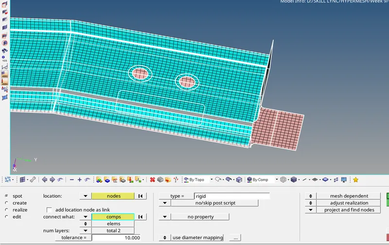
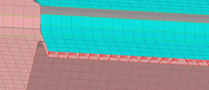
3) Hypermesh automatically creating the RBE2 1D elements between the components, because we already set into rigid elements.
4) A created rigid elements are looks like below image.
9) Create a connector between Left rail 1 & Left Rail 2 :
1) We have to create a connector between the left rail 1 & left rail 2 by using spot weld with spring elements.
2) Click the connector option under which 1D element main menu panel, followingly Click the spot option under the connector panel. Select the nodes along the length, choose the appropriate components as well and also give the tolerance value which is 10 mm.
3) Choose the connector element type which is "spring" and click a create option for generating the connector between them.
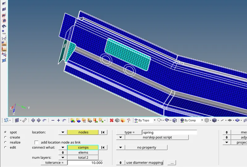
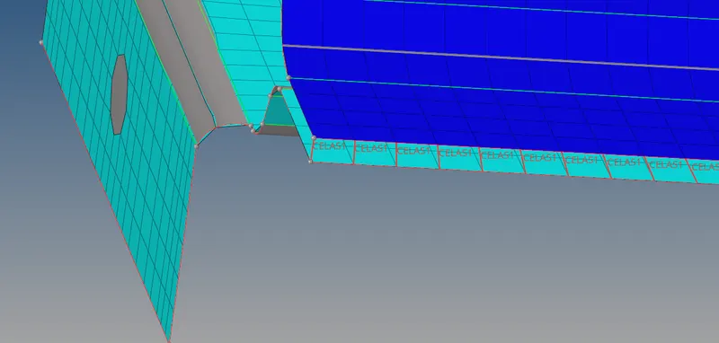
4) Hyper mesh have automatically creating the connector between them by using "CELAS1" element.
10) Create a connector between rest of the all components :
i) Create a connector between Reinforcement plate and Front truss 1 & 2:
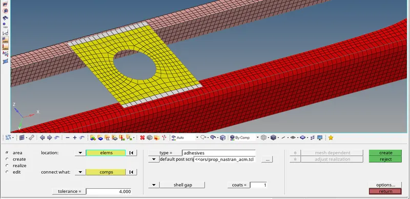
1) We have to create a connector between reinforcement plate and Front truss 1 & 2 by using area adhesives element.
2) Click the connector panel under the 1D option, choose the element type which is Adhesives. Selecting the elements, select the appropriate connects and give the tolerance value which is 4 mm.
3) Click the create option for generating the adhesive connector between them.
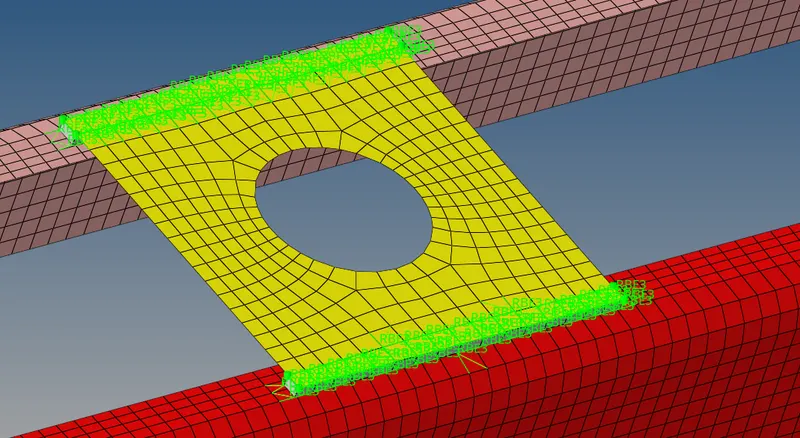
4) It will automatically creating the connector between them by using RBE3 link.
5) Below image shows after completion of area adhesive connector between them.
ii) Create a connector between Rear truss 1 & 2 :
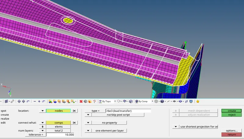
1) We have to create a connector between Rear truss 1& 2 by using rbe3 (load transfer) link.
2) Select the nodes along the edge on both side, then select the respective components to which generate the connectors and give the tolerance value which is slightly higher than the original distance between components for realized the opposite nodes.
3) A Hypermesh generates the connectors by using rbe3 elements with load transfer.
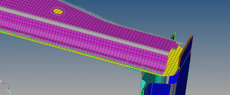
4) Similarly, create a connector between the rest of the components by using Rigidlnk and Quad as well.
FINAL MODEL IMAGE :
Successfully Created the all connectors which are given the challenge as well as rest of the parts in the model. After done all process, a model will looks like below image.