Create connectors for the model using Hypermesh
Aim:
To create connectors and Attach the various parts of the given model.
Objective:
1. Right_Rail_2 & Front_truss_1:- Seam-Quad(angled+capped+L)
2. Left_Rail_2 & Front_truss_1:- Quad elements
3. Front_truss_2, Front_truss_1 & Right_Rail_1:- Spot weld with 3 Layers and 5 mm Diameter
4. Front_truss_2, Front_truss_1 & Left_Rail_1:- Hexa (Adhesive)
5. Rear_truss_2 & Right_Rail_2:- Bolt Connector
6. Rear_truss_2 & Left_Rail_2:- Bolt Connector
7. Right_Rail_1 & Right_Rail_2:- Spot-weld with Rigid Elements
8. Left_Rail_1 & Left_Rail_2:- Spot-weld with Spring Elements
9. Rest all the component left Join them with suitable connectors
Introduction:
Connectors:
Connectors are geometric entities, which are primarily used to represent the CAD geometric connection in terms of FEA. Connections can be created as a spot-weld, seam-weld, adhesive, bolts and masses. A realized connector will be considered as the successful representation of a CAD model in preprocessing and the connecting parts can be considered as connected.
Seam Weld:
The process of joining the workpiece which is made of similar or dissimilar materials along a continuous seam is known as seam weld. In hypermesh, seam panels under connectors will help to represent the Seam weld connection between the components.
SpotWeld:
Spot welding is a resistance welding process that is used primarily for welding two or more metal sheets together by applying pressure and heat to the weld area. Heat for the welding process will be obtained from resistance to electric current. Realized spot weld in HyperMesh will represent the connection between the components.
Bolt Connection:
Bolted joints are one of the most common elements in construction and machine design. A connection between structural members made with plates and bolts, as opposed to a riveted or welded construction. In HyperMesh, we use the RBE2 elements to represent the Bolt connection, since it has more stiffness.
Procedure:
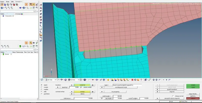
1. To create Seam-Quad(angled+capped+L) connection between Right_Rail_2 & Front_truss_1.
Select 1D/2D → Connectors → Seam option.
Now select the location, where the Weld has to be created, by clicking the “node list” select the nodes of the component and enter the tolerance value.
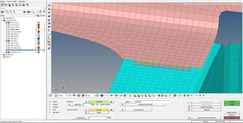
2. Create Quad elements between Left_Rail_2 & Front_truss_1.
Select 1D/2D → Connectors → Seam option and change the type as a quad and select the nodes of the component and enter the tolerance value.
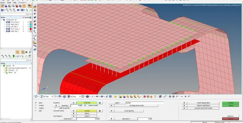
3. Create Spot weld with 3 Layers and 5 mm Diameter between Front_truss_2, Front_truss_1 & Right_Rail_1.
Select 1D/2D → Connectors → Spot option change the type as weld select the nodes of the component and enter the tolerance value.
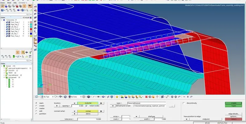
4. Create Hexa (Adhesive) between Front_truss_2, Front_truss_1 & Left_Rail_1.
Select 1D/2D → Connectors → Seam option change type as Hexa adhesive and select the nodes of the component and enter the tolerance value.
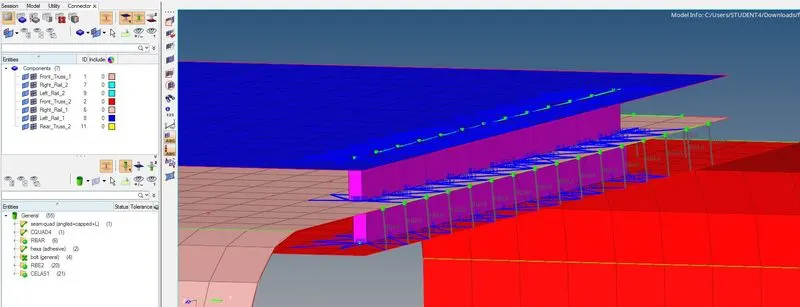
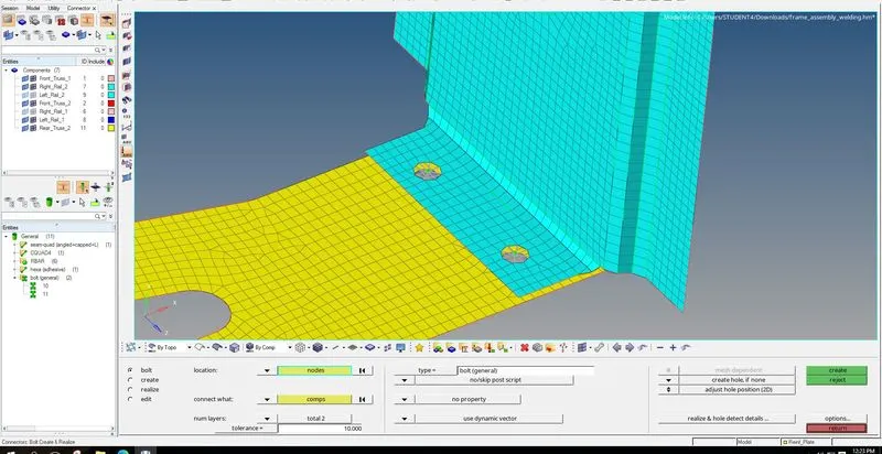
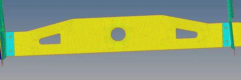
5. Create Bolt Connector between Rear_truss_2 & Right_Rail_2, Rear_truss_2 & Left_Rail_2.
Select the 1D/2D → Connectors → Bolt option and select the nodes of the component and enter the tolerance value.
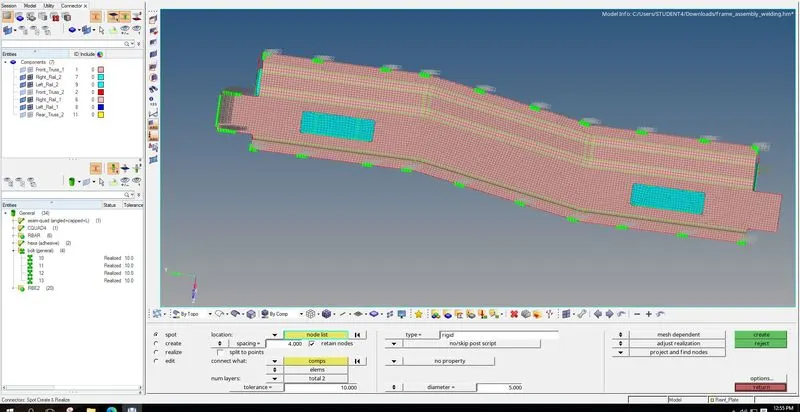
6. Create Spot-weld with Rigid Elements between Right_Rail_1 & Right_Rail_2.
Select 1D/2D → Connectors → Spot option change the type as rigid select the nodes of the component and enter the tolerance value.
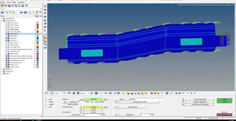
7. Spot-weld with Spring Elements between Left_Rail_1 & Left_Rail_2.
Select 1D/2D → Connectors → Spot option change the type to spring and select the nodes of the component and enter the tolerance value.
Result:
Conclusion:
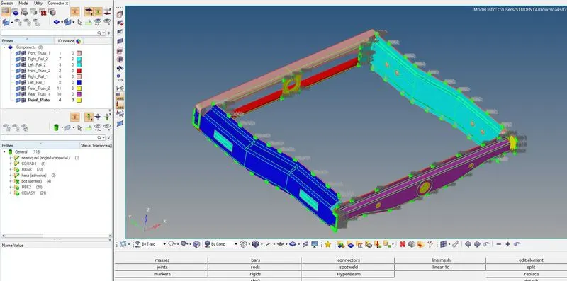
Applied the different type of connectors and appropriate actions to debug the failed and unrealized connectors and fixed it.
All the connectors are successfully created and realized while having the best possible mesh quality.
Different types of connectors that are available are learnt and some concepts associated with these connectors are learnt (such as cap angle, runoff
angle, weld angle, etc.
Reference:
Realizing Connectors in Hypermesh : Skill-Lync (skill-lync.com)