Connection deployment over Assemblies and Sub Assemblies using Hypermesh platform.
AIM:- Connection deployment over Assemblies and Sub Assemblies using Hypermesh platform.
OBJECTIVE:-
Extract Mid Surface from the Geometry
Mesh the MID surface with 2D Finite elements as per the Quality Criteria
Deploy a connection over different parts in the assembly. Check the realization of the deployed connection.
Given DATA & connection to deploy
Target Element length 5mm
3D model
1. Right_Rail_2 & Front_truss_1:- Seam-Quad(angled+capped+L)
2. Left_Rail_2 & Front_truss_1:- Quad elements
3. Front_truss_2, Front_truss_1 & Right_Rail_1:- Spot weld with 3 Layers and 5 mm Diameter
4. Front_truss_2, Front_truss_1 & Left_Rail_1:- Hexa (Adhesive)
5. Rear_truss_2 & Right_Rail_2:- Bolt Connector
6. Rear_truss_2 & Left_Rail_2:- Bolt Connector
7. Right_Rail_1 & Right_Rail_2:- Spot-weld with Rigid Elements
8. Left_Rail_1 & Left_Rail_2:- Spot-weld with Spring Elements
9. Rest all the component left Join them with suitable connectors
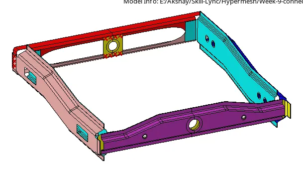
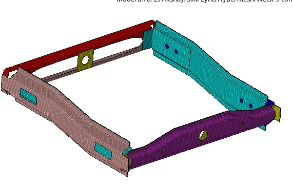
Geometry After the Meshing
Connections:-
It's an important step for Structural Analysis. In actual cases also the machine is made up of a number of components/ parts. All these parts/components are connected to each other by a Nut-bolt, seam/spot weld, or adhesive. All these come under the CONNECTORS in the Hypermesh. During analysis, these joints are an important factor because they are the only ones whos holding that component in its place. So the effect of vibration and deformation over this weld and bolt joint is also important. With the connectors, we can make an artificial weld/adhesive/bolt connection between the components and study the actual behavior of it during different sorts of analysis.
Connectors are geometric entities (not FE) primarily used to create spot and seam welds, but also used to create adhesives, bolts, and masses. They are simply a database of information defining specific requests for connections at specific locations. They are a medium to create both solver independent and/or solver dependent connections between geometric and/or FE entities
There is a color indicator to see either the connection is Failed, realized, or NOT.
RED:- Fail connection
Yellow:- Unrealized connections
Green :- Realized connection
1. Right_Rail_2 & Front_truss_1:- Seam-Quad(angled+capped+L)
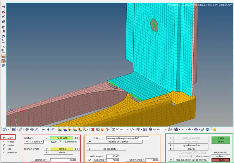
-First, go to the connectors --> Seam weld sub panel and select the type of weld you want to deploys over the respective parts, like to connects the parts you are seeing on the above image I have used the "Seam-Quad(angled+capped+L)" Type of Seam weld (orange window)
-To select the node there is an option called "location" from where you can select the node for deploying connections. we can select the components that we want to connect with each other using the "connect what" option. This subpanel asked us to define the "spacing" and "tolerance for the connection". In the tolerance, we can define the search distance and Hypermesh will search over the defined distance for elements capturing. (RED window)
-In the last section, we have to select the transition option for this I had selected the "quad transition with the imprint". We can also use the remesh and smooth option from the same subpanel. The remesh and smooth option just remesh and smooth the mesh over the dependent part (second selected part)
2. Left_Rail_2 & Front_truss_1:- Quad elements
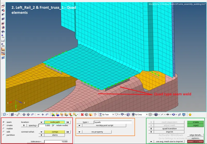
-First, go to the connectors --> Seam weld sub panel and select the type of weld you want to deploys over the respective parts, like to connects the parts you are seeing on the above image I have used the "Quad" Type of Seam weld (orange window). All other procedure for deploying the connector is same as seam quad. the only difference here was we selected the Type= Quad for seam connection.
3. Front_truss_2, Front_truss_1 & Right_Rail_1:- Spot weld with 3 Layers and 5 mm Diameter
1D Panel --> connectors --> Spot will lead you to this subpanel. In the location tab, you have to select the location of the connector to be created. There are different types of location defining methods like node, nodelist, line, and points.
For this assignment, I had preferred the Nodes option.
connect what: we can select the components that we want to connect with each other. I had selected all three components as you can see in the below image.
Num layers:- Define how many thicknesses have to be connected at connector position. there are three components to connect so I Had used the total3 option to capture three layers.
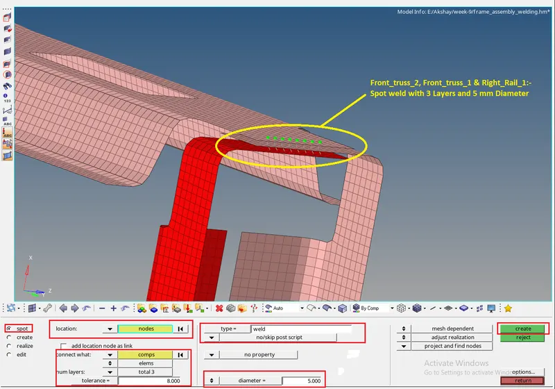
tolerance:- here we can define the search distance and Hypermesh will search over the defined distance for elements capturing.
Type:- here we can define which type of connection we want. there is a number of connection types available in each sub-panel. AS per our given task, we have to deploy spot weld so I had chosen the weld option from the Type tree.
Diameter:- it defines the weld nugget dia for spot weld. (given)
The4 mesh dependent/ adjust realization/project and find nodes are all options for the realization of the connectors. With these options, we can set connectors realization parameters, like if the mesh over the parent and child component is not equal we can set it to "adjust realization" & "project and find nodes" with that hypermesh automatically capture the nearest node and adjust the realization perfectly.
4. Front_truss_2, Front_truss_1 & Left_Rail_1:- Hexa (Adhesive)
1D Panel --> connectors --> Seam
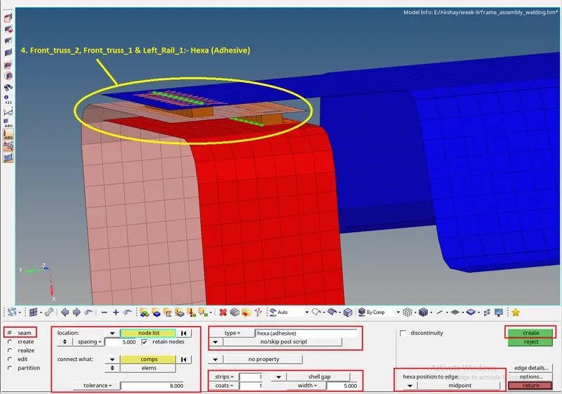
Location, tolerance, type selection is the same here as in the spot weld subpanel. the only thing added here is strips, coats, width. Again these option changes as per the Connection Type we select.
As you can see in the above image I had selected the "Hexa- adhesive" as a type here to deploy an adhesive type of connection and the option under the panel has changed accordingly.
If you compare it with the spot weld subpanel the area below the Type option will unlock new options as per the selected type. In the Spot weld panel, we only get to select the Dia of the weld nugget but in the Adhesive type of contact, we are getting options like the strips, coats, and width.
The Width is there to define the width of the adhesive element (Hexa), and the strip and coats decide the number of rows and columns in the connector entity.
5. Rear_truss_2 & Right_Rail_2:- Bolt Connector / 6. Rear_truss_2 & Left_Rail_2:- Bolt Connector
1D Panel --> connectors --> bolt
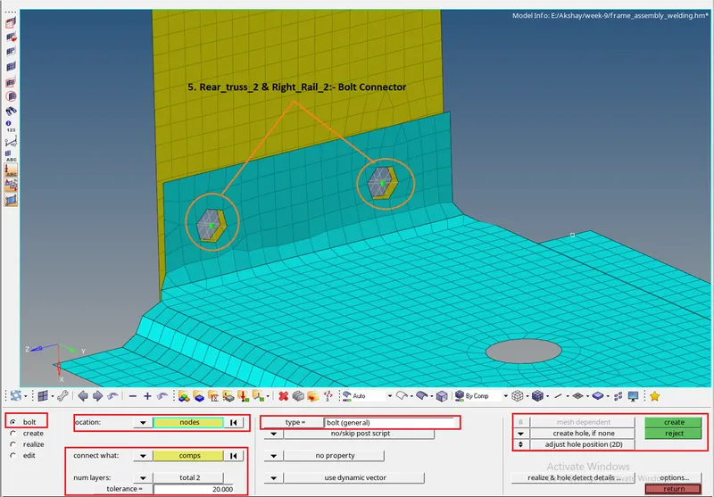
This option allow us to create the Holes and deploy bolt connection over the FE. the sub-panel is the same as the other type of connections.
We only have to select the position where we want to create the holes and want to deploy the proper bolt connection.
With this option either we can create a hole in the FE if there was no hole present or apply bolt connection if there is already a hole available. But to deploy the connection over the already existing hole it's important the node count over both holes are the same, otherwise, it will throw you an error.
7. Right_Rail_1 & Right_Rail_2:- Spot-weld with Rigid Elements + 8. Left_Rail_1 & Left_Rail_2:- Spot-weld with Spring Elements
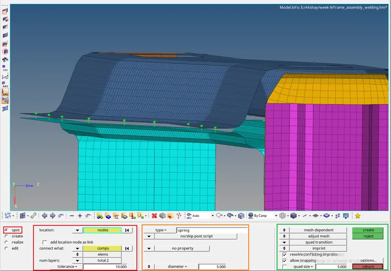
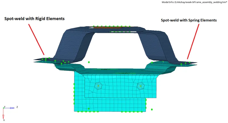
-the procedure is the same as the "Spot weld with 3 Layers and 5 mm Diameter", case 3 the only difference here is we are selecting Type as Rigid + Spring. The connectors are visually the same as you can see in the second image. these connectors are differed by the properties only.
-to get the connections normal to the adjacent component I had chosen the options in the green window (first image).
How to Identify the unrealize/fail connector and solve it?
-In hypermesh there is a special Browser available named "Connector browser", which will store the connector's data in it. Any connector entity you define is getting saved to the connector browser and we can edit it any time from the browser itself.
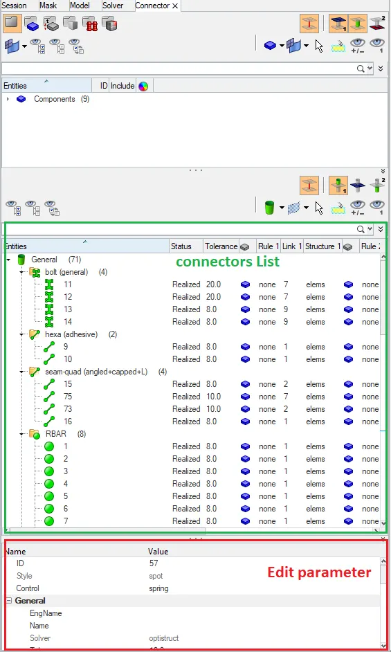
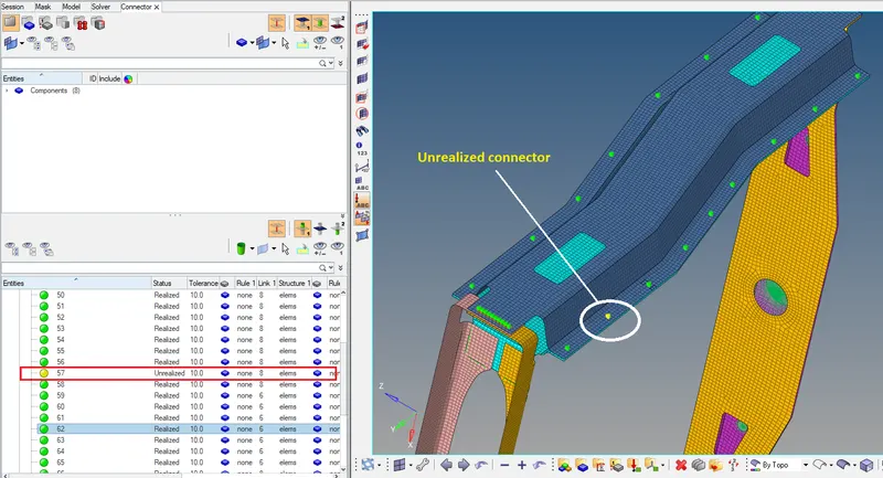
As you can see in the first image, the green box is showing the Connector list, from here you can check if the connectors are failing or not or what sort of problem happening over the connector. Like in the second image one spot weld is in Yellow color and as we discussed earlier this color indication is for the Unrealized connector, You can see that status on Graphics as well as connector browser window in hypermesh.
You can Edit the parameter to make the connector realize and right-click on the connector and go for the realize to make it realize by updating the staus.
9. Rest all the component left Join them with suitable connectors
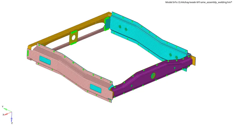
For the rest of the components, I had given the Spot weld connection. In some areas near the hole, I had deployed the RBE2 cluster connections.
Conclusion:-
1) Connectors are geometric entities & not FE which are primarily used to create spot and seam welds, adhesives, bolts, and masses. They are different from the 1D elements like spring, beam, rod, etc.
2) For a structural Analysis all the components should be connected with the proper Connector entities with the proper properties assing.
3)To connect the holes with the bolt connector the node count on the respective holes should be the same