Creating connectors between frame assembly components
Objective:
We are given a frame assembly model consisting of nine individual components as shown below.
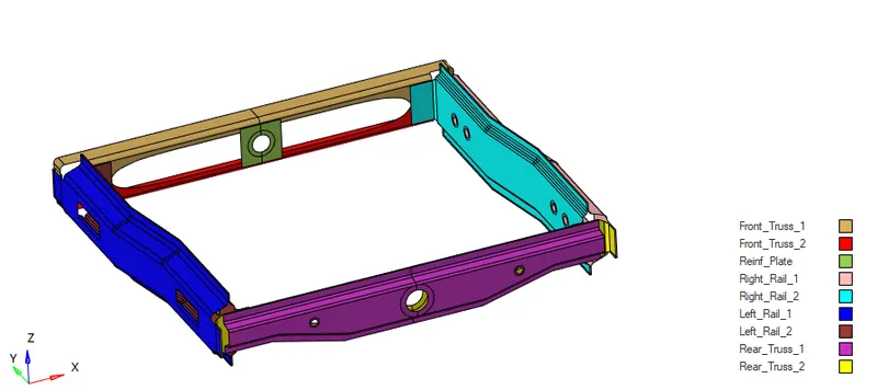
The objective here is to mesh and create connectors for this given assembly as specified below:
- Right_Rail_2 & Front_truss_1:- Seam-Quad(angled+capped+L)
- Left_Rail_2 & Front_truss_1:- Quad elements
- Front_truss_2, Front_truss_1 & Right_Rail_1:- Spot weld with 3 Layers and 5 mm Diameter
- Front_truss_2, Front_truss_1 & Left_Rail_1:- Hexa (Adhesive)
- Rear_truss_2 & Right_Rail_2:- Bolt Connector
- Rear_truss_2 & Left_Rail_2:- Bolt Connector
- Right_Rail_1 & Right_Rail_2:- Spot-weld with Rigid Elements
- Left_Rail_1 & Left_Rail_2:- Spot-weld with Spring Elements
- Rest all the component left Join them with suitable connectors
Procedure:
Connectors are finite element entities that define connections between other entities. And are used to make connections between two components. There are many connectors available in Hypermesh under the connectors tool panel like spot welds, rivets, bolts, seam welds, adhesives, etc. The process of creating connectors in Hypermesh starts from selecting the nodes/elements where the connector is to be deployed, then selecting the components, then selecting the type of connector, and finally creating and realizing it. After creating the connector, if the color of the connector is green then it means it is realized and if it is red, then it means there is some error and it is not realized.
First, the midsurfaces of the components need to be meshed, which is already extracted for all the components. All the components are meshed using the automesh tool with an element size of 5mm and element size set to mixed and the created mesh is accepted.
Now, we can start adding connectors.
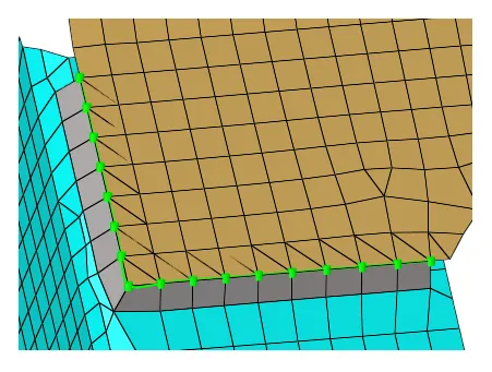
1. Seam-Quad (angled+capped+L)
First Right_Rail_2 & Front_truss_1 are isolated. The connector is created by going to 1D>connectors>seam.
- Nodes are selected on Front_truss_1
- Spacing: 5
- Retain nodes is checked
- Both components are selected under connect what
- Tolerance: 10
- Seam-Quad (angled+capped+L) is selected as the type
The created connectors are shown in the image below.
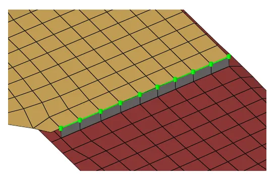
2. Quad
Again, Left_Rail_2 & Front_truss_1 are isolated first. This connector is also available at 1D>connectors>seam.
- Nodes are selected on Front_truss_1
- Spacing: 5
- Retain nodes is checked
- Both components are selected under connect what
- Tolerance: 10
- Quad is selected as the type
The created connectors are shown in the image below.
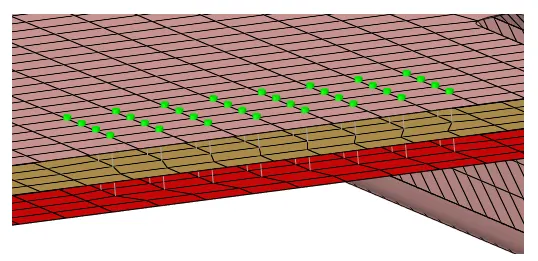
3. Spot weld
Again, Front_truss_2, Front_truss_1 & Right_Rail_1 are isolated first. The connector is created by going to 1D>connectors>spot.
- Nodes are selected on Right_Rail_1
- All three components are selected under connect what
- number of layers is changed to 3
- Tolerance: 10
- Weld is selected as the type
- diameter is set to 5mm
- Mesh dependent>adjust mesh>remesh configuration is selected to get smooth mesh after the connection is made
The created connectors are shown in the image below.
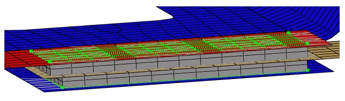
4. Hexa (adhesive)
Again, Front_truss_2, Front_truss_1 & Left_Rail_1 are isolated. The connector is created by going to 1D>connectors>area. This connector is created first between Left_Rail_1 & Front_truss_1 and then between Front_truss_2, Front_truss_1.
Tolerance is set to 10mm and the number of coats is set to 2. The created connectors are shown in the image below.
5 & 6. Bolts
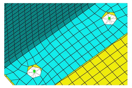
Again, Rear_truss_2 & Right_Rail_2 are isolated first. The connector is created by going to 1D>connectors>bolt.
- Two nodes are selected on Right_Rail_2
- Both components are selected under connect what
- Tolerance: 10
- Bolt (general) is selected as the type
- Create hole, if none configuration is selected as there is no previous hole to add the connector
Similarly, it is created for Rear_truss_2 & Left_Rail_2. The created connectors are shown in the image below.
7. Spot-weld with Rigid Elements
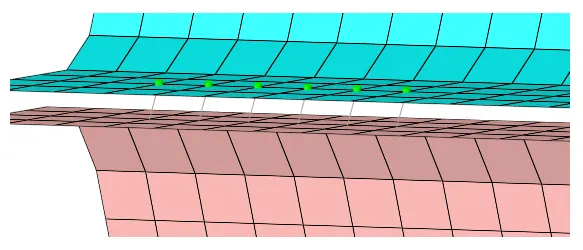
Again, Right_Rail_1 & Right_Rail_2 are isolated first. The connector is created by going to 1D>connectors>spot.
- Nodes are selected by path on Right_Rail_2
- Both components are selected under connect what
- Tolerance: 10
- rigid is selected as the type
- diameter is set to 5mm.
- Mesh dependent>adjust mesh>remesh configuration is selected
Few of the created connectors are shown in the image below.
8. Spot-weld with Spring Elements
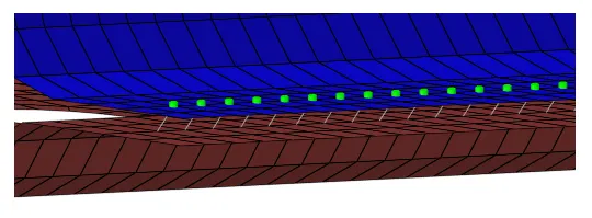
Again, Left_Rail_1 & Left_Rail_2 are isolated first. This connector is also created by going to 1D>connectors>spot.
- Nodes are selected by path on Left-Rail_1
- Both components are selected under connect what
- Tolerance: 10
- spring is selected as the type
- diameter is set to 5mm.
- Mesh dependent>adjust realization>project & find nodes configuration is selected, using this configuration, Hypermesh will project the element and connect to the nearest node instead of remeshing.
Few of the created connectors are shown in the image below.
Finally, the remaining components are also connected in the same way.
Conclusion:
Connectors are essentially 1D elements used to connect two components. They are created after meshing the components. After adding the connectors, sometimes the mesh gets distorted and should be re-meshed for that region.