Week 9-Challenge
AIM:To get a proper 2D mesh flow along with the different connections deployement at the different parts of the component which is suited at different position.
PROCEDURE:(I)The model is in the form of mid surfacing of the main model, we directly deployed a mesh with element size is 5mm with very less trias and no rotating quads,firstly the model has shown below which is being provided.
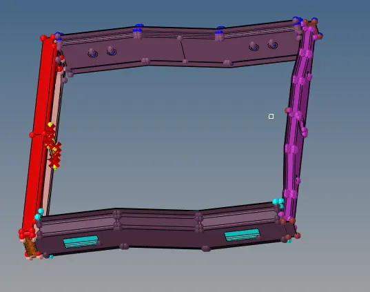
And the model what has became after deployment of the mesh as shown below:
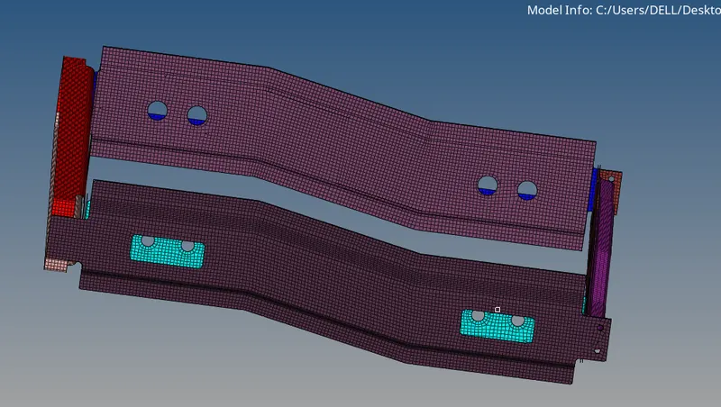
(II)After meshing certain connection that has been deployed whose steps are as follows:
1. Right_Rail_2 & Front_truss_1:- Seam-Quad(angled+capped+L)
2D>connectors>seam, under TYPE >Seam-Quad(angled+capped+L)
shown below in the form of images:
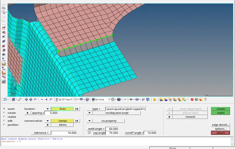
Spacing and tolerance can distort the mesh drastically so proper values needs to be assigned along with remeshing the areas which has been disturbed by the connections.
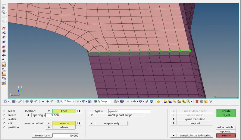
2. Left_Rail_2 & Front_truss_1:- Quad elements.
2D>connectors>seam, under TYPE>Quad elements
image will show the details mentioned above:
3. Front_truss_2, Front_truss_1 & Right_Rail_1:- Spot weld with 3 Layers and 5 mm Diameter.
2D>connectors>spot with dia. is 5mm and tolerance is 10mm with no. of layors are 3.
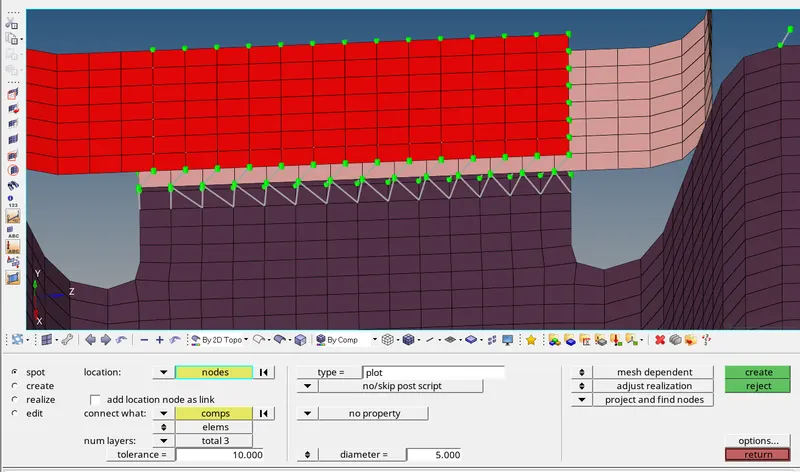
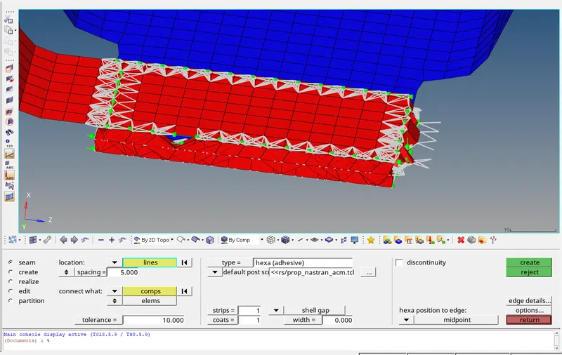
4. Front_truss_2, Front_truss_1 & Left_Rail_1:- Hexa (Adhesive)
2D>connectors>seam, under TYPE>HEXA(ADHESIVE)
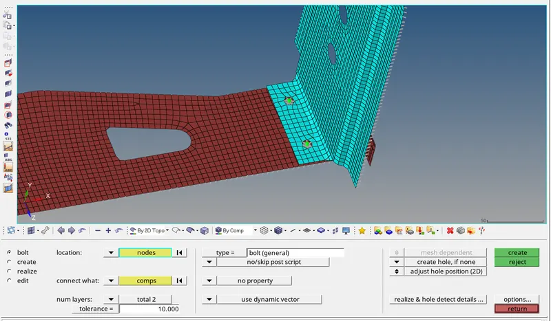
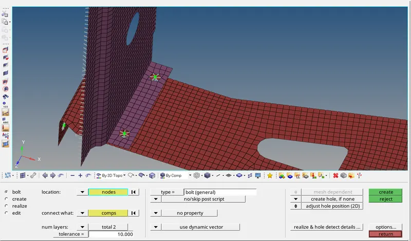
5. Rear_truss_2 & Right_Rail_2:- Bolt Connector.
and 6. Rear_truss_2 & Left_Rail_2:- Bolt Connector.
2D>connector>bolt,under type bolt(general)
here we have got to choose for the create hole,if none otherwise we will not get the hole of RBE2 connection with the respective layors and tolerances shown below:
7. Right_Rail_1 & Right_Rail_2:- Spot-weld with Rigid Elements.
2D>connectors>spot,Type>rigids.
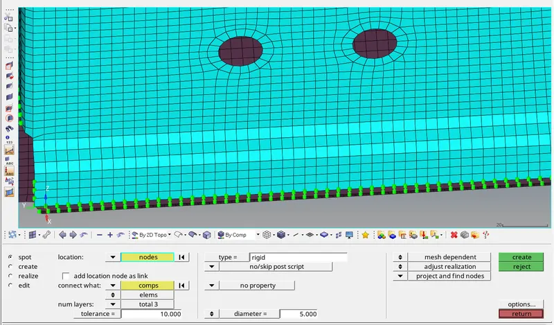
8. Left_Rail_1 & Left_Rail_2:- Spot-weld with Spring Elements.
2D>connectors>spot,Type>spring.
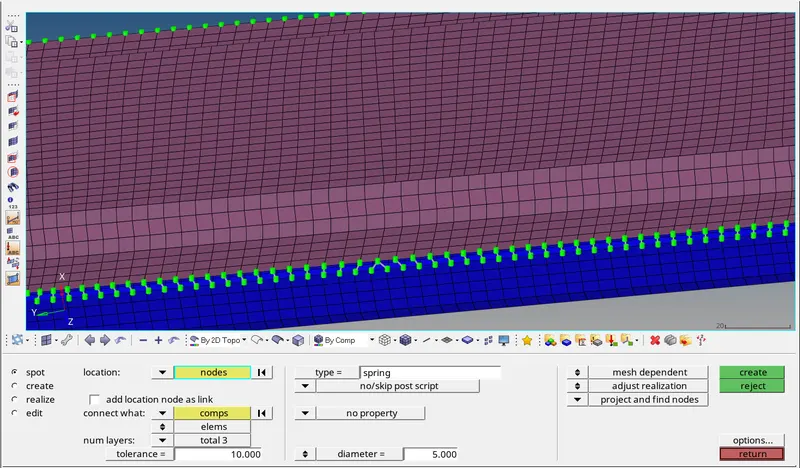
9. Rest all the component left Join them with suitable connectors.
The connections where left out at the plate region with front truss_1 and front truss_2 there we can deployed a spot weld as well in order to make the connection in between shown below:
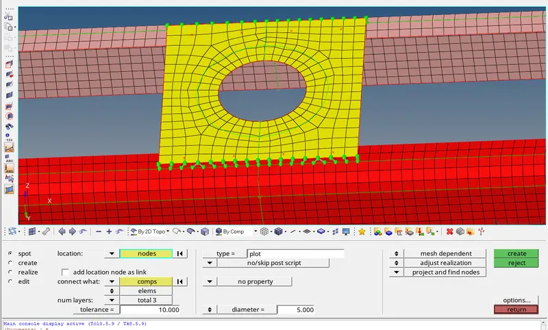
Likewise many other region could be connected either by bolts or spot weld or different seam weld wherever it is required or where 2 surfaces are parallel or perpendicular and very close to each other is being connected by connectors.
All the connection can be visualised by VIEW>BROWSER>HYPERMESH>CONNECTOR where whatever connection has been deployed can be seen separately.
CONCLUSION:Geometric entities that define connections between other entities
• Used for welding, bolts, adhesives, etc.
• Link geometry or FE entities
• Can be “realized” into FE representations of welds, etc. for any supported solver
• rigids, CWELDs, MAT100s, ACMs, etc.
• Creation of FE welds, bolts, adhesives, etc.
• interactively or from:
(1) XML file
(2) MCF (master connectors file)
(3)Spot welds only
• Switching between different FE configurations of
welds, bolts, adhesives, etc.
Here we have got to know about the connectors connections and it's working with precision whether it is in term of type or different property implication.