Week 9-Challenge
Creating Connectors between various Parts in Frame Assembly using Hyper Mesh
Aim
Create Connections between Various Parts of the given Frame assembly model
What are Connectors?
Connectors are geometric entities, which are primarily used to represent the CAD geometric connection in terms of FEA. Connections can be created as a spot-weld, seam-weld, adhesive, bolts and masses. A realized connector will be considered as the successful representation of a CAD model in preprocessing and the connecting parts can be considered as connected.
Procedure
1) Import the given frame assembly model,
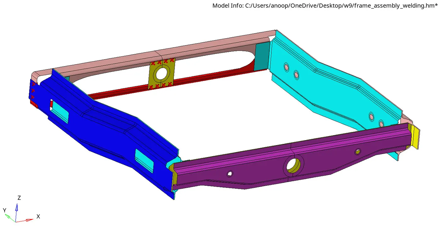
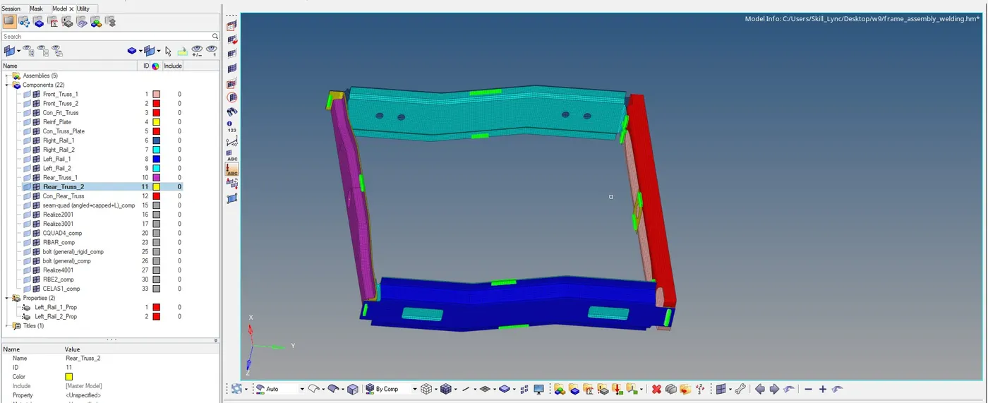
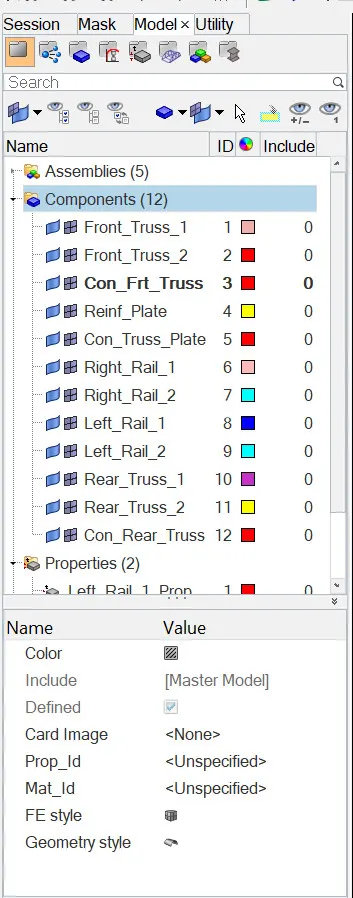
Components present in the model
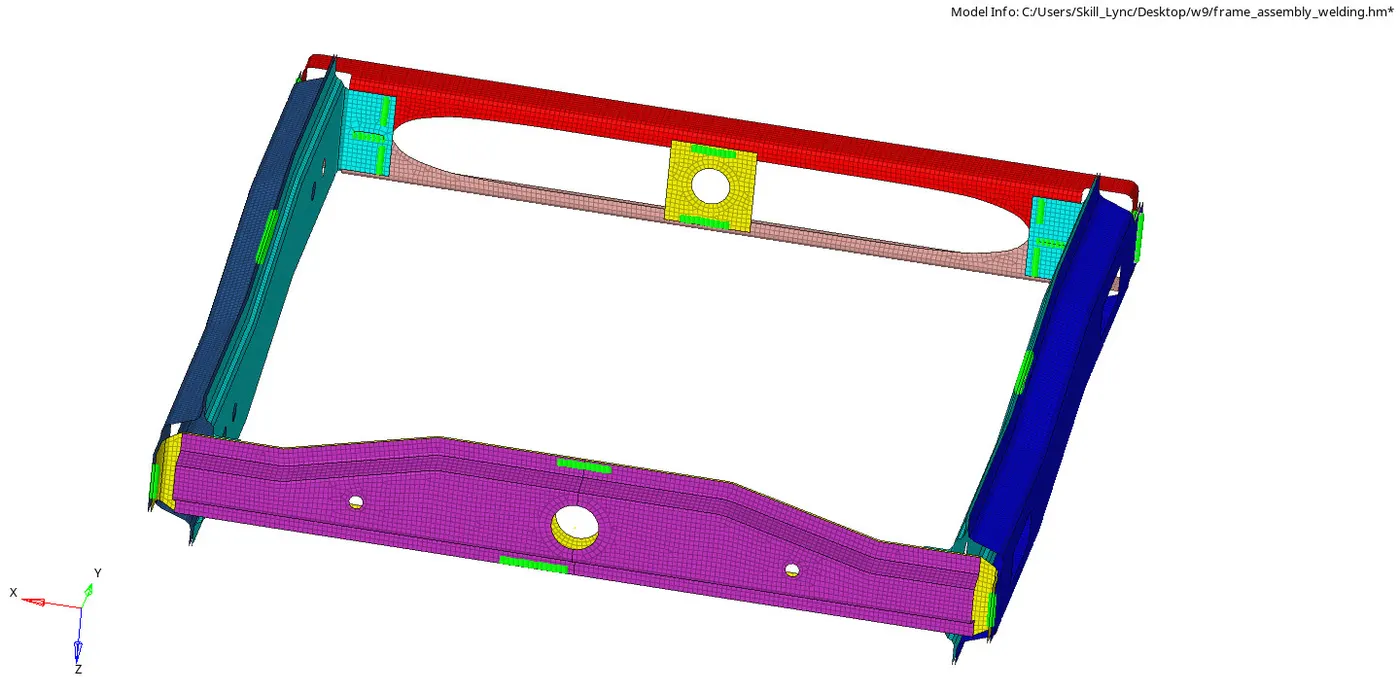
2) Meshed the component using 2D -> Automesh -> select the surface and create mesh with appropriate element size
Creating Seam weld connectors
The process of joining the workpiece which are made of similar or dissimilar materials along a continuous seam is known as Seam weld.
In hypermesh, seam panels under connectors will help to represent the Seam weld connection between the components.
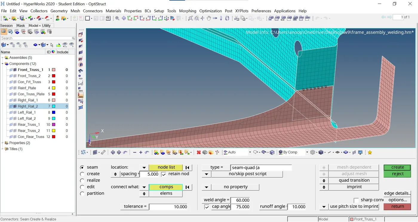
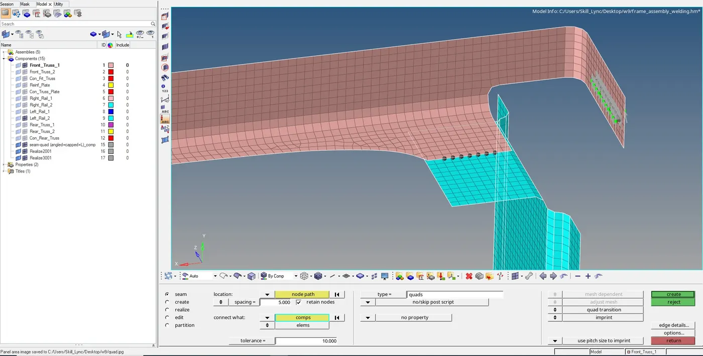
Steps to be followed to create Seam - Quad (angled+Capped+L) Weld:
- Select 1D/2D → Connectors → Seam option.

- Now select the location, where the Weld has to be created, by clicking the “node list”.
- Tick the checkbox of “retain nodes” option, to retain the position of the nodes, while creating and realizing a connector.
- Specify the “spacing” value and select the “comps” option under “connect what”, in order to create the weld between those two components.
- Specify the “tolerance” value, based on the distance between the two components.
- Select the type as “seam-quad (angled+capped+L)”.
- Click on the “create” button, to create the seam weld

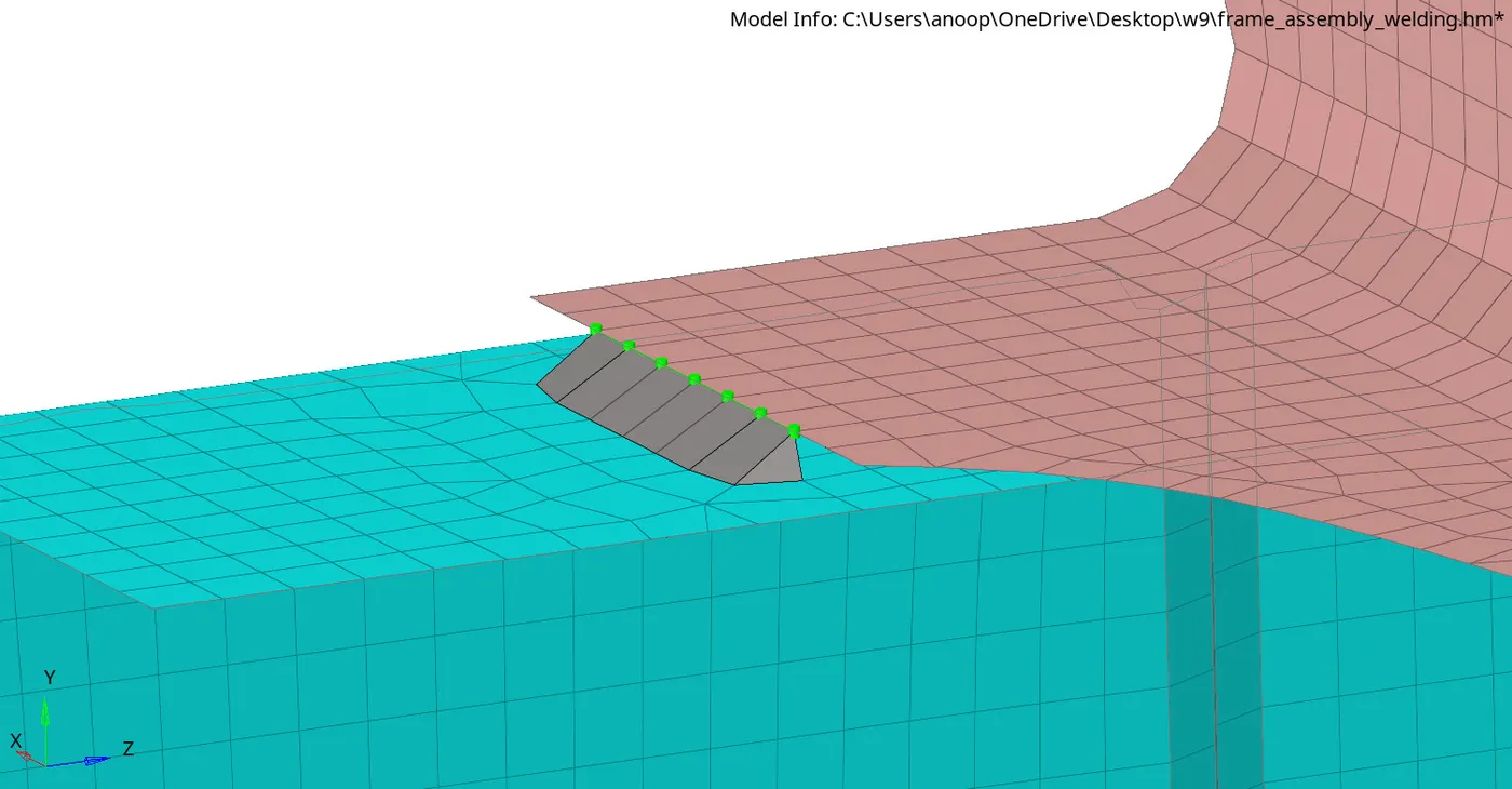
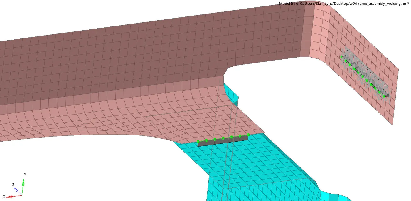
Seam Weld connector after realization
Creating Seam - Hexa Adhesive Weld:
- Select 1D/2D → Connectors → Seam option.
- Now select the location, where the Weld has to be created, by clicking the “node list”.
- Tick the checkbox of “retain nodes” option, to retain the position of the nodes, while creating and realizing a connector.
- Specify the “spacing” value and select the “comps” option under “connect what”, in order to create the weld between those two components.
- Specify the “tolerance” value, based on the distance between the two components.
- Select the type as “hexa (adhesive)”.
- Click on the “create” button, to create the seam weld

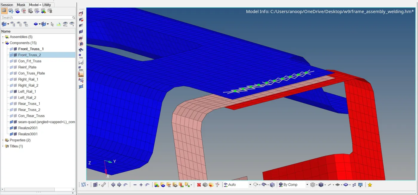
Seam - Hexa Adhesive Weld after Realization
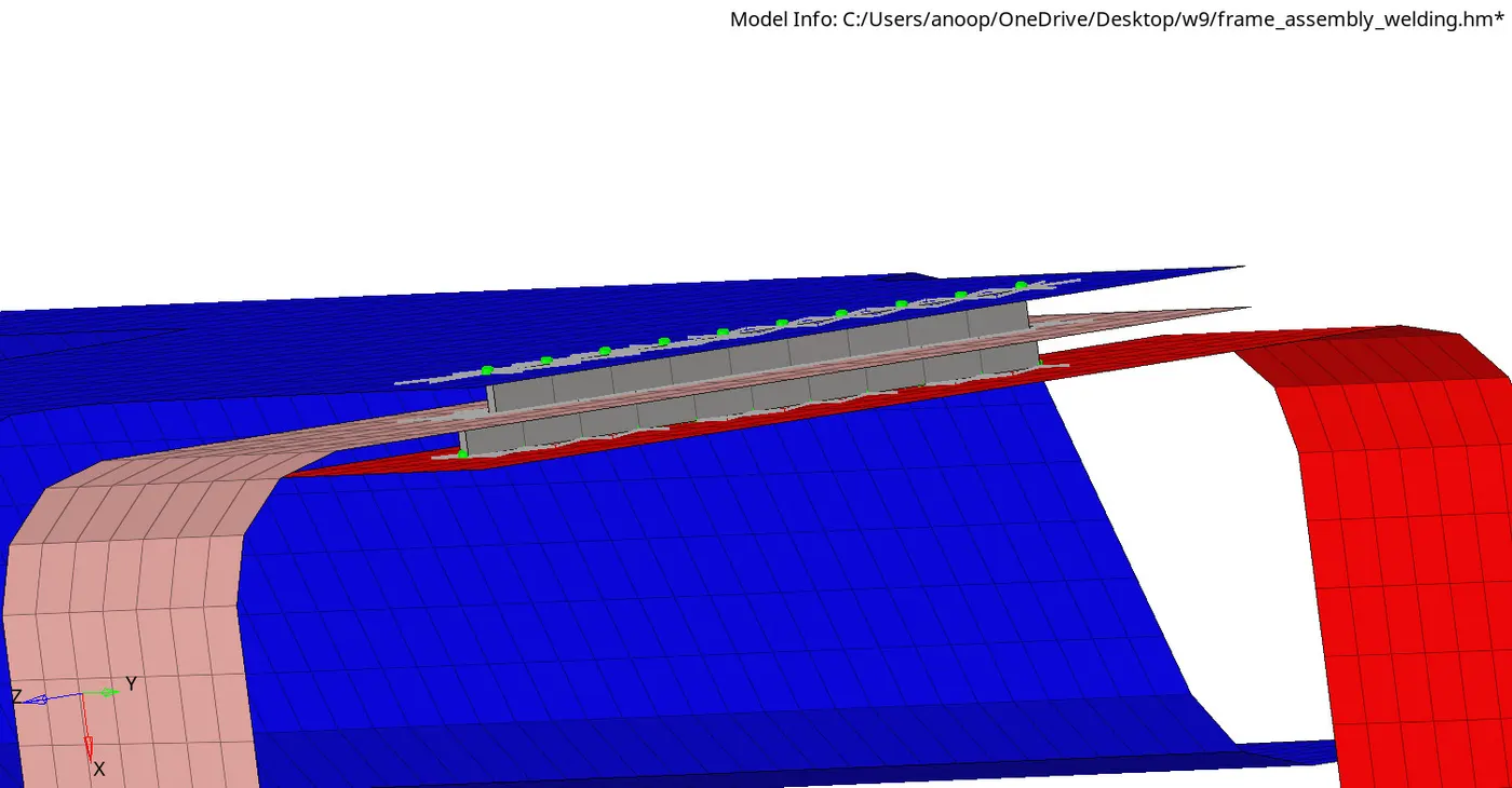
Similarly Created Seam weld using quad elements

Creating Spot Weld Connector
Spot Weld:
Spot welding is a resistance welding process that is used primarily for welding two or more metal sheets together by applying pressure and heat to the weld area. Heat for the welding process will be obtained from resistance to electric current.
Realized spot weld in HyperMesh will represent the connection between the components.
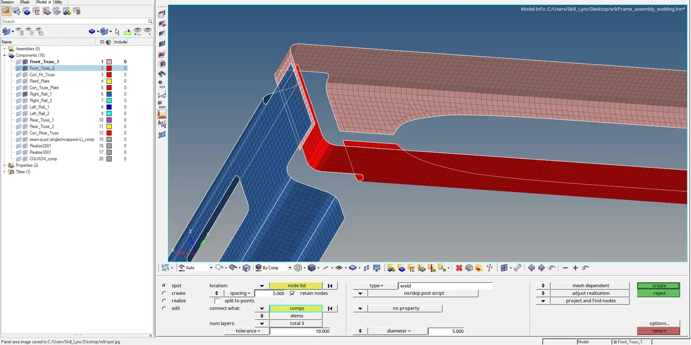
Steps to be followed to create Spot Weld:
- Select 1D/2D → Connectors → Spot option.
- Now select the location, where the Weld has to be created, by clicking the “node list”.
- Tick the checkbox of “retain nodes” option, to retain the position of the nodes, while creating and realizing a connector.
- Specify the “spacing” value and select the “comps” option under “connect what”, in order to create the weld between those two components.
- Select the number of layers(Number of Components) to be welded, under “num layers” option.
- Specify the “tolerance” value, based on the distance between the two components.
- Select the type as “weld”.
- Click on the “create” button, to create the spot weld

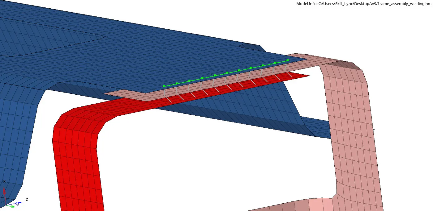
Realized Spot Weld Connection
Creating Bolt Connector
Bolt Connection:
Bolted joints are one of the most common elements in construction and machine design. A connection between structural members made with plates and bolts, as opposed to a riveted or welded construction. In HyperMesh, we use the RBE2 elements to represent the Bolt connection, since it has more stiffness.
A. Steps to be followed to create Bolt connection:
- In order to create a Bolt connection, if we had hole present in the components, we have to locate a centre node, or by selecting the option “create hole, if none”, from the default option, this option will create a hole in the mesh, if there is no pre-existing hole in the model.
- Now click on the 1D/2D → Connectors → Bolt option.
- Under “location”, select the node, which we created already to establish the bolt connection.
- Then select the “comps” option under “connect what”, in order to create the weld between those two components.
- Select the number of layers to be welded, under “num layers” option.
- Specify the “tolerance” value, based on the distance between the two components.
- Select the type as “bolt (general)”.
- Click on the “create” button, to create the seam weld

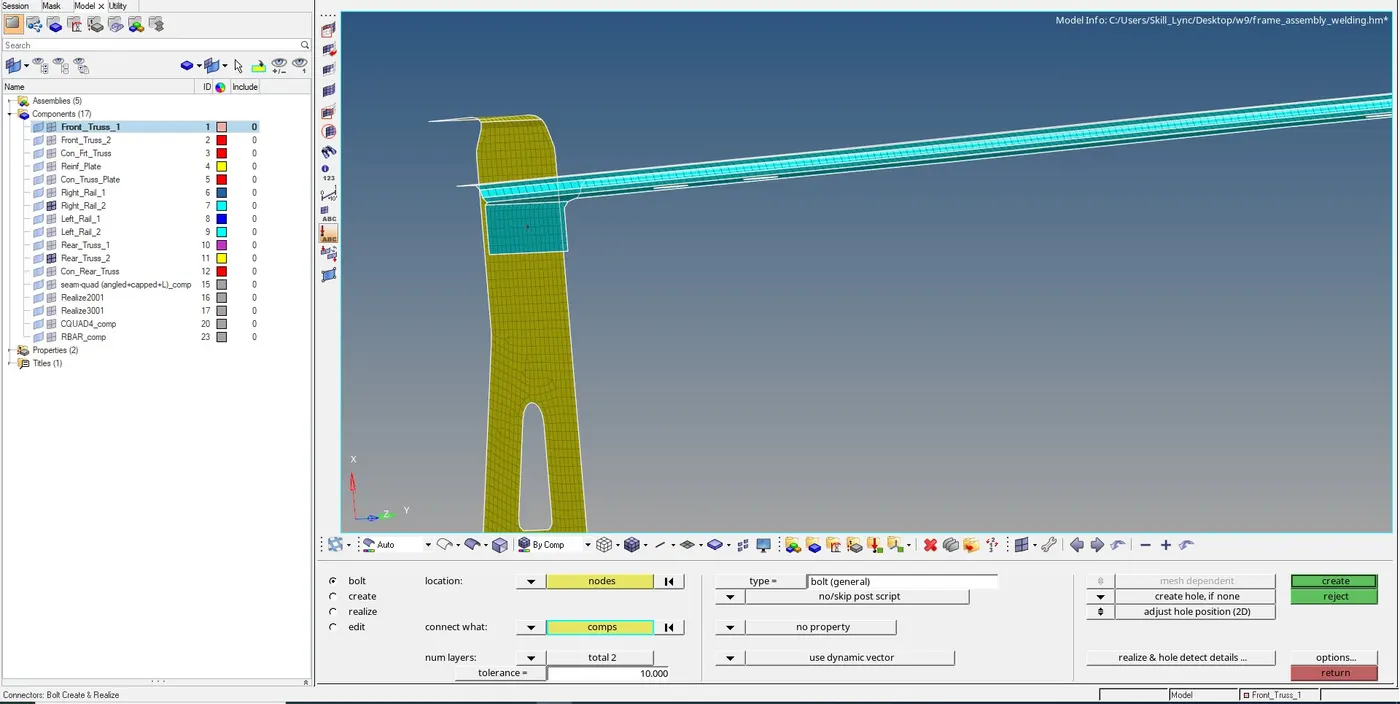
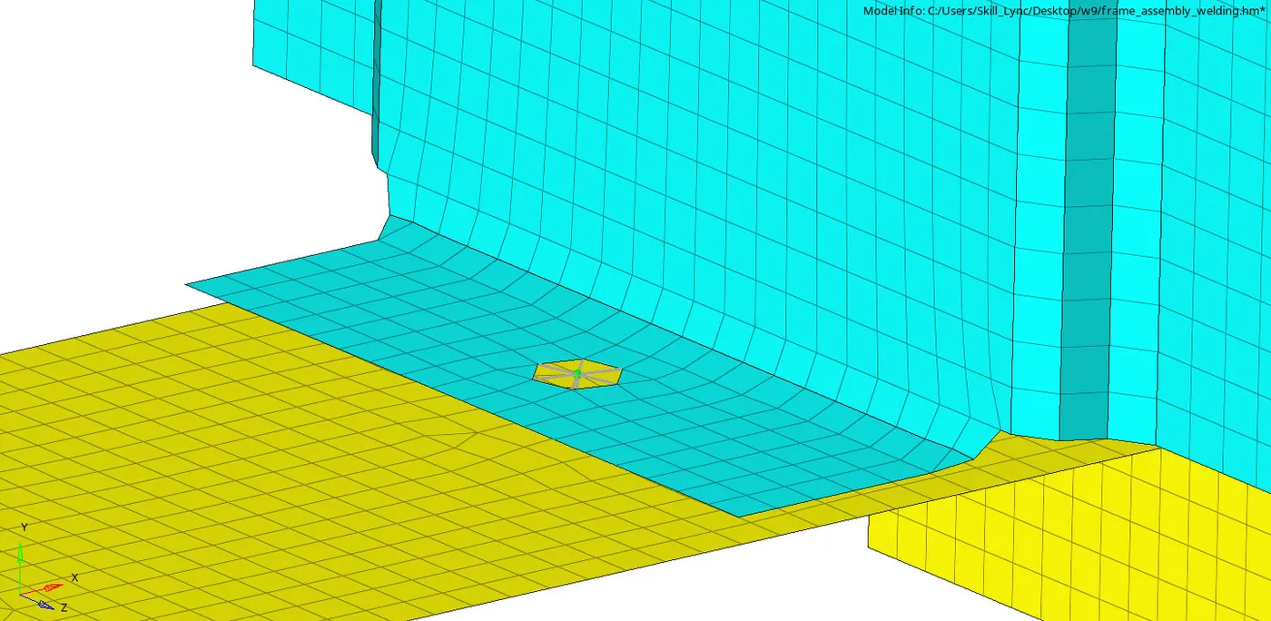
Realized Bolt Connection
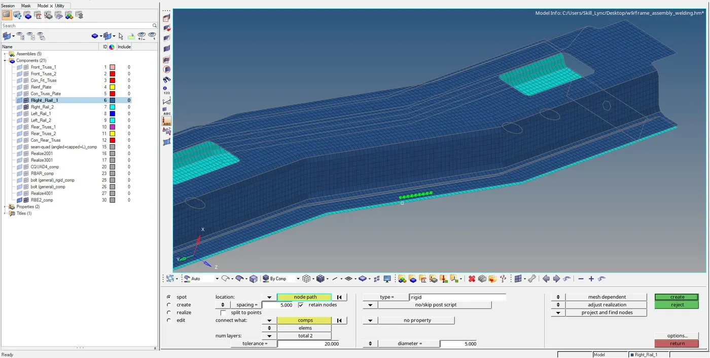
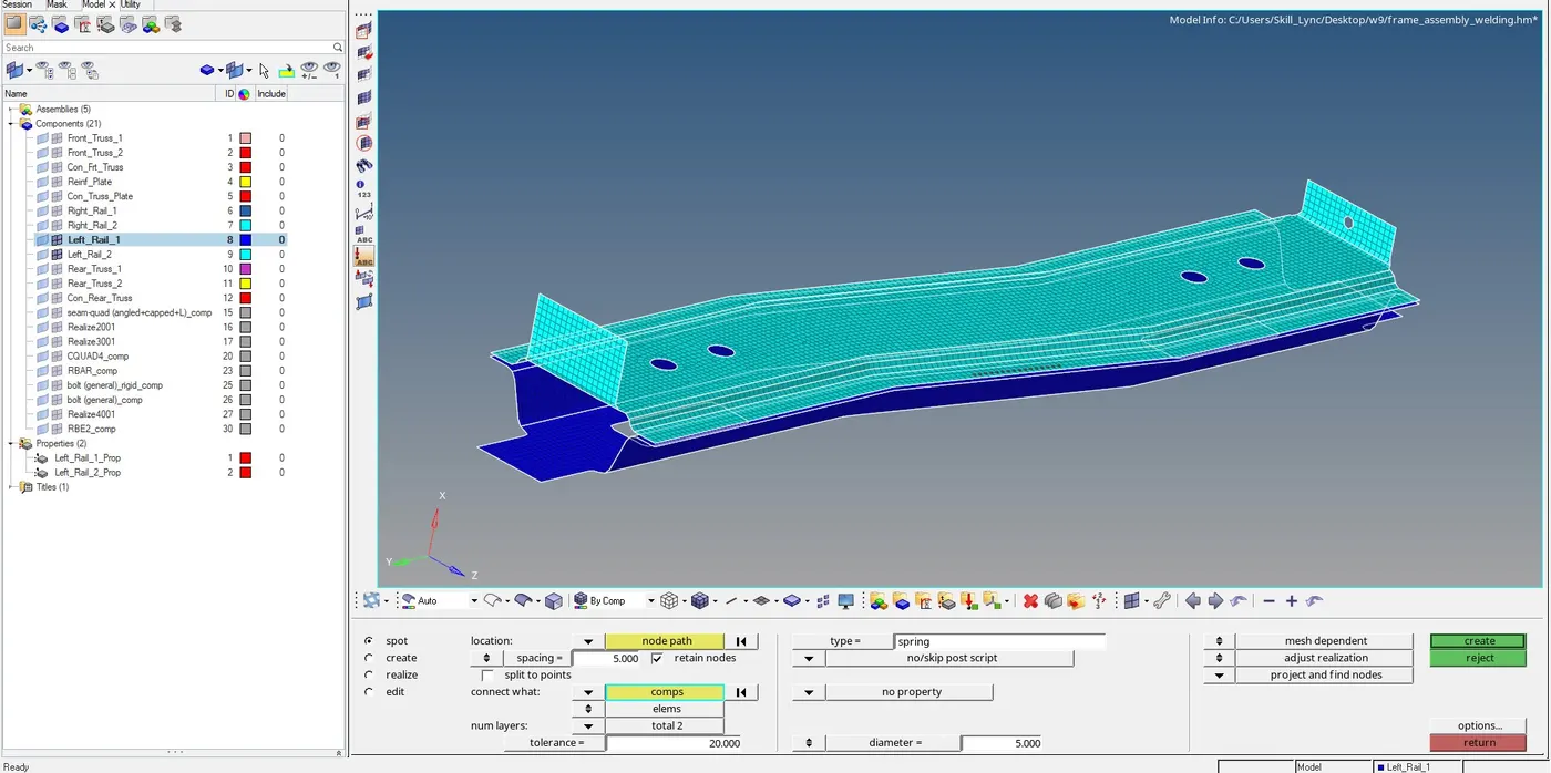
Steps to be followed to create Spot Weld ( with rigid and spring elements )
- Select 1D/2D → Connectors → Spot option.
- Now select the location, where the Weld has to be created, by clicking the “node list”.
- Tick the checkbox of “retain nodes” option, to retain the position of the nodes, while creating and realizing a connector.
- Specify the “spacing” value and select the “comps” option under “connect what”, in order to create the weld between those two components.
- Select the number of layers(Number of Components) to be welded, under “num layers” option.
- Specify the “tolerance” value, based on the distance between the two components.
- Select the type as “rigid or spring as per requirement
- Click on the “create” button, to create the spot weld
Spot weld with rigid Elements

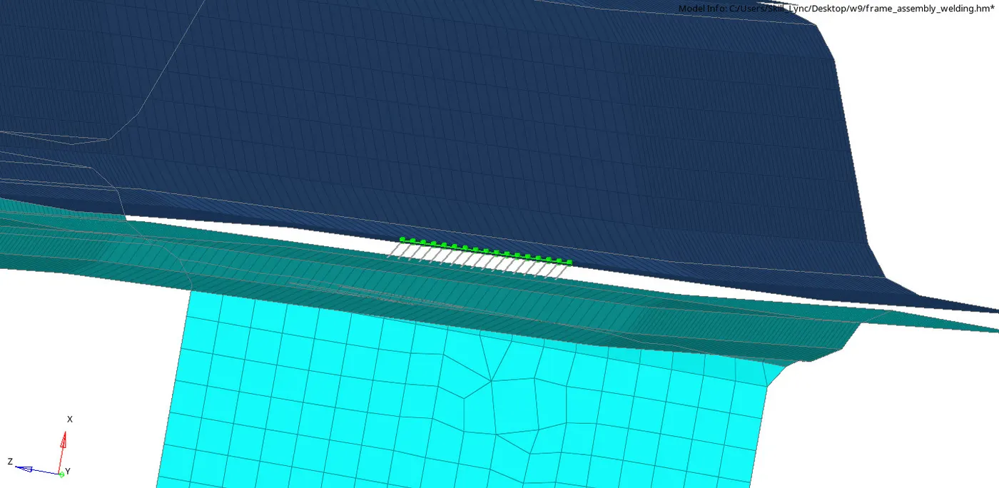
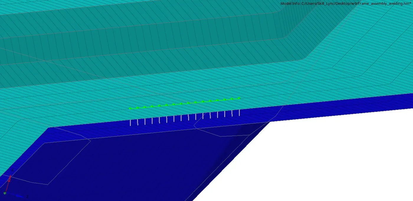
Spot weld with Spring elements

Result
Created Appropriate Connections between different components in frame assembly model.
Final model with appropriate connectors