Week 9 - Challenge 1 - Base Bracket Design
Base Bracket Design
AIM:
To create the part of the Base Bracket plastic component through a given Class A surface and to perform Draft Analysis of the final element.
Class A Surface:
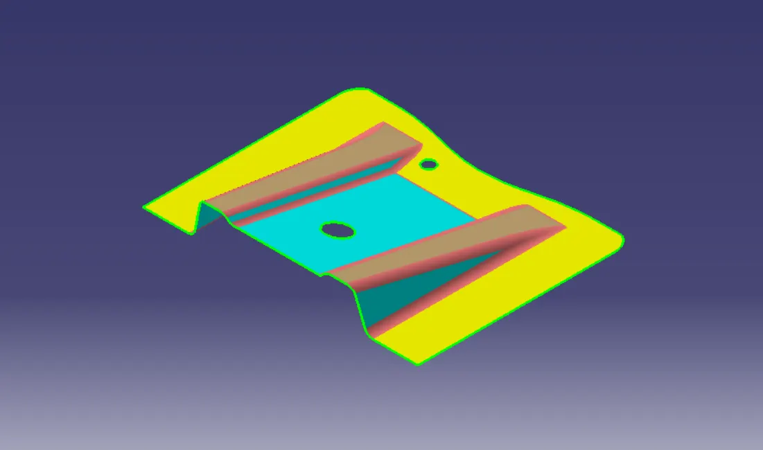
The surface is created by the concept sketches made by freehand sketches. The finalised sketch is then fed to the computer and a 2D surface is created out of it by the use of a software like Alias. This computerized design is known as Class A surface.
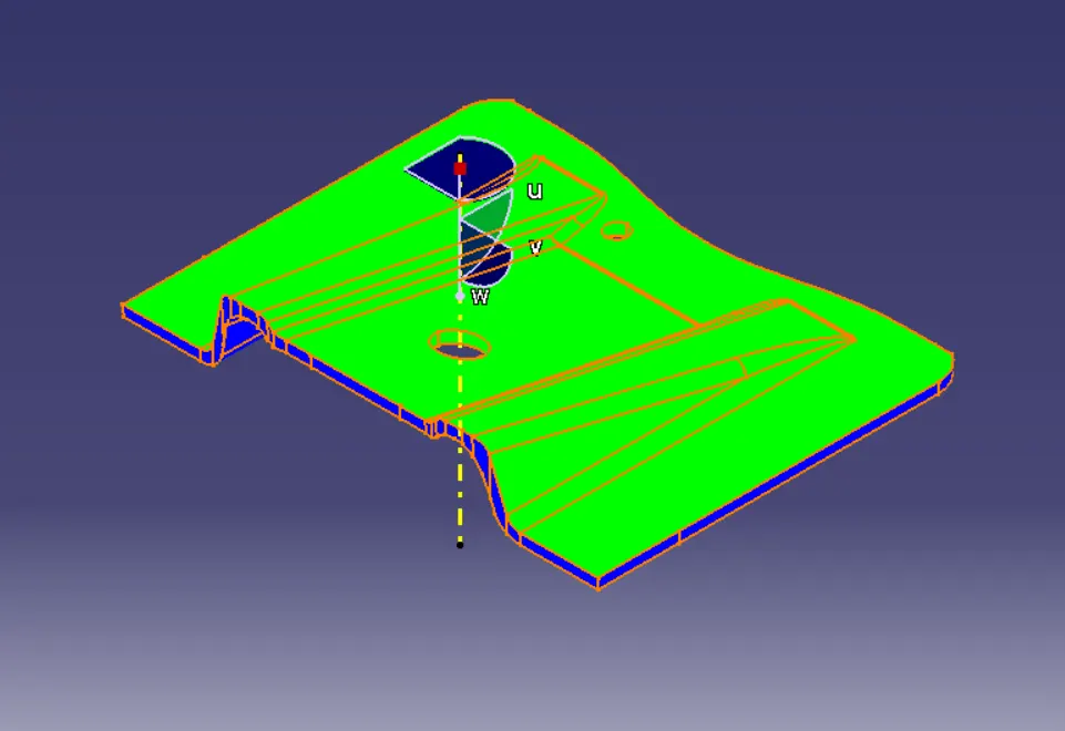
Following the Class A surface is given as the input for the component creation
Tooling Axis:
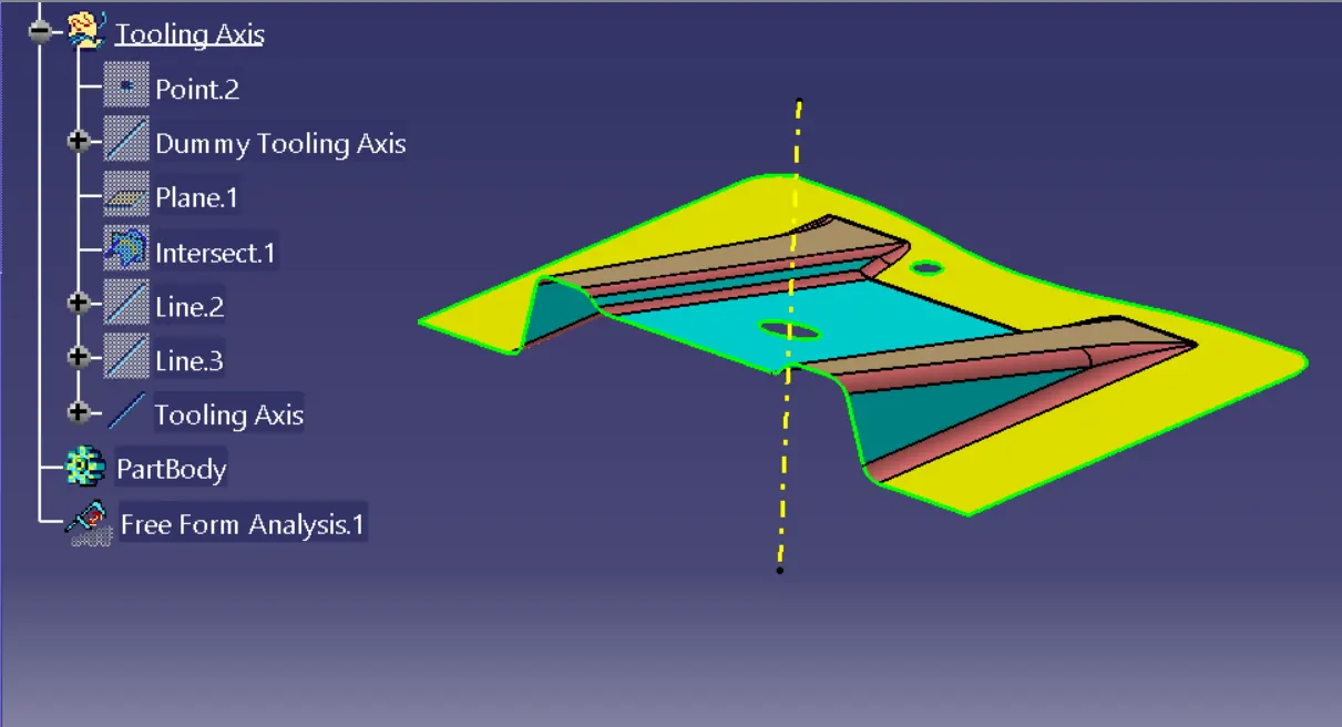
Tooling axis is the direction in which the mold or core and cavity opens. The ejection of the part from the mold depends on the draft. A zero draft can result in difficult or no ejection due to shrinkage. It is recommended to add a minimum of 0.5 to 1 degree, up to 3 degrees of draft for textured surfaces.
To create the tolling axis is by using the Bisecting Line
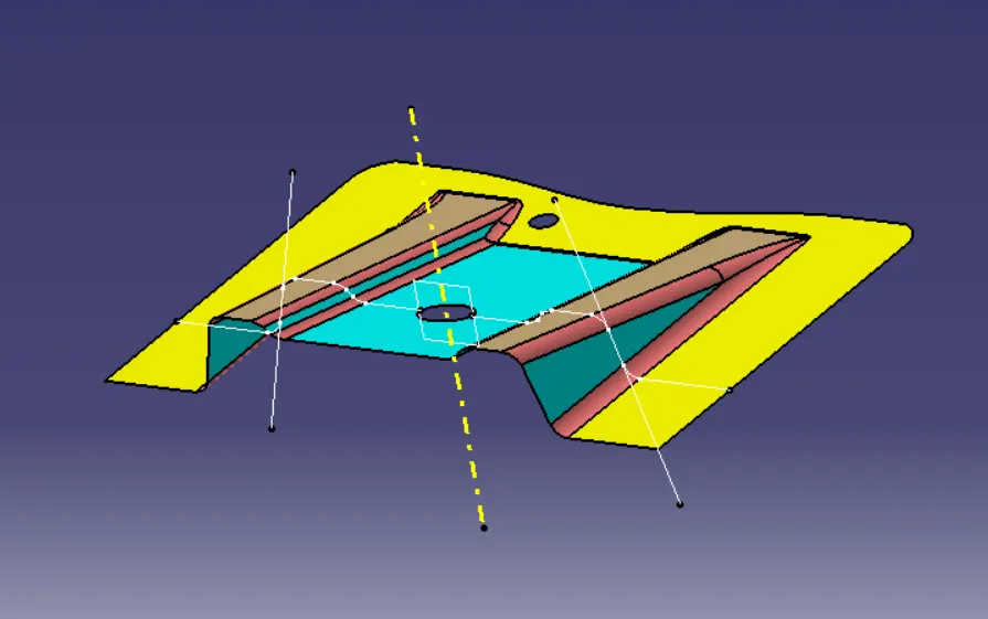
Draft :
Drafting provides angles or tapers on the product features such as walls, ribs, posts, and bosses that lie parallel to the direction of release from the mold, easing part ejection.
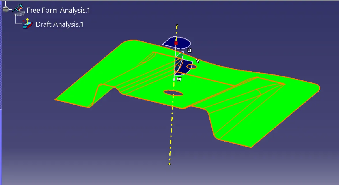
Draft Analysis:
It is a process that evaluates a part's geometry's angles and features relative to its mold's parting line.
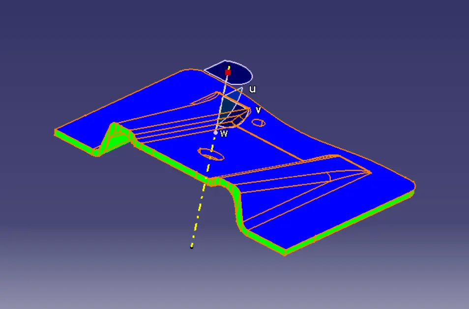
Draft Analysis Tool to Check the Draft,.
Using the Draft Analysis Tool, the Draft Analysis tool identifies the zones (using color codes) and highlights the areas which deviate from the specified values along a defined draft direction.
Class B Surface:
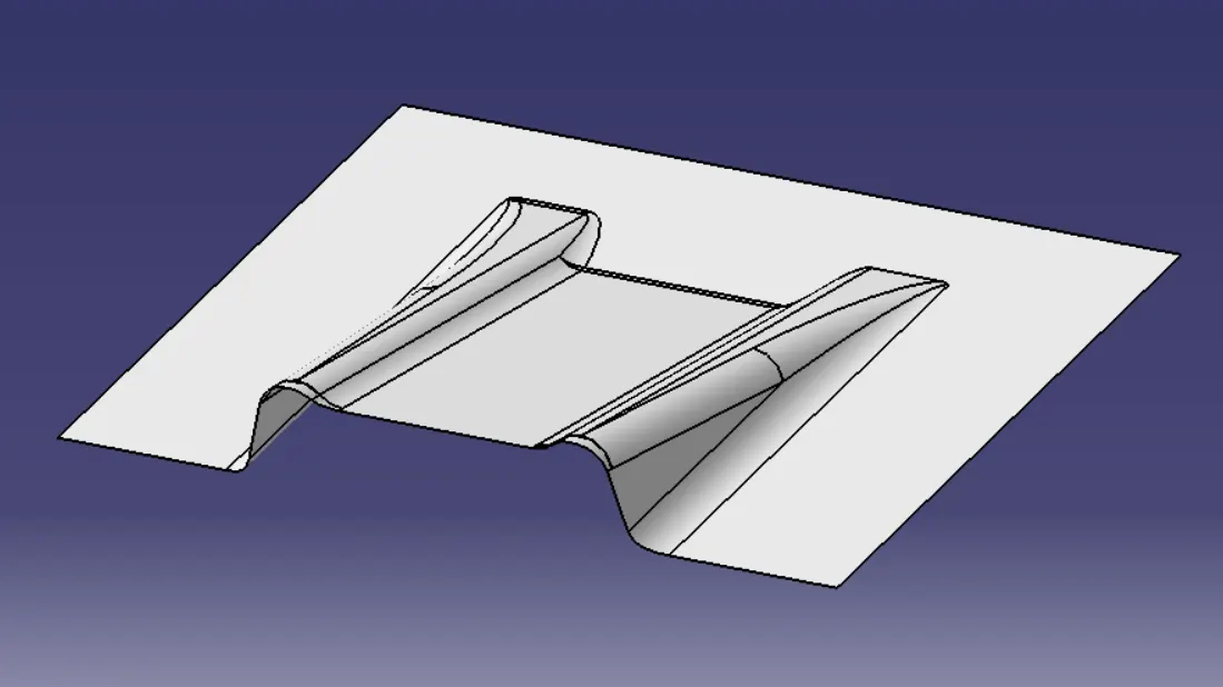
Class B refers to a secondary surface created by offsetting a primary Class A surface, primarily used for designing to functional aspects of a part, including adding thickness, ribs, and mounting points, which are not always visible on the final product.
- To create the Class B surface, we have extracted the surface from Class A and untrim, then to obtain the original parent surface.
- These surfaces are then offset to the required thickness(2.5mm).
- After offsetting, all the surfaces are trimmed into the required shapes.
- To give required fillets.
Class C Surface:
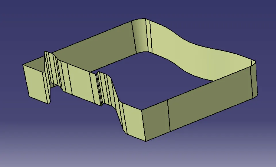
It connects Class A and Class B surfaces, typically created using sweep operations along defined direction to achieve a basic transition between the higher quality surfaces.
- To create the surface boundary on the Class A surface.
- Now the boundary curve is swept along the draft direction with a 3 degree draft.
- After Swept, to join the Class A and C surfaces.
- And finally trim into the Class B and C Surfaces.
- Joining the surface A and C.
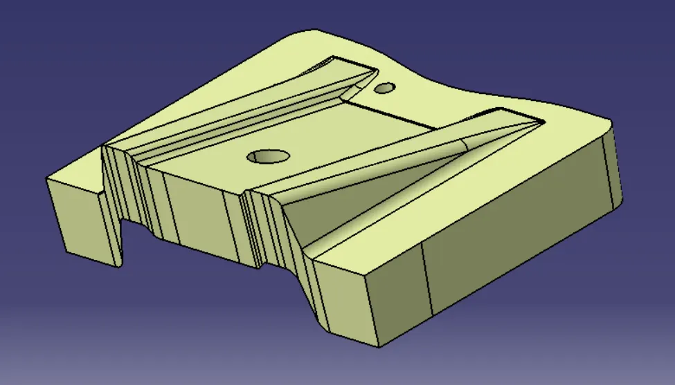
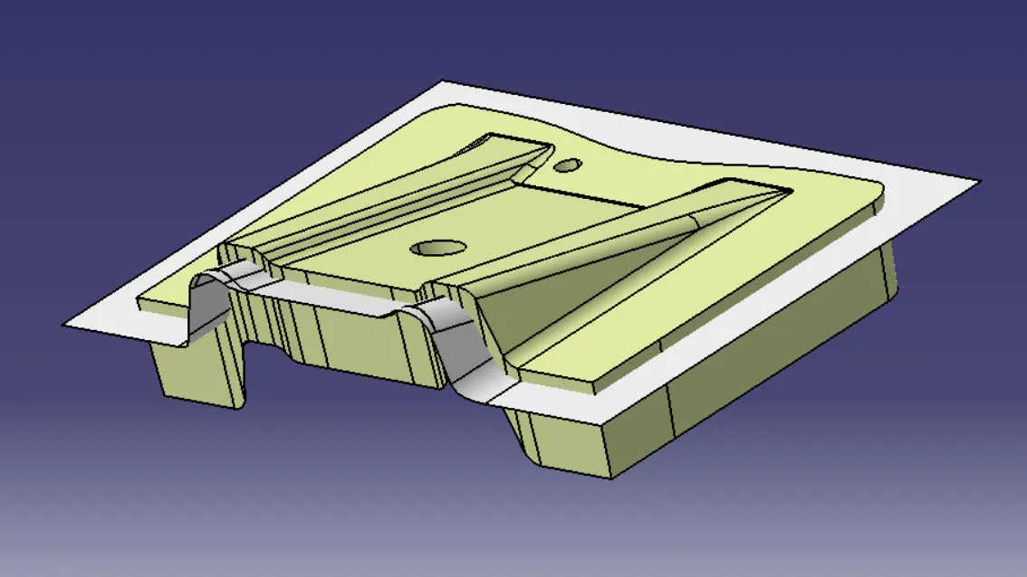
- Final Trimming
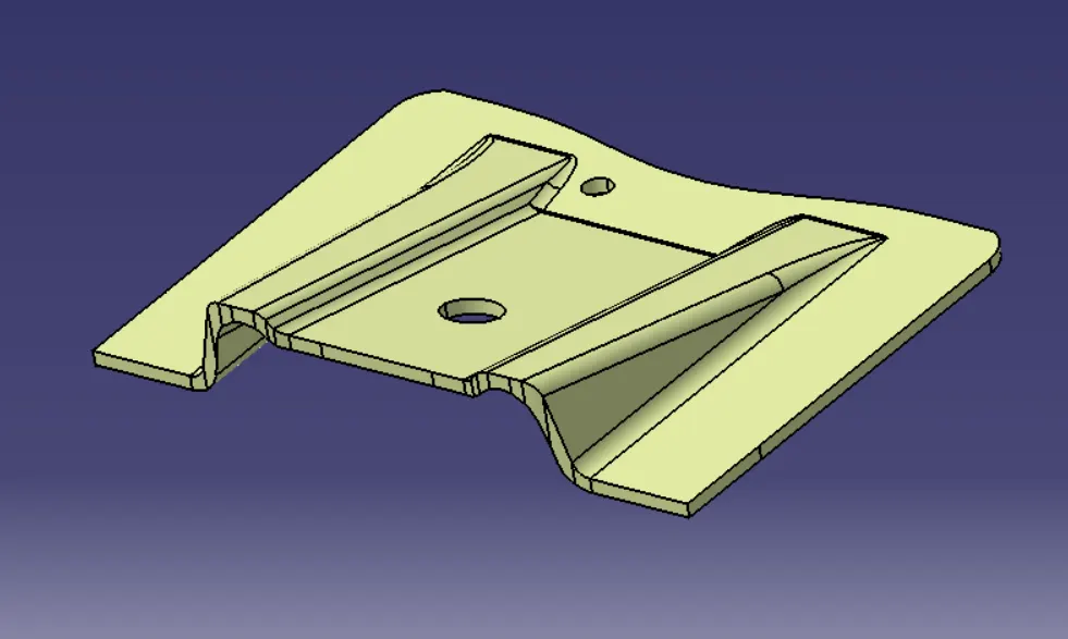
Close Body Surface:
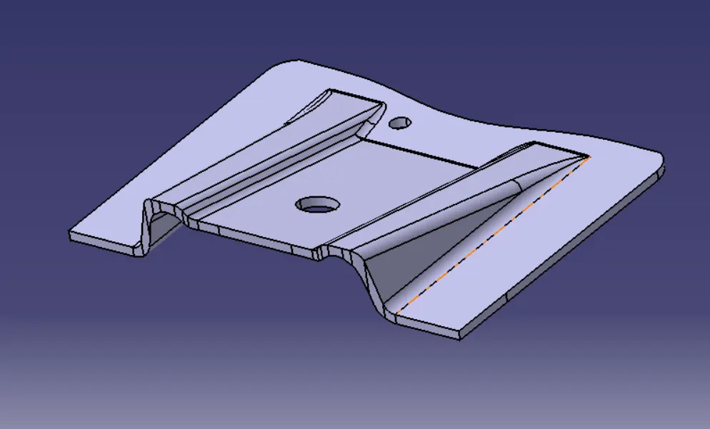
Draft Analysis: