Week 9 - Challenge 1 - Base Bracket Design
BASE BRACKET DESIGN
REPORT ABOUT DRAFT ANALYSIS USING TOOLING AXIS
Create Tooling Axis :-
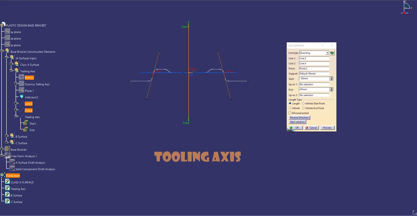
The direction at which the cavity or core moves throughout the manufacturing process is known as the tooling axis.
The tooling direction would initially be along the Z axis because of the hole, it was found after making sure the class A surface is gap-free. But we must apply the bisecting method in order to locate it.
Initially, a dummy tooling axis is made at the flat surface's hole center.
The class A surface is separated into various sections and labeled with different colors for easy identification.
Where the surface is more, intersect the class a surface along the YZ plane.
Extend the two lines on both sides because the Class A ribs are only one location that could be parallel to the dummy axis and fail the analysis.
The two expanded lines are joined to form a bisecting line.
The new line appears to be exactly parallel with the dummy line. It is therefore considered to be the tooling axis.
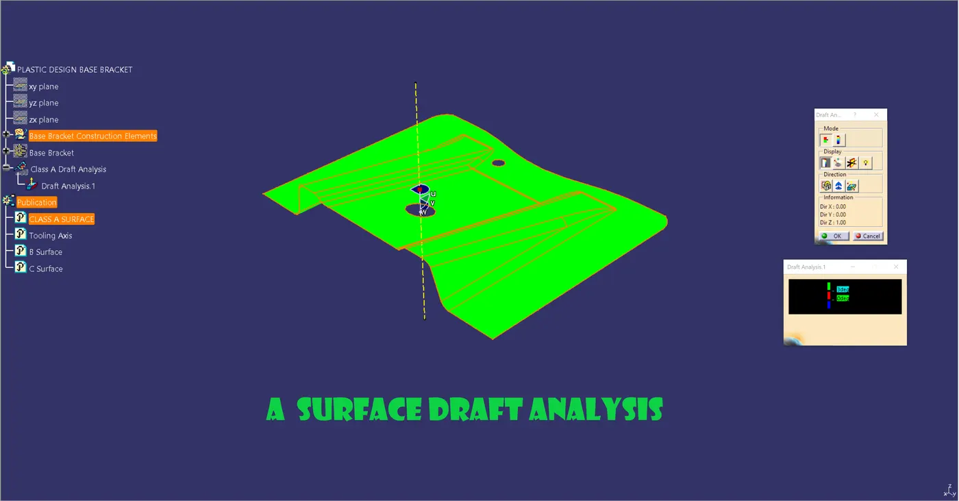
Draft Analysis For Class A Surface :-
Draft Analysis For Solid Part (Isometric, Front, Side, and Top View) :-
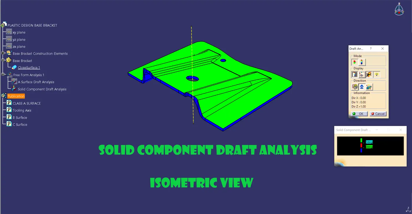
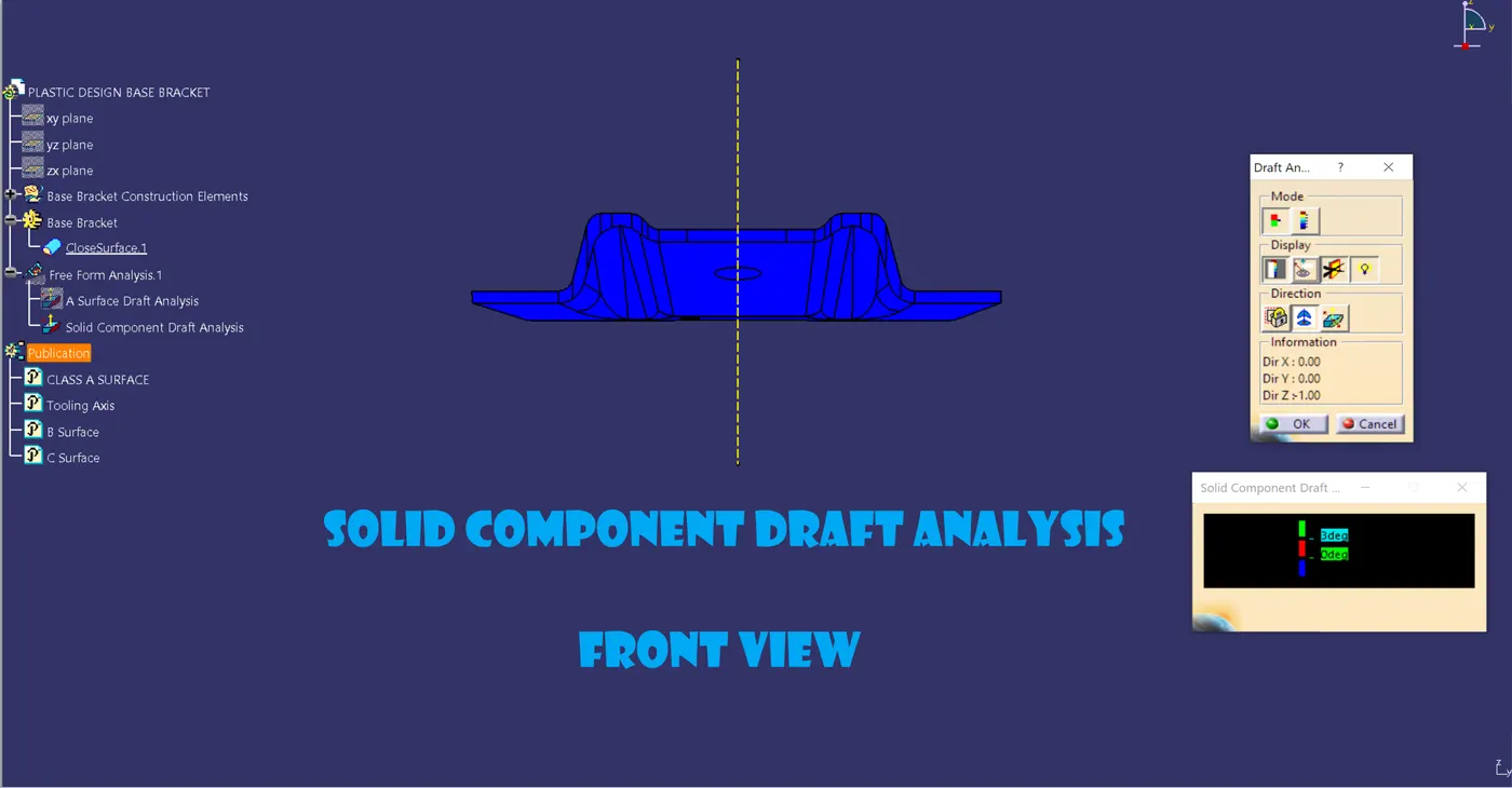
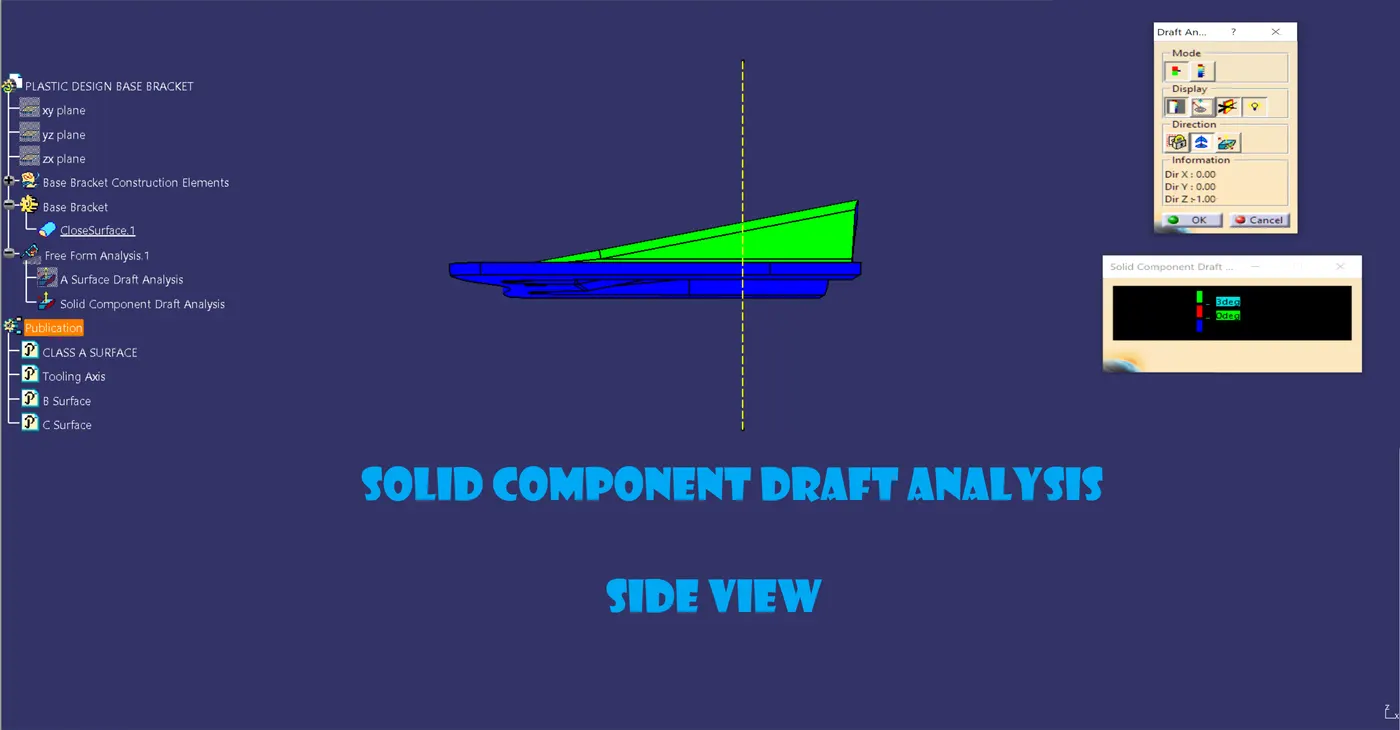
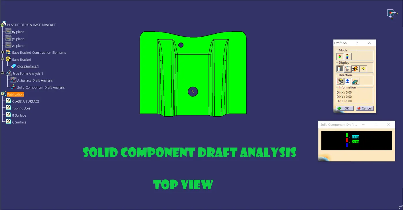
It is recommended to activate the'material' option from the material view icon before beginning the draft analysis.
Next, choose the draft analysis command and press the axis button.
Align yourself with the tooling direction by tapping the axis bar.
Verify if the section passes the draft analysis.
The surface that passes draft analysis with at least three degrees is indicated in green; below that, blue and red are displayed.