Week 9 - Challenge 1 - Base Bracket Design
Dear sir,
Here I have attached the detailed report of draft analysis for BASE Bracket Design.
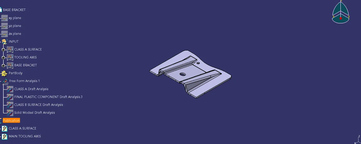
Screen shots of draft analysis of Class A Surface, Class B surface,Class C surface and Complete solid model.
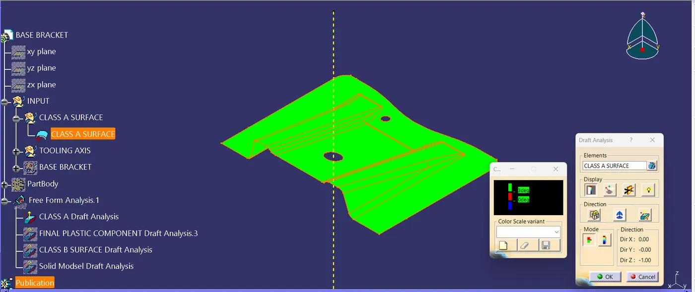
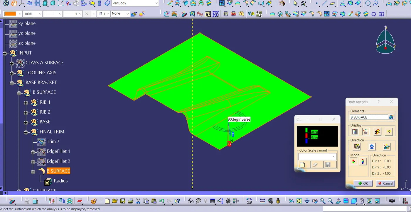
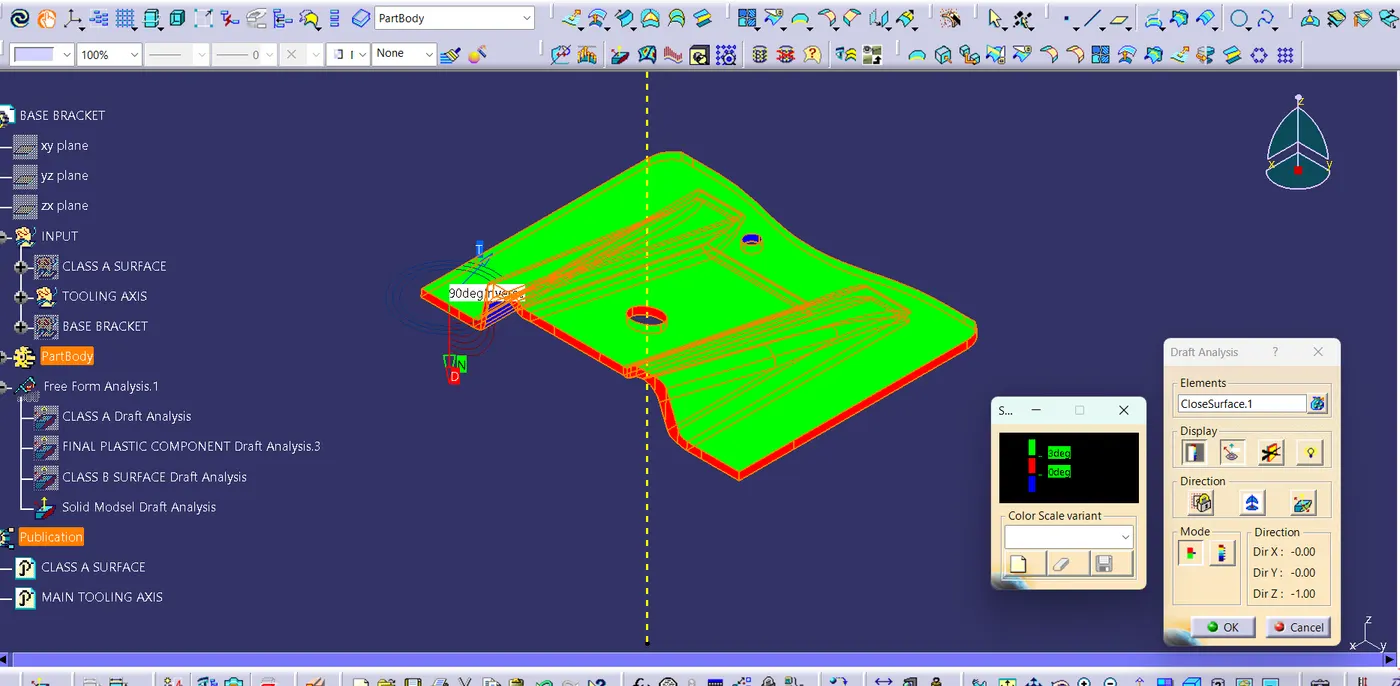
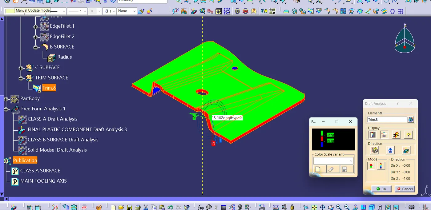
Screen shots of Various Orientations.
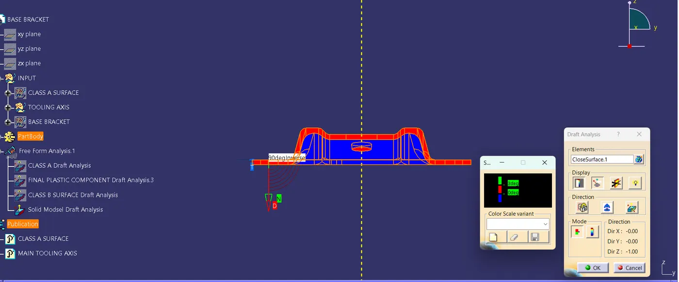
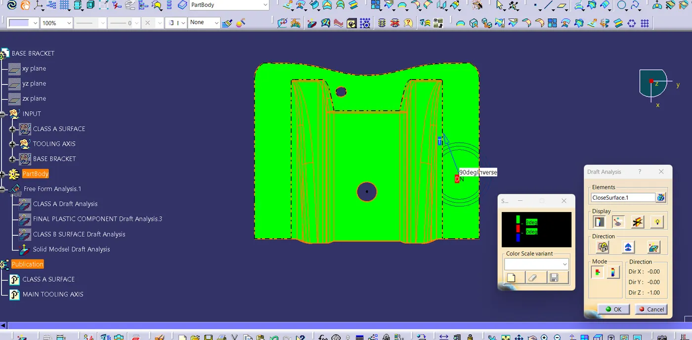
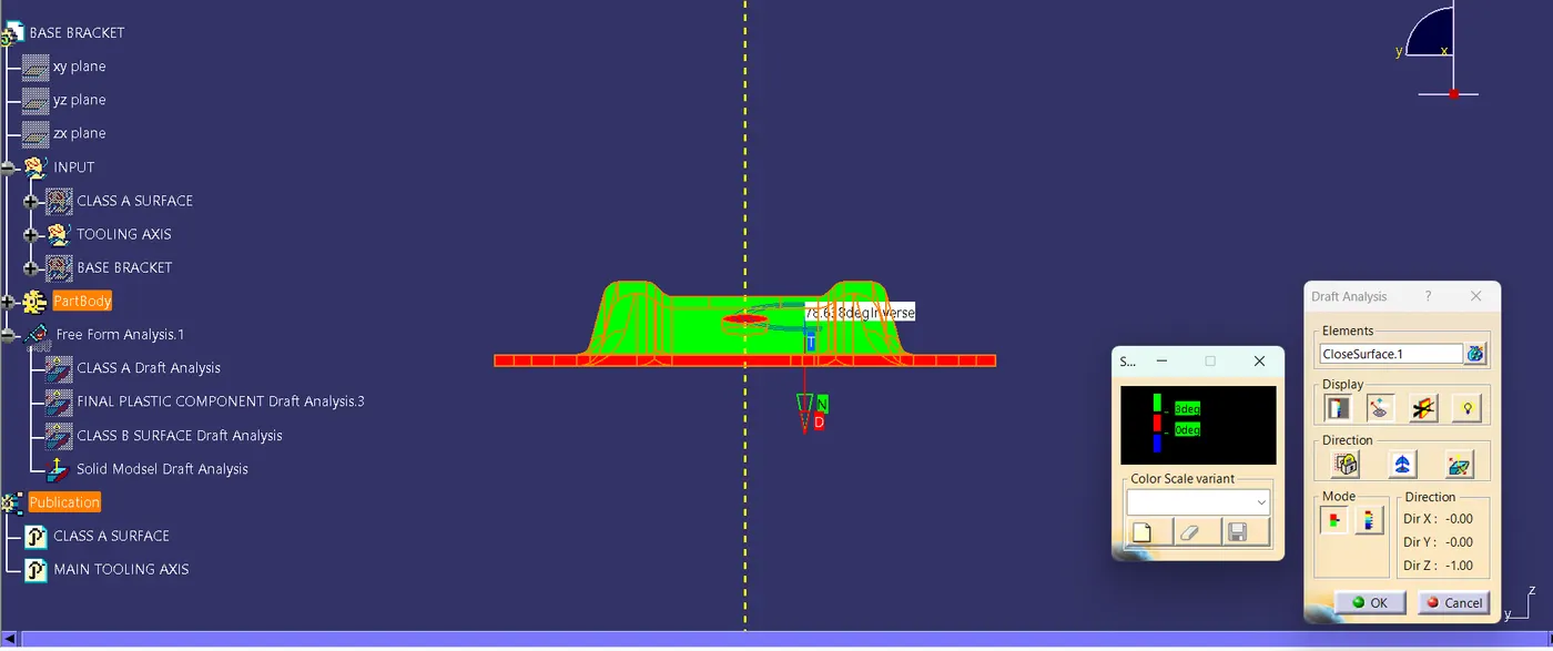
A draft angle is a taper applied to the vertical walls of the injection-molded component to assist with releasing the part from the mold. Draft angles are a required feature of injection-molded custom parts. A functional part for injection molding has to have draft angles that face both the cavity and core sides. This will reduce the risk of damage to the parts and ensure that they can be ejected from the machine.As the molten plastic flows into the closed die and fills the cavity, the material shrinks inside the mold upon cooling and as a result grips the core.
Screen Shots of Toolingh Axis:

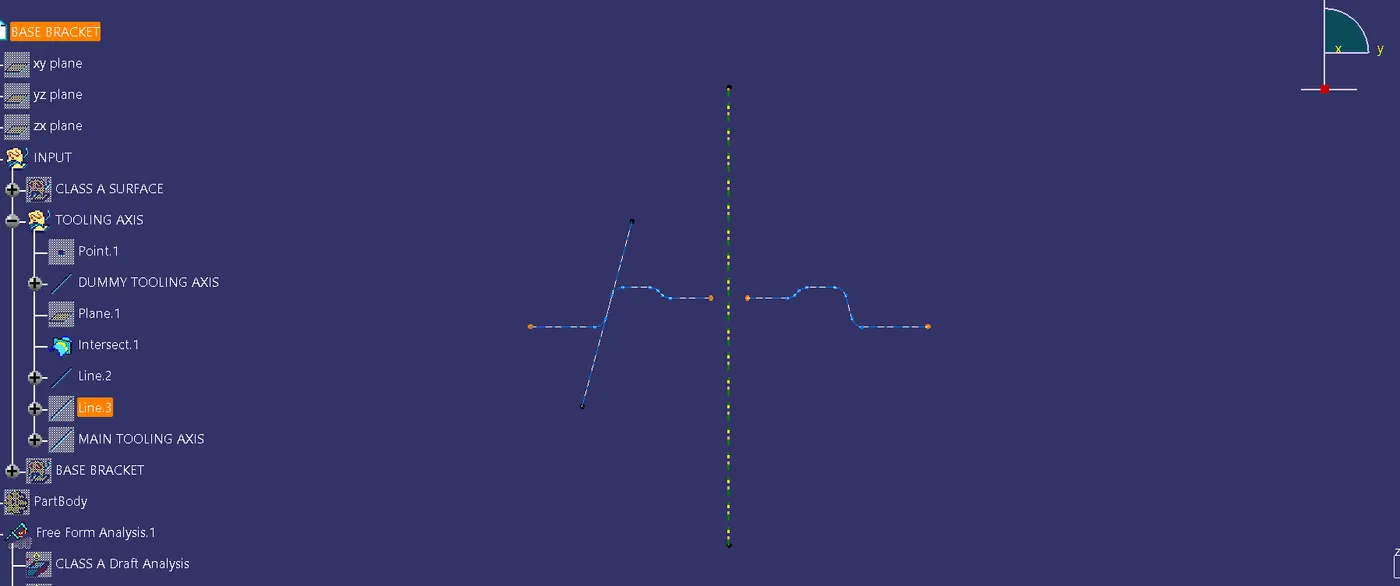
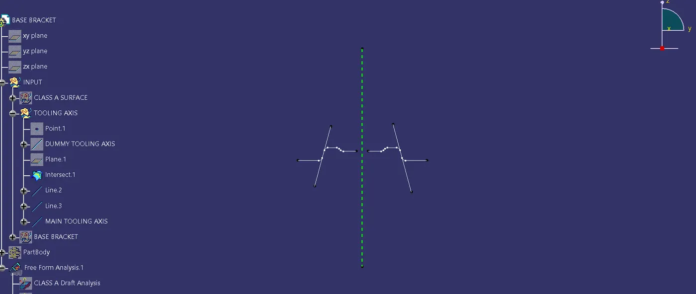
STEPS IN CREATING TOOLING AXIS:
STEP 1:Fisrt we create a point to define the Class A surfacde and Create dummy tooling axis at that point.
STEP 2: Create an Intersection points of Class A suraface with the help of refference plane.
STEP 3: Then create the parallel lines wherever the lines are seems parallel to dummy tooling axis.
STEP 4: Create the Bisecting line with respect to those two lines craeted on the insection points.
Thus the bisecting line is called as Main Tooling Axis.
Class A Surface:
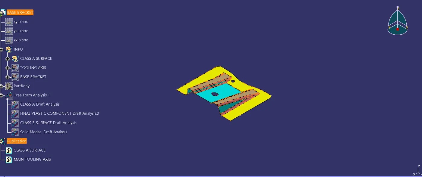
CLASS B Surface:
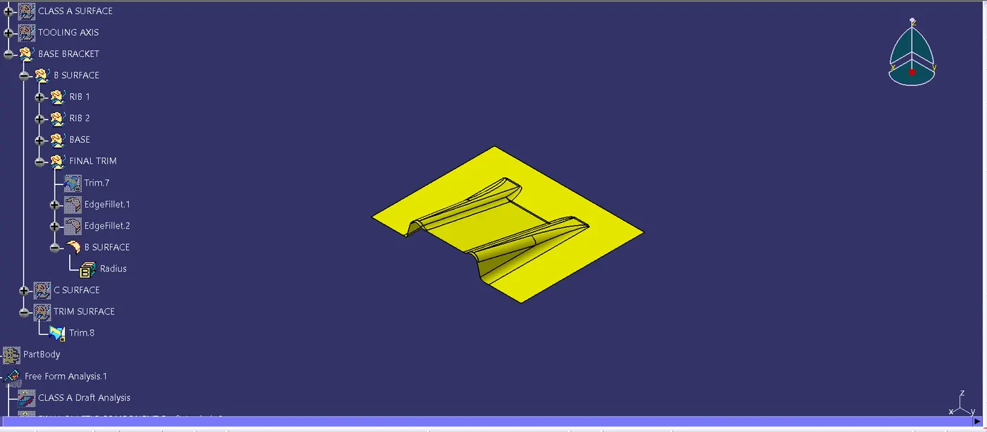
COMBINED PLASTIC SURFACE:

SOLID SURFACE
Thank you..